Welding seams of various lengths
TO
category:
Metal welding
Welding seams of various lengths
Next: Welding thin metal
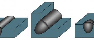
Weld seams are divided into three groups according to their length. The length of the welds is of great importance for choosing the order in which they are made.
Short seams are welded using the “pass” method, i.e., by continuous movement of the arc from one end of the seam to the other in one direction. In multilayer welding, each subsequent layer is applied in the direction opposite to the previous one.
Medium-length seams are welded from the middle of the seam to the edges, or in a reverse-step manner. This order of sutures reduces internal stresses and deformations. The deformations that occur when two adjacent short sutures are applied have the opposite direction.
The reverse-step welding method consists in dividing the entire seam into sections 200-300 mm long (steps). The length of the section is chosen such that welding can be carried out with a whole number of electrodes. When welding thin metal, the sections are made shorter, when welding thicker metal, the sections are made longer. Welding of each section (stage) is carried out in the direction opposite to the general direction of welding. The reverse-stage welding method has several varieties. Medium-length seams are welded in a reverse-step manner from one end of the seam to the other. Welding of each stage is carried out in the direction of the previous welded section in such a way that the end of each stage is welded to the beginning of the previous one.
Long-length seams are welded in a reverse-step manner from the middle to the edges. If welding is performed by one welder, then he applies the seams in the order shown in Fig. 1st century
Rice. 1. Welding seams of various lengths: a - from the middle to the edges of the seam; b - in a reverse stepwise manner from one end of the seam to the other; c, d - in a reverse stepwise manner from the middle to the edges of the seam; d - using a stepwise method from the middle to the edges of the seam, staggered
The method shown in Fig. 60 d, preferable, it is called this: a reverse-stage method of welding from the middle to the edges of the seam in a staggered manner. If welding is performed by two welders, then they apply seams in the order shown in Fig. 1 year
When welding multilayer seams using the reverse step method, the ends of sections (steps) in adjacent layers should not coincide, and they must be shifted by 15-20 mm. This is done because defects (lack of penetration, slag inclusions) are most likely to appear at the points of the beginning and end of the seams. Each subsequent layer should be done in the direction opposite to the previous one.
Reverse-stage welding method: essence and purpose
Produced by several welders simultaneously. It is used to reduce deformations when welding over long distances and to avoid warping of workpieces from overheating.
Stresses and deformations arise from uneven cooling or as a result of shrinkage of the weld pool during the cooling process. Shrinkage causes deformation in the metal adjacent to the bath.
In the automatic process - single-layer seams of any length, as well as in manual welding - short ones, up to 300 mm, the seams are welded from start to finish, the method is called pass-through. The reverse-step method, as a rule, involves dividing into sections from 100 to 300 mm.
Other criteria for classification of welded joints
In addition to the method of joining parts, seams differ in other parameters:
- According to the shape of the seam, convex and flat seams are distinguished,
- There are continuous and intermittent seams along the length,
- According to the position of the welded surfaces in space, there are horizontal, vertical, ceiling and bottom seams and other classifications.
Before starting work, it is important to determine the type of weld in all respects. This will help you choose the optimal welding technique in each specific case. For example, welding a fillet joint in a vertical position will require more preparation than welding a butt weld in a down position.
Classification of seams depending on length
Sections up to 300 mm are considered short.
Medium - from 300 to 1000 mm . The distance is divided into several zones, each one is welded in the direction opposite to the previous one. The length of the connections is chosen so that they require 2 to 3 whole electrodes.
Long - more than 1000 mm . Do it in a reverse stepwise manner from the middle to the edges. Connections of this length are used in shipbuilding and in the manufacture of large-volume tanks.
Welding seams of various lengths: a - from the middle to the edges of the seam; b - in a reverse stepwise manner from one end of the seam to the other; c, d - in a reverse stepwise manner from the middle to the edges of the seam; d - in a reverse stepwise manner from the middle to the edges of the seam, staggered
Technology for making seams of various lengths.
All welds, depending on their length, are divided into three groups: • short - up to 250 mm; • medium length - from 250 to 1000 mm; • long - from 1000 mm or more. Short seams are made “for passage” in one direction, that is, when the electrode moves from the beginning of the seam to the end (Fig. 21, a). When making seams of medium and long lengths, warping of products is possible. To avoid this, medium-length seams are made “pass through” from the middle to the ends (Fig. 21, b) or in a reverse-step manner (Fig. 21, c), the essence of which is that the entire seam is divided into sections 100-350 long mm in such a way that each of them can be made with an integer number of electrodes (two, three, etc.). In this case, the transition from section to section is combined with a change of electrode. Each section is welded in the direction opposite to the general direction of welding, and the last one is always welded “out”. Long seams are made from the middle to the ends in a reverse-step manner (Fig. 21, d). In this case, it is possible to organize the work of two welders simultaneously.
Rice. 21. Making seams of various lengths: 1-7 - sequence of sutures
Ticket number 22
Gas welding of pipe structures.
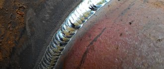
Gas welding of small-diameter pipes (up to 100 mm with a wall thickness of up to 2-3 mm) is widely used, especially during the installation of heating and hot water supply systems, water pipelines, gas pipelines and other tubular structures. Pipes are most often butt welded, since butt joints require the simplest preparation of edges, the least amount of time and consumption of flammable gas. When the pipe wall thickness is up to 5 mm, welding is carried out without cutting the edges, and the joint is assembled with a gap of 1.5-2 mm. When welding pipes with a wall thickness of more than 5 mm, one-sided cutting of the edges is used at an angle of 70-90º, leaving a bluntness of 1.5 to 2.5 mm. Blunting is necessary so that during welding the edges do not melt through and the molten metal does not flow into the pipe. Depending on the purpose of the structure, other methods of joining pipes are used - without beveled edges with a backing ring, with a socket and an insert ring. Before welding, the pipes are aligned so that their axes coincide and are clamped. Centralizers and other devices are used to center pipes. Pipe welding can be done using both left and right methods. Using gas welding, the joints are welded in one layer. If the pipe can be rotated, then welding is carried out in the lower position; a fixed joint is welded in all spatial positions, which is the most difficult for the welder. Welding of large diameter pipes (300 mm or more) is carried out in four separate sections, as shown in Fig. 56, a.
Rice. 56. Sequence of welding large diameter pipes: a - 200-300 mm; b - 500-600 mm; c - welding without rotation
When welding pipes with a diameter of 500-600 mm, welding can be carried out simultaneously by two welders. First, the upper part of the pipe is welded in sections 1 and 2 (Fig. 56, b), then the pipe is turned and sections 3 and 4 are also welded simultaneously. If the pipe cannot be rotated, then sections 3 and 4 are welded in the order shown in Fig. 56, in, dotted arrows.
Ticket number 23
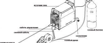
1. Question Welding torches (purpose, classification, design, marking, preparation for work, safety requirements). The welding torch is used to mix flammable gas or flammable liquid vapor with oxygen and produce a welding flame. Welding torches are divided as follows: • according to the method of supplying combustible gas and oxygen to the mixing chamber - injection and non-injector; • by the type of combustible gas used - acetylene, for substitute gases, for liquid combustibles and hydrogen; • by purpose - universal (welding, cutting, soldering, surfacing) and specialized (performing one operation). An injection burner (Fig. 15) is a burner in which the supply of combustible gas to the mixing chamber is carried out due to its suction by a stream of oxygen flowing at high speed from the nozzle opening. This process of sucking gas of lower pressure with a stream of oxygen supplied at a higher pressure is called injection, and burners of this type are called injection burners.
Rice. 15. Design of an injection welding torch: 1 - mouthpiece; 2 — replaceable tip; 3 - mixing chamber; 4 — injector nozzle; 5 - oxygen valve; 6 — oxygen nipple; 7 - acetylene valve; 8 - acetylene nipple
For normal operation of injection burners, it is necessary that the oxygen pressure be 0.15-0.5 MPa, and the acetylene pressure is much lower - 0.001-0.12 MPa. Its operating principle is as follows. Oxygen from the cylinder under operating pressure through the nipple, tube and valve 5 enters the injector nozzle 4. Coming out of the injector nozzle at high speed, oxygen creates a vacuum in the acetylene channel, as a result of which acetylene, passing through nipple 6, tube and valve 7, is sucked in into mixing chamber 3. In this chamber, oxygen, mixing with flammable gas, forms a flammable mixture. The flammable mixture, exiting through the mouthpiece 1, is ignited and, burning, forms a welding flame. The supply of gases to the burner is regulated by oxygen valve 5 and acetylene valve 7, located on the burner body. Replaceable tips 2 are connected to the burner body with a union nut. A non-injector burner is a burner in which combustible gas and heating oxygen are supplied at approximately the same pressure of 0.05-0.1 MPa. They do not have an injector, which is replaced by a simple mixing nozzle that is screwed into the burner tip tube. Rules for handling burners:
1. Operation of faulty burners is not allowed, as this can lead to explosions and fires, as well as burns to the gas welder. 2. A working torch produces a normal and stable welding flame. 3. To check the burner injector, connect the hose from the oxygen reducer to the oxygen nipple, and the tip to the burner body. The tip is tightened with a wrench, the acetylene valve is opened and the required oxygen pressure is set using the oxygen reducer according to the tip number.
Let oxygen into the burner by opening the oxygen valve. Oxygen passing through the injector creates a vacuum in the acetylene channels and acetylene nipple, which can be detected by placing a finger on the acetylene nipple. If there is a vacuum, the finger will stick to the nipple. If there is no vacuum, it is necessary to close the oxygen valve, unscrew the tip, unscrew the injector and check whether its hole is clogged. If it becomes clogged, it must be cleaned, and the holes in the mixing chamber and mouthpiece must also be checked. After making sure that they are in good working order, repeat the suction (vacuum) test. 4. The amount of suction depends on the gap between the end of the injector and the entrance to the mixing chamber. If the gap is small, then the vacuum in the acetylene channels will be insufficient; in this case, the injector should be slightly unscrewed from the mixing chamber. 5. First, open the oxygen valve of the burner slightly, thereby creating a vacuum in the acetylene channels. Then open the acetylene valve and ignite the combustible mixture. 6. The flame is regulated with an acetylene valve with the oxygen valve fully open. 7. When there is a pop, first close the acetylene and then the oxygen valves. 8. Causes of popping noises: • severe overheating of the burner; • clogging of the burner mouthpiece; • if the flow rate of the combustible mixture becomes less than the speed of its combustion, the flame will penetrate into the mouthpiece channel and a back blow will occur. 9. In this case, the burner must be extinguished, cooled with water and the mouthpiece cleaned with a needle.
Ticket No. 24
Methods for making welding seams of various lengths
The size of each grip is determined so that a whole number of electrodes are removed. This is done so that the weld pool is heated evenly. If the metal is thin, the seams are shorter, if the metal is thick, the seams are longer. Types of reverse-stage welding:
- In sections - welding is carried out in parallel and simultaneously by two welders.
- In a cascade - in steps, layer by layer: after the first, the surface is cleaned and prepared, the second is made longer than the first. Step back 30-40 mm and apply a third layer.
- Slide - cascades of seams lead towards each other, forming a slide.
To avoid deformation, electrodes of larger diameter and higher current are used. Vertical lap and circular T-seams are made on both sides using a reverse-step method.
Workpieces with a thickness greater than average are connected with multi-layer seams. In this case, the first one is continuous, the subsequent ones are reverse-staged, in sections. The ends of sections in adjacent layers should not coincide; they are shifted by 15-20 mm due to the fact that slag inclusions and lack of penetration are likely at the end points.
Electric arc in manual arc welding
Excitation of the welding arc
Excitation of the arc can occur in two ways. You can touch the metal being welded with the electrode, and then withdraw the electrode to a distance of 3-4 mm, maintaining the burning of the resulting arc.
You can light an arc by touching the metal being welded with a quick lateral movement and then withdrawing the electrode to a distance of 3-4 mm (this movement is similar to how a match is lit). The contact of the electrode with the metal must be short-term, otherwise the electrode will be welded to the metal. The welded electrode should be torn off by turning it to the sides with sharp movements.
Arc length
In the process of welding metal, it is necessary to maintain a welding arc of a certain length, depending on the brand of the electrode and its diameter. The length of the arc largely determines the quality of welding and the shape of the weld.
The recommended welding arc length is 0.5-1.1 times the electrode diameter. If the arc is short, this can cause welding of the electrode to the metal, interruption of the arc and disruption of the welding process.
With a large arc length, its combustion becomes unstable, the penetration depth decreases, the molten electrode metal splashes and the weld metal is saturated with nitrogen and oxygen. In this case, it is difficult to obtain a weld with the required shape. For electrodes with a thick coating, the manufacturer indicates the recommended arc length in the data sheet. The ability to maintain a constant arc length throughout the entire welding process determines the professional level of the welder.
SUTURES FOR METAL THICKNESS MORE THAN 15 MM
WITH THE CASCADE METHOD, the seam is divided into sections of 200 mm. After welding the first layer of the first section, without stopping, continue to lay the first layer on the adjacent section. Then each subsequent layer is applied to the metal of the previous layer that has not had time to cool
WELDING “HILL” is a type of cascade method. Conducted by two welders simultaneously from the middle to the edges
Both methods are reverse-stage welding not only along the length, but also along the cross-section of the seam, and the welding zone always remains hot
WHEN WELDING WITH BLOCKS, the seam is filled in separate steps along the entire height of the seam section. Used when connecting parts made of steels that are hardened during welding
Source
Electrode movement technique for manual arc welding
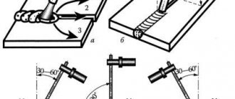
When welding, the electrode must move in three directions, shown in the figure on the left.
The first movement (direction a) is a translational movement along the axis of the electrode (item 1) into the welding zone. To maintain a stable arc, the speed of this movement is equal to the melting speed of the electrode.
The second movement (direction b) is the forward movement of the electrode along the weld line (item 2). The speed of this movement depends on the strength of the welding current, the diameter of the electrode and other factors.
If the speed is too high, there is a risk of lack of penetration. Such defects in the weld are formed due to the fact that at a high speed of movement of the electrode, the deposited metal does not have time to fuse with the base metal. At a low speed of movement of the electrode, overheating and burning through the metal being welded is possible (especially when welding thin metal) and welding productivity decreases. In the absence of transverse movements of the electrode, the weld is obtained with a width of about 1.5 times the diameter of the electrode. Thin sheet metal is welded using similar seams, and the root of a multilayer weld is also welded.
The third movement of the electrode is the transverse oscillatory movement of the electrode (arrow c). They are used to obtain the required seam width and penetration depth. Transverse movements slow down the cooling process of the resulting weld, promote the removal of gases and slags and ensure good fusion of the base and deposited metal, significantly improving the quality of welding. The crater formed at the end of the bead surfacing is carefully welded.
Electrode position for manual arc welding
The position of the electrode during the welding process depends on the spatial location of the seam, the thickness and grade of the metal being welded, the diameter of the electrode itself, and the thickness and grade of its coating.
Welding can be done from right to left, left to right, away from you, towards you. In this case, in any direction of welding, the angle of inclination of the electrode should ensure penetration of the metal to a small depth and the correct formation of the weld. The figure on the right shows the recommended position of the electrode when welding in different directions: