Switches and load switches (SBs) are manually operated switching devices that switch on or off a circuit that is under load or has been previously de-energized. Since the function of the load switch is simple (opening the electrical circuit), it does not respond to short circuit currents or overload currents, which is why it differs from a circuit breaker (AB).
The main components of the switch are the power contacts and the spring drive necessary to speed up the release of the contacts. When opening and closing contacts, as is known, a spark or discharge occurs. Physically, this process is simple: an electric arc occurs at the contacts while the voltage is maintained. The power and size of the discharge depends only on the current indicators. Therefore, the switch is, first of all, designed to close (open) a network with high currents and extinguish the electric arc that occurs at the same time.
BUY SWITCH SWITCHES
What is a switch
Electric switch
Products of various designs can be found in the entrances and basements of houses, on the street and in public buildings. In most cases, all types of switches are located in switchboards completely or partially.
According to the classification, an electric switch is part of a distribution mechanism and is designed to open the circuit manually. The product is designed to operate in the range of 100-1000 amperes at a maximum voltage of 1000 volts. The current is interrupted by muscular effort by creating a break in the line.
The changeover switch can be manufactured in open and closed versions. The design depends on the magnitude of the load that is applied to the contacts. This is justified by the fact that the rotary switch at the stage of activation and deactivation creates an arc and a sheaf of sparks, which can cause injury to a person and cause a fire.
The products operate on direct and alternating voltage and can be used for switching single-phase and three-phase current.
380 V switches are used in production and in homes where consumers operating from this voltage are installed. In private homes and cottages, it is common practice to use 220 V two-phase switching devices.
CS-CS.Net: Laboratory of the Electroshaman
Switches (disconnectors) ABB E200 and OT series
And again I delight you with fresh posts after some lull. The lull was caused by the fact that I was actively burning: coming up with new ideas, kicking orders, working in the fields (assembling shields and connecting some of the old orders together with my Partner).
Attention! Since the fall of 2015, the E200 series of circuit breakers has finally been discontinued! Instead, there are already new switches of the SD200 series. Read the post about them and DO NOT use the E200 series. And if you see a project that still says E20x - KILL the designer, don’t pay him money, because he DOES NOT know anything at all and does not know how to make projects!
This post has been brewing for a long time, and perfectly coincided with several questions that fell on me in a row: “Why are you insistently declaring here that a switch is needed! Yes, I’ll put a machine gun in his place and okay, why are you arguing?” and questions like “Why is a switch better than a machine and where should I put what?” To answer them, I’m writing this post because the housing of one of the switches very successfully broke, and I decided to take it apart and take a photo. And to make it more interesting, I bought a cheap switch of a different series (OT25) and also broke it and took a photo. Let's go read!
So, first the theoretical part. A switch (or power disconnector) is a regular switch, but powerful. The task of the switch is simply to turn off the power to some line. That's what they are used for. Actually, the explanation could end there. But no =) We will apply it to our shields and our work, and describe it in more detail =)
So, here's where the switch can be useful. Firstly, on the input. Because the PUE literally says that there must be some kind of switching device in front of the meter that can be used to de-energize the meter in order to replace/verify it. In some cases, the role of the switch can be played by an introductory machine, and in some cases it will be more convenient to install the switch first, and then, after the meter, the machine.
Secondly, the switch is technically simpler: there is nothing there except contacts. This means that it is more reliable than a machine, which also has all sorts of current releases. And similarly, at critical places on the input cable coming from the substation/input, it is best to first install a switch: turn it off and change what you want and how you want.
Thirdly, in some cases, for example, when using non-switchable lines, we need a switch to turn off the power to the panel. Another good practice is to start the panel with a switch: there will be somewhere to run the power cable.
I am often asked whether it is necessary to break the zero with a switch at the input to the switchboard . Many are afraid that this is a zero - what if it turns on later than the phases or does not turn on at all, and the switch will cause a “zero burnout” inside the shield.
I always break the zero at the input in the switchboard with a switch and here's why. Firstly, in domestic construction (houses, cottages) we are often forced to use the “TT” grounding system (I remind you of the post about bushings), in which, in the event of various accidents, anything can fly to the neutral wire - even a phase. If the switch breaks zero, then it will completely protect you from such accidents. Secondly, if we talk about the assembly of switchboards, then the zero on the switch gives us a convenient point for connecting the input cable, intuitively understandable: Ground (PE) - to the busbar, and everything else - to one place on the switchboard, to the main input switch.
to NOT break the zero with a switch in one case: if you are making a control panel/ASU for a TN-CS grounding system, in which the input zero is considered a PEN conductor, and this PEN conductor must under no circumstances be disconnected, but must be immediately connected to grounding bus.
If you are concerned that the zero of the switch may fall off or turn on later, then special additional poles are produced especially for you in OT switches, which are turned on first and turned off last. I install the usual zero poles OTPS80FP (for OT switches of 63 and 80A) or OTPS125FP (for OT switches of 100 and 125A), and over all the years of assembling panels, only one pole turned out to be defective - it simply did not turn on.
In modular switches SD200 (and old E200), the delay between turning on zero and phases is small, and the equipment does not have time to notice it. And for those who are completely paranoid, I remind you that now all switchboards have a voltage relay at the input. So if there are problems with the zero in the input switch, then these relays will save us.
Some Kulibins use a high-denomination machine as a switch. Let's say, with an introductory voltage of 25A, they set the machine to 63 and rejoice. And some duplicate the input machine in the floor panel and in the apartment panel. This is all you don’t need to do! There should be ONE input machine - where it belongs. If it is located in the floor panel, put a switch in the apartment!
Well, now let's move on from vague words to action. So, ABB has two series of switches left. These are E200 and OT . The latest series is replacing E200 , and it is best to use it. Let me describe the brief features of these series.
E200 series are simple modular switches in automatic format. The handle can be of two colors: red and gray. There are from one to 4 poles. They look rather flimsy and are now made in Bulgaria. They can't do anything other than turn it on and off. Their advantage is the minimum space they occupy in panels ( OT with less than 3 poles in principle do not exist) and the ease of switching: even the weakest fingers can handle it.
They are designated simply and bluntly: E20<number of poles><handle color: r - red; g - gray>. That is, E202r 63 means a two-pole switch with a red handle for a current of up to 63 amperes. By the way, this is my warehouse item - a popular product that I put in my shields.
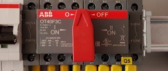
OT series switches have a much wider range of capabilities and do not have an easily described standard designation. But they have an infernal mechanism that snaps them sharply, preventing the formation of an arc between the contacts at the moment of switching on and off. They have a bunch of accessories in the form of additional poles (you can, for example, create a five-pole switch from a regular three-pole one), types of handles (for a switch, for a switchboard, for a cabinet) and are even immediately available in a waterproof case so that, for example, you can put it on the wall of a house . They can also be reversible (with positions I-0-II), and they can be used to switch power from the Network to the Generator, organize a bypass for the stabilizer/UPS and other similar things.
This is their downside (for us). Firstly, only a person with strong fingers can switch it. Some sweet and gentle woman - no. And they also come with at least three poles, eating up the extra modules of the single-phase shield.
This is how I make my choice of episodes. If the shield is single-phase, budget, or for small currents (up to 40A), then I install E202r 63. If the shield will be used with a higher rating of the input circuit breaker (40-50-63A) or three-phase, then I install an OT63F3 (three-pole for 63A ). And if there is a need to break 4 poles, I order 4-pole switches. And reversible ones too if necessary.
I always take the current from the switches to 63A. This is the most popular position of all warehouses, and it also allows, in case of a shortage of materials, to quickly take switches from stock. Let’s say, if I’m assembling two panels, and both have switches for 63A (despite the fact that one panel is for the input circuit breaker at 25A, and the other is for 40A), then if only one arrived, I urgently need to assemble another panel (holding the first ) - you can do this easily, because the position is the same.
Here are some switches lying around my house:
Types of terminals for E200 and OT series disconnectors
The leftmost one, as you understand, is E202r 63 , then OT25E3 , and then OT63F3 . 63rd is for ordering, so we won’t disassemble it. But we’re dissecting the first two, because it’s interesting to find out what’s inside. In principle, when you take the switches in your hands, you can immediately see that the OT series is harsh. It seems that it was designed by harsh Chelyabinsk residents. And it is better thought out, of course. To the point that all the designations and operational data are written on the switch, and on the box there is a drawing of holes for attaching the switch to the mounting panel (we cut out cardboard from the box with scissors, attached it, and marked the holes).
Marking of switch ABB OT63F3
We start with a simple patient. There were rumors on the MasterCity forums that these switches break the pole in two places, and as such they do not have a moving contact.
Here, perhaps, it is necessary to say a few words about moving and stationary contact. Historically, the switch, as I tried to write above, was used to create a line break visible to the eye. That is, the stern man turned the handle, the contacts moved away, and he saw it with his eyes. Usually the switch was made like this: some contacts were stationary, while others moved and came into contact with them.
And then people thought of it with their heads and decided to make switches like this. They placed a fixed contact on top, and a movable one on the bottom. And they supplied the incoming power to a fixed contact. The essence of all these manipulations is safety: if something breaks in the mechanics, then the fixed contact, which is under voltage, will remain as it was with a greater probability than the moving one. And let the moving one fall anywhere =)
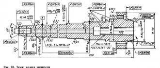
Actually, if you look carefully at the diagram drawn on a machine, switch or something else, then usually the upper contacts are fixed, and the lower ones are movable (header photo). This is where the legs of the rule “incoming food always comes from above” grow.
So, take a drill and boldly drill out all the rivets:
We prepare the switch E202r 63: we drill out the rivets
...and we discover that these switches are made up of single modules with rivets. And since the body of this switch was cracked at only one of the poles, now I have a single-pole 63 ampere switch. Someone like a neighbor needs to put it in a shield 
A two-pole switch consists of two separate
Open the case and LAM! The design is HARD =) But the most interesting thing is the complete discrepancy with the diagram! In the photo above you can see that the switch is turned off. Lever down. It is shown that the upper contacts are stationary. Now look at the photo below. There's a lever at the bottom too. That is, the right contact in the photo is the top one. And what? It's the other way around! He's mobile. Gee gee gee gee gee =))
Internals of the E200 switch: moving and fixed contact
Here you can take a closer look at the entire mechanism when it is turned on:
Internals of the switch (switch on)
In general, I laughed a lot at these switches. I was skeptical about them before, but now it’s even more fun. But on the other hand, not everything is so bad as to cause panic: “Oh, the E200 is crap, and change them all urgently.” As I wrote above, I use them in switchboards (and will use them) if the shield is used by personnel with weak fingers, and if in the shield you have to fight for each module, and the input allows you to install such a switch with a current reserve.
But the OT series was more fun. If with the E200 it was dangerous not to break the switch itself with an awkward movement, then when disassembling the OT series it was dangerous not to break your fingers or get hit in the eye by a spring. Now you will find out why. At a minimum, because these switches are produced by hot Finnish guys, apparently on the advice of tough Chelyabinsk men. Because there was no way to disassemble it so easily. I thought that now, oops, I’ll pry a couple of latches with a screwdriver and it will open.
Yeah, SCHAZ! I didn't find any latches at all. And only wire cutters with pobedit tips helped me. Which, after five minutes of torture and swearing, they managed to somehow scratch and break a corner of the body.
Attempt to break OT25 failed =)
Then things moved on... still with difficulty! =) Oh, ABB people probably have hiccups and their hearts bleed when they see their mega-products being broken!
Somehow, by biting the case, I managed to open the drive mechanism. And here - only respects. Actually, again a piece of theory. The fact is that the switch can also be turned off under load. How did they write there?
At 11:18 a.m. Moscow time, Vasily Petrovich Chuichenko, the chief power engineer of the Southwestern District, lowered the switch handle with an unwavering hand, leaving two dozen houses without power. Among them was the house where the Server stood.
© Black Moderator
So, if you do it as described in the text, then when the switch is turned off under load, a huge (or not so huge) arc will appear. In some cases, such an arc can even be maintained by itself until everything around it burns out (let’s look at the video clips from a hundred years ago). The video, of course, gives an example for a high-voltage line. In our 220/380 you can expect a powerful spark. And in order to reduce the risk of its formation when the switch is turned off, the switch must be turned off sharply.
In the case of the E200, all hope lies in man. If he turns it off with a normal movement, everything will be fine. If you slowly and thoughtfully take a teaspoon per hour, there is a chance of getting an arc on the contacts.
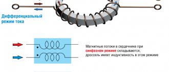
In the OT series, people thought and made a cunning drive: a person rotates an uneven shaped cam. On one side it protrudes more, on the other - less. And with this protrusion the cam presses on the rod, which, in turn, moves the contacts. And in order for the cam to rotate jerkily, it is equipped with a spring. And to make it SEVERE - there are already 4 springs! I say: it couldn’t have happened without Chelyabinsk, obviously!
Mechanism of operation of OT series switches
This is how this cam is placed and presses on the white rod =)
Mechanism operation: the cam, turning, presses on the contact rod
This is how the cable clamps are designed. In the 25-amp version, these are simply flattened plates that press the cable. In the 63 amp version, the clamps are more brutal and have a larger clamping area. Pay attention to this little detail: the place where the thread for the screw is cut has a thickening so that even a drunken ZhEK electrician will not tear off this thread if he ever has to install such a switch. Well, there is no need to talk about the fact that all the screws do not fall out.
One of the terminals of the 25A OT switch
Let's open the switch further and check out the contact groups. Actually, everything can be seen this way. Contactors/starters probably have this contact design. When each contact is also spring-loaded. Well, breaking the chain here is done like an adult: on both sides, and all external contacts are stationary. You can serve whatever you want, however you like.
Switch contact group ABB OT25
You don't even need to draw conclusions. If you want non-standard functions (reversing switch, etc.), this is definitely the OT series. If you want an evil switch that can be turned 50 times a day and also under load, this is also the OT series.
But if you are assembling a small shield for a frail input, and every module is important to you (this also happens), then you can install the E200. And if a housewife will use the shield, also look towards the E200. But the statistics are inexorable: approximately one switch out of 15 may be defective.
And I’ll also say a few words about the reversing switches of the OT series . I have nowhere to take a special photo of it right now, so I’ll give you links to my own photos of the shields.
, here they are in Igor Valentinovich’s window
and here they are in the mega-shield for the cottage:
.
A reversing switch is a switch from one position to another. They are usually used to switch power supplies. Say, from one input to another or from the network to a generator. The only difference is that for safety and to completely turn off the line, there is a third position when no input is selected.
Mnemonically, this can be written as follows: I-OFF-II. And in theory, such switches should have three groups of contacts: General, I and II. But in the OT series we are faced with a feature that causes a brain explosion in uninitiated people accustomed to standard switches. In the OT series, the reversing switch consists of two conventional switches placed side by side and connected by a special drive. The drive has three positions (the same I-OFF-II) and controls these two switches. In position “I” only the left switch is turned on. In position “II” - only the right one. And as such, they do not have a common contact, and you need to make it yourself by connecting the switches on one of the sides in parallel.
The photo clearly shows how it was done. Here this switch switches the power between the generator and the mains. The network and the generator are connected to the upper contacts of two circuit breakers of the assembly, and the lower contacts are connected in parallel. And so that the circuit is universal, and it is possible to connect not a generator (maybe it is not needed), but a stabilizer or UPS, then two blocks of terminal blocks are made. One is to the switch, the second is to switch “II”. We will supply power before the switch to the stabilizer/UPS, and to switch “II” we will supply clean power. And then the same switch works for us as a correct and high-quality bypass, without any fuss.
I especially note an important point! Reversible switches take up twice as much space in height and come without a handle included!! When choosing a shield for them, BE CAREFUL! They won’t fit into regular Europa/Uniboxes: the panel door won’t close! I haven’t tested it in UK500, but they fit in Europa IP65 and AT/U without any problems!
In order not to climb through catalogues, I give information for reference (my popular items):
1SCA105338R1001 ABB OT63F3C Reversing switch up to 63A 3-pole (without handle) 1SCA108319R1001 ABB OHBS3/1 Control handle (black) direct mounting for switches OT16..125F 1SCA108688R1001 ABB OHRS3/1 Control handle (red naya) direct mounting for circuit breakers OT16..125F
That's all. Let's move on! =)
UPDATE : There is one more addition that I forgot about, but they reminded me: it is also important that switches with a nominal value of 16, 25, 40A have a height less than the height of the panel and, if you put them in a regular panel on a DIN rail, then they will be located somewhere inside the shield and will be completely inconvenient to use. Therefore, the most convenient rating is 63A switches, which fit perfectly into the panel.
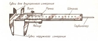
Switch device
The device of the switch
The switch is a simple but well-thought-out device, thanks to which it has become widespread in electrical work.
Switch device:
- Base. Designed for reliable fastening of device components and mechanisms.
- Fixed contacts, rigidly fixed to the base and having terminals for connecting cable wires. They are double plates with elasticity.
- Fixed bracket for fastening a moving element. Made from durable, abrasion-resistant material.
- A movable contact made in the shape of a knife or fork for a consumable insert.
- A handle equipped with an insulating pad at the gripping end.
Depending on the number of directions and poles, a three-phase electric switch has 3 output and 3/6 input contact terminals. The design of the device is designed to firmly hold contacts regardless of their weight and vibration level. All parts through which current is passed are made of a special copper alloy M1. Protection against corrosion is carried out by coating them with tin.
Block switches vertical and horizontal
There is another type of switches where ceramic fuses are used as knives. This allows you to reduce the size of the switching device and combine switching with circuit protection. There are horizontal side-switches, where the fuses are next to each other, and also vertical, where the fuses are located one above the other, see photo below.
Sometimes switches of this type are also called multiblocks, but quite rarely. This design of the switch also provides a visible break. Some models can be switched under load; they have a lever drive installed, which disconnects the contact group with a jerk.
The difference between a switch and a disconnector
The difference between a switch and a disconnector is the mechanism for de-energizing the line, the distance between the separated ends and the presence of an electric arc.
The 380 V switch is used to disconnect devices that are under load - in the on state. The device makes it possible to carry out any manipulations with electrical equipment without de-energizing the entire residential property. In this case, the distance between the contacts is sufficient to prevent breakdown. The device housing covers the contacts, which prevents the ion arc from reaching adjacent parts or the ground line.
The purpose of the switch is to de-energize the entire facility. The load is first disconnected to prevent the contacts from melting. Emergency disconnection of the line is allowed in the event of an emergency - a fire, a break in the water supply or heating system.
Poles
Switches are single-pole, two-pole, three-pole. This characteristic indicates the number of wires that can be connected to the switch.
A single-pole switch disconnector allows you to connect one power wire and one outgoing wire. An example of such a device is a load switch
SHD201 made by ABB.
Bipolar devices are used where it is necessary to completely disconnect the network from voltage. They are relevant in circuits where a separate switch is provided for a single-phase electrical appliance. In this case, 4 wires are routed to the device - 2 power and 2 outlet. An example is the SHD 200 model produced by ABB.
Three-pole switches are used to protect a 3- or 4-wire network. Up to 6 wires are supplied to the model, of which 3 are phase and 3 are protected. This principle is implemented, for example, in switches SD203 C16 from ABB.
Four-pole devices allow you to connect 8 wires - 4 phase (of which 1 is neutral) and 4 outlets (also with one neutral). For example, like the SD204 C25 models from ABB.
Advantages and disadvantages
Reversing switch ABB OT63F3C 63A
Reversing switch-disconnectors are in demand in all sectors of economic activity.
The popularity of the products is based on the following advantages:
- Durability and reliability. The devices are resistant to mechanical stress and vibration.
- Long service life. High wear resistance of contacts and hinge joints ensures longevity of the devices even with frequent use. The device resource is 3000-5000 shutdowns.
- Safety. There is no risk of electric shock, explosion or fire.
- Minimum maintenance costs. Periodic lubrication of the joint is sufficient.
- Wide operating temperature range.
- Ecological cleanliness. The devices do not emit harmful substances into the environment.
- Compactness. Small dimensions make it possible to install several products in one panel.
- Affordable price.
- Simplicity and speed of installation.
The disadvantages of switches include the high level of switching overvoltage that occurs between the contacts at the moment of the minimum distance between them. This requires the use of effective measures to protect switching points.
Modifications
The first switches were of the changeover type. They were a switch with two positions - on and off. The changeover switch is used for switching a large number of electrical lines. Modifications of the changeover switch appear in modern electrical networks.
Disconnect switch. Such devices are small in size, have a short handle, and are supplied in a protective case. This principle is implemented in the changeover switch-disconnector VR32-31F-V71250-100A manufactured by KEAZ:
Rotary drive switches . Devices with a rotary handle are simple, reliable and have high mechanical strength. Their knives begin to move by turning a lever. These include, for example, the OT25F3 3p 25A switch manufactured by ABB.
Modular switches mounted on a DIN rail . Essentially, this is a switch that serves to protect equipment from overload and short circuit. For example, a modular two-pole switch SHD202 C25 manufactured by ABB.
Reversible switches. Used to switch system power between two independent devices. For example, between a power line and an autonomous power generator. An example of a device is OT100F3C 3p 100A manufactured by ABB.
Using a switch
Reversing switch in the distribution board
Scope of application:
- transformer booths;
- local step-down substations;
- entrance panels in the entrances of houses;
- industrial equipment in workshops;
- warehouses;
- public places;
- offices, offices and other institutions;
- catering establishments;
- private houses, dachas, cottages.
Before installation, a schematic drawing is made, which indicates the line, consumers and switches. You can use a computer program to make a drawing. A single-phase or three-phase switch is located in a panel that prevents access to it by unauthorized persons.
Main types
By marking the switch on the panel you can find out its type, device and potential capabilities.
The following decryption has been established:
- P - switch;
- P - switch;
- P - front connection of wires;
- B - side handle;
- C - central lever;
- numbers - the first (1-3) number of poles, (4-6) current strength (1 - 100 A, 2 - 250 A, 4 - 400 A and 6 - 600 A).
Different types of switches are classified according to the following areas:
- Current strength (100-1000 A).
- Number of poles (1-3).
- Type of current (direct, alternating).
- Control method (side, center).
- Method of connecting wires (front, rear).
- Current directions (1-3).
- The presence of a fuse in the knife.
- Availability of arc extinguishing system.
- Installation of auxiliary contacts.
- Degree of protection (open and closed version).
- Operating temperature (hot, cold, moderate).
When choosing a product, it should be taken into account that only de-energized circuits can be disconnected with devices with a front handle. For lines under load, devices with a side handle are used.
Rated current
Rated current is an indicator that characterizes the parameters of the electrical network with which this switch will work. This characteristic is expressed in amperes and is present in the marking of the device:
- 16A – OT16F3 3p 16A, SHD202 C16 (ABB);
- 20A – VN-32 2P 20A (IEK);
- 25A – OT25F3 3p 25A, SHD202 C25 (ABB), VN-32 2P 25A (IEK);
- 32A – SHD202 C32 (ABB);
- 40A – OT40F3 3p 40A, SHD201 C40 (ABB);
- 50A – SHD201 C50 (ABB);
- 63A – OT63F3 3p 63A, SHD201 C63 (ABB);
- 80A – OT63F3 3p 63A (АВВ);
- 100A – OT100F3C 3p 100A (ABB), 100-IP54-U3-004-Uzola;
- 125A – OT125F3C 3p 125A (АВВ);
- 250A – 250-IP54-UZ-001-Uzola;
- 400A – YaBPVU-400-IP54-U3 (Uzola);
- 630A – YARP-630-IP54-U3-Uzola, VR32-39F-V31250-630A-UHL3 (KEAZ).