Inch thread parameters
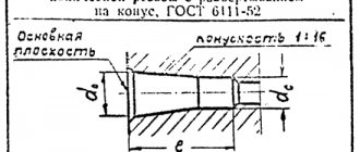
Requirements for standard parameters of cylindrical inch threads are specified in GOST 6111-52. Basic characteristics of threaded connections such as pitch and diameter are also indicated here.
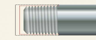
- The outer diameter is the distance between the top points of the threaded ridges on opposite sides of the pipe. To find it out, you can use a ruler or caliper.
- Internal diameter is the distance from one lowest point of the cavity between the threaded ridges to the other, located on the opposite side of the pipe.
Basic parameters of inch threads
Knowing the outer and inner diameters of an inch thread, you can calculate the height of its profile. To do this, it is enough to determine the difference between the diameters.
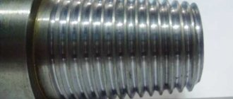
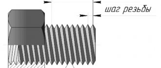
The pitch of an inch thread refers to the distance that separates two adjacent crests (or two adjacent valleys). The thread pitch usually does not exceed 3 mm, so high-precision rulers are used to measure it.
Measuring the pitch of an inch thread
Differences between inch and metric threads
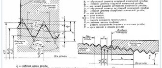
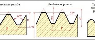
Metric and inch threads differ in the number of turns per thread pitch and different angles of inclination at the apex. For inch threads it is sharper and equals 55 degrees. The rest of the differences come from this.
- Due to the sharper angle of inclination, the profile of the threaded ridges changes. Inch joints have longer ridges but are less wide. The metric profile has more balanced ridges in shape (wider and not as long).
- Due to the difference in profiles, it is not possible to connect parts with metric and inch threads. The fasteners will be very fragile and leaky, which may lead to leakage of liquids during transportation.
Differences in the profile of imperial, metric and pipe threads
Where is which one used?
Metric threads are used all over the world in various fields of activity. They are used in the production of fasteners, household appliances, industrial equipment, automobiles, and plumbing products.
Interesting: Types of metal cutting equipment
Inch threads are actively used in the USA, Canada, and some European countries. The only area of activity where they replace metric connections is plumbing.
Inch threaded connections have one important feature that metric threads do not have. When measuring tenths of a millimeter, various difficulties may arise and the accuracy of the measurement may decrease. The measurement process for inch connections uses ¼ inch increments. This improves the accuracy of measurements and simplifies designation.
Table of sizes of inch and metric threads
You can find out how the sizes of metric threads relate to the sizes of inch threads using the data in the table below.
Similar sizes of metric and various varieties of inch threads in the range of approximately Ø8-64 mm
Types of inch threads
Inch threads can be cylindrical or conical. With a cylindrical connection, the dimensions of the outer and inner diameters are maintained along the entire length of the spare part. The threaded pitch has a fixed size, and the number of threads is related to the pitch. Spare parts with such a connection are more durable and reliable.
With a tapered connection, the thread has a variable diameter. The most widely used threads are those with a tapering diameter, in which the diameter at the base is larger than the diameter at the tail of the spare part. Parts with a tapered connection are often double marked, indicating not only the initial but also the final diameter. Inch tapered threads are stronger and wear out more slowly, but they are more difficult to apply, and errors in the procedure can seriously deteriorate the quality of the connection.
Inch thread cutting technology
Inch pipe thread cutting can be done manually or mechanically. Let's describe both options.
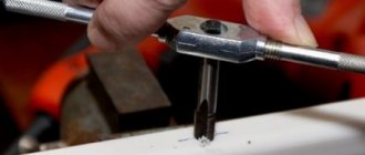
Method 1: Tapping by hand
Inch threads are cut manually using a tap (internal thread) or a die (external thread). Operations are carried out in the following sequence.
- The pipe is clamped in a vice, and the tool is fixed: if it is a tap, then in the driver, if it is a die, then in the die holder.
- The die is put on the end of the pipe, the tap is inserted into its lumen.
- The tool is screwed into the pipe or screwed onto its end by rotating a knob or die holder.
- If necessary, to achieve a more accurate result, the procedure for cutting inch threads is repeated several times.
Method 2: Cutting threads on a lathe
The mechanical method involves cutting inch threads on a lathe. During the work you need to adhere to this algorithm.
- The pipe is clamped in a machine chuck, on the support of which a thread-cutting tool is installed.
- The end of the pipe is chamfered with a cutter, after which the cutting speed is adjusted.
- After bringing the cutter to the surface of the pipe, the machine turns on the threaded feed.
It is possible to cut inch pipe threads on a lathe only if the products have a sufficient reserve of rigidity and strength. The mechanical method guarantees an accurate and high-quality result, but requires great skills from the master.
Slicing methods
Inch threads can be applied to almost any cylindrical or conical parts. These could be pipes, bolts, special workpieces, and so on. Basic cutting methods:
- Hand cutting. With this processing method, cutting is carried out using a tap or die. The main advantage of the technology is the high mobility of the technique. The worker does not need to carry the workpiece to the cutting workshop - he can take with him all the necessary tools to perform the cutting on site. For cutting, it is recommended to fix the workpiece in a vice. Then you need to put a die on the end of the pipe or insert a tap into the inside of the pipe. After this, you need to turn the tool to create internal or external threads on the part. To make the job easier, it is recommended to use pliers or similar equipment. If necessary, manual cutting can be done in several passes (this will increase the quality of processing).
- Application of lathes. In this case, processing is carried out using a tapping cutter, which can be used to create external or internal threads. The machines are usually large in size and electrically powered, which makes them not very mobile. For cutting, the workpiece is fixed in the machine chuck, and the cutter is inserted into the support. After turning on the machine, the part is cut, and with the help of the caliper the speed of work and the direction of feed of the cutter are adjusted. Modern lathes can be equipped with a CNC panel, which allows you to automate a number of procedures and simplify the task for the worker.
Each technology has its own pros and cons. Manual cutting is recommended for use in case of a small number of parts (home production or small workshop). Lathe cutting is suitable for large or medium-sized industries with high production load. Before carrying out work, it is necessary to evaluate the parameters of the product (thickness, rigidity, dimensions). In the case of large large-sized parts, a machine-tool processing method is recommended, since manual cutting may be impossible for objective reasons (the worker will get tired quickly, which will reduce the cutting speed).
Accuracy classes and rules for marking inch threads
Inch threads according to GOST can correspond to one of the accuracy classes: 1, 2 or 3. The letter A (corresponds to external thread) or B (internal) occupies the adjacent place with the number indicating the accuracy class. Note that the 1st class of accuracy corresponds to the coarsest threads, and the 3rd class is the most precise, and the most stringent requirements are imposed on them.
To understand what parameters a specific threaded element corresponds to, you need to understand the symbols that are printed on it. The label contains the following information:
- nominal inch thread size;
- number of turns per inch of length;
- group;
- accuracy class.
The marking is applied to the part itself or packaging with parts and is an alphanumeric code of the following type: T1 T2 X Y1 Y2 - Z.
This code is deciphered as follows.
- T1 - the parameter indicates the category of the threaded spare part and can have several values: M (metric thread), MK (conical), Tr (trapezoidal single-start), S (thrust single-start), G (cylindrical pipe).
- T2 - indicates the outer diameter of the spare part; for inch threads it is indicated in inches.
- X is a separator symbol that does not carry any semantic load, but is required to be applied according to GOST.
- Y1 is the width of the thread pitch, which is indicated in millimeters even on inch threads. In rare cases, a parameter may be indicated in inches, but then two notches are placed next to the number, which indicate that we are looking at inches.
- Y2 is the direction of the threaded screw. There is a left-hand thread, the parameter is designated as LH. If it's on the right, they let him through.
- - also refers to delimiter characters that separate the main part of the code from the Z parameter.
- Z is a parameter that indicates the thread accuracy class. Can take the form of designations 4k, 6h, 6E, 8G, 8D, etc.
An example of a symbol for an inch thread
Interpretation of inch thread markings
Let us look at the designation of inch threads in the technical documentation using the example of marking G 2” LH-2-40.
- G - indicates that the pipe thread is cylindrical.
- The number 2 indicates the outer diameter size in inches.
- LH - these letters indicate that the thread is left-handed.
- Number 2 informs about the accuracy class.
- The number 40 indicates the screw length.
Steel pipe diameters
In practice, there are diameters: nominal, internal, external, nominal bore. The values are indicated in the marking of pipes: for steel - in inches, for others - in millimeters. How to determine the diameter of a steel pipe in mm? Tables for matching the diameters of steel products will help with this.
The main characteristic of a steel pipe is its diameter. This parameter determines the purpose, length of the pipeline, composition and physical characteristics of the transported substance. All diameter values are standardized and regulated by regulatory documents - standard sizes and requirements for products are regulated by GOST. Each type of pipe has its own standard.
What pipe diameters are there?
Theoretically, the diameter of the pipe is quite simply added to the formulas when determining any values. In practice, everything is more complicated - there are external, internal, nominal diameters, and wall thickness. What concepts are found and what do they mean:
- Conditional bore is the internal size of the pipe, determined in millimeters. Inches require rounding of values. Used for the correct joining of two products, for example, a pipeline and a fitting.
- Pipe wall thickness (S) is a physical quantity in millimeters on which many quality indicators of the product depend, including permeability and volume. Defined as the difference between the outer and inner diameter.
- Internal diameter is a physical quantity in millimeters, an important parameter for determining the passability of the highway. Formula for calculation: Dvn=Dn-2S
- Outer diameter (Dn) – has small dimensions (5...102 mm), medium – 103...426 mm, large – 427 mm and more.
- Nominal diameter is close by definition to the nominal diameter, but has more accurate values.
Numerical value of steel pipe diameters
A huge range of steel pipes for various purposes, designs, and types is presented in the form of tables, where the main parameters are:
- nominal diameter (or nominal diameter);
- outer diameter of the pipe;
- wall thickness.
Sometimes the weight of the product is entered into the table of diameters of steel pipes depending on its size, as well as the parameters of the nominal diameter.
Table values of steel pipe diameters
Tables are convenient to use when determining the exact dimensions of products when connecting them. For example, steel pipes are most often designated in inches - this dimension is accepted in many parts of the world. While polymer products are usually calculated in millimeters, which creates some difficulties when joining metal-plastic, cast iron, copper pipes with steel pipes in the water supply system. Diameter correspondence tables help determine the required dimensions of the joining elements and connect them correctly.
Table 1. Standard sizes of welded and seamless steel pipes
| Nominal pipe bore (Dy) mm | Thread diameter (G), inch | Pipe outer diameter (Dout), mm | ||
| Steel water and gas pipe | Seamless steel | Polymer | ||
| 10 | 3/8″ | 17 | 16 | 16 |
| 15 | 1/2″ | 21,3 | 20 | 20 |
| 20 | 3/4″ | 26,8 | 26 | 25 |
| 25 | 1″ | 33,5 | 32 | 32 |
| 32 | 1 1/4″ | 42,3 | 42 | 40 |
| 40 | 1 1/2″ | 48 | 45 | 50 |
| 50 | 2″ | 60 | 57 | 63 |
| 65 | 2 1/2″ | 75,5 | 76 | 75 |
| 80 | 3″ | 88,5 | 89 | 90 |
| 90 | 3 1/2″ | 101,3 | 102 | 110 |
| 100 | 4″ | 114 | 108 | 125 |
| 125 | 5″ | 140 | 133 | 140 |
| 150 | 6″ | 165 | 159 | 160 |
In Table 1, the parameters of the nominal bore in mm correspond to certain values of the internal diameter in inches. Please note how the outer diameter values differ for different types of pipes: seamless, electric-welded, metal-plastic. The difference can reach 17 mm.
How to correctly convert inches to millimeters
When converted to millimeters, the inch dimension is rounded up. Obviously, knowing the constant 1 inch is equal to 2.54 cm, you can independently calculate the diameter values according to the metric dimension.
But the problem is not how to calculate, but how to correctly determine the diameter. As practical measurements of steel pipes show, their marked diameter in inches does not correspond to the measured data in millimeters.
That is, the size indicated is 1” (corresponding to 25.4 mm), but in reality it turns out to be 33.5 mm. What is the reason for this discrepancy?
First of all, the internal diameter of the pipe is stamped in the designation. Secondly, the unit of diameter measurement is the dimension of the nominal bore (DN), which is indicated in integers.
Moreover, the size increases with the increase in the index (patency) of the pipe by 40-60% with each step.
The conditional diameter of the pipe corresponds to the internal clearance (nominal diameter) of the pipeline, but the final value is taken as an integer, rounded up. The conditional passage of the main line is standardized according to GOST 355-52.
To correctly select gas and water supply elements with inch markings, the best option would be to use tables. When connecting water and gas pipeline elements with metric and inch measurement systems (for example, steel pipelines with products made of copper, brass, polypropylene), it is important to take into account not only the internal, but also the external diameter.
Table 2. Values of diameters of steel pipes in accordance with inch dimensions
| Diameters, inch | Diameters, mm |
| 1/2 | d15 |
| 3/4 | d20 |
| 1′ | d25 |
| 1’/1/4 | d32 |
| 1’/1/2 | d40 |
| 2′ | d50 |
| 2’/1/2 | d65 |
| 3′ | d89 |
| 4′ | d100 |
Standard sizes of steel pipes
The generally accepted standard values for the internal diameter of steel pipes are determined by the following: 6, 10, 15, 20, 25, 32, 40, 50, 65, 80, 100, 110, etc. The nominal diameter of the pipe, calculated in inches, when converted to the metric system is rounded up to the nearest parameter from the standard series.
Table 3. Standard diameters of steel pipes
| Diameter category | Dimensions, mm |
| Small | 10; 10,2; 12; 13; 14; (15); 16; (17); 18; 19; 20; 21,3; 22; (23); 24; 25; 26; 27; 28; 30; 32; 33; 33,7; 35; 36; 38; 40; 42; 44,5; 45; 48; 48,3; 51; 53; 54; 57; 60; 63,5; 70; 73; 76; 88; 89; 95; 102; 108. |
| Average | 114; 127; 133; 140; 152; 159; 168; 177,8; 180; 193,7; 219; 244,5; 273; 325; 355,6; 377; 406,4; 426; (478); 530. |
| Large | 530; 630; 720; 820; 920; 1020; 1120; 1220; 1420. |
The most commonly used pipes are with diameters from 426 to 1220 mm. These are highways for water, gas, sewer, and irrigation systems.
Small-diameter pipes are used for water supply and heating in apartments of multi-storey and private buildings. Medium-diameter steel products are used for risers in urban infrastructure, as well as in the oil field industry. These are products with a diameter of ¾", for wiring inside ½".
Using the tables, the diameters of pipes made of plastic, copper, and brass are determined in the same way. The method of converting inch dimensions to metric is used when connecting products from different materials. If fittings are available, the installation of gas and water mains made of steel is simplified - these nuances are already taken into account in the connecting elements.