Repair and connection of pipes
Author temass
Date
Aug 19, 2016
0
1 606
Share
The classification of threaded connections is very extensive. Even if we consider a separate case, for example, pipe cutting in the shape of a cone, we cannot do without clarifying its features and types. Tapered threads are used quite widely, allowing the creation of reliable tight connections without welding. They are even called universal, since this is the only type of screw thread that allows connection to pipes of other shapes and sections.
- LiveJournal
- Blogger
Rare carving form
- Types and classification: inch Fanuc and others
- Tapered thread and its application: internal with standard gauge and natural screwing torque
- Tapered pipe thread standards according to GOST 6211 81: diameter and other dimensions
- Designations: tap, drawings
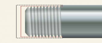
What is pipe thread
A thread is a groove that is applied mechanically or manually. It is characterized by the special height and relief of the spiral groove, its shape, the distance between the turns - the pitch. The thread can be applied to both the external and internal surface of the pipe. In addition, it may be present on a metal rod or conical surface.
The main purpose of pipe threads is to connect parts of the system. For a successful and tight connection, it is necessary that the grooves on both parts are identical in relief, pitch and shape. Moreover, they must be located on different surfaces - one inside, the other outside the pipe.
For reference: the above does not mean that the cutting can only be for fastening. Another type is the chassis. The latter is used in machine parts, where it is necessary not only to connect, but also to ensure the free movement of elements.
Why are pipe thread sizes in inches?
One of the most common questions that can be found on thematic forums is why all pipe dimensions are given in inches and not centimeters. The thing is that GOST, which began to operate in the post-Soviet space, was formed on the basis of the English standard - BSW. Its founder, design engineer Whitworth, created a screw profile back in the first half of the 19th century. The connection in which it could be used was supposed to be detachable. Whitworth positioned his profile as universal, as reliable as possible. Naturally, the engineer gave all dimensions in inches familiar to his country. When drawing up our own standard, they did not give up accurate measurements.
For reference: there is a concept “pipe inch”. It is not scientific and it is not in GOST, but in practice it is simply irreplaceable. Let us immediately note that the parameters of this unit do not coincide with the usual ones. Although there is a direct relationship between them. One unit of pipe inch is the outer diameter, but the inner diameter is also important, which is equal to one ordinary one. The explanation for this discrepancy is simple - all pipes are produced in an assortment (diameter, length, etc.), but the wall thickness is different for everyone and depends on the purpose of the product. This is where the concept of “conditional diameter” appears - we mean the internal one, which is paired with a given external standard.
Example: inch water pipe. The conventional unit is 25 mm with an external 33.6. But the real D can be either 27.1 (standard walls) or 25.6 (if the walls are thickened).
Types of pipe threads
Pipe threads allow you to connect elements and fittings in a non-welded way, while ensuring the tightness and reliability of the connection. As a rule, metal pipes are connected in this way, although recently it has also been used for plastic.
Types of pipe threads
What is a pipe thread? Its main features:
- special groove profile;
- the base is a triangle with an apex of 55 degrees, the edges are rounded;
- denoted by the Latin letter G;
- The digital marking after the letter indicates the nominal diameter of the pipe. According to the accepted standard, it is indicated in inches.
Pipe cylindrical thread - GOST 6357 81
Like other types, cylindrical pipe can be applied to the inner or outer surface of the pipe. Moreover, the standard contains an assumption under which a connection is possible when only the inner one is cylindrical, and the outer one is conical.
External cylindrical pipe thread
Pipe cylindrical thread internal
Legend
The standard designation is the Latin letter G. After the letter:
- digital indicator in inches - diameter of the nominal diameter of the pipe. For example - G 3⁄4”;
- letter designation of the type - right or left. It should be noted that no designations are provided for the right one. If the pipe thread is left-handed, it is marked LH;
- The next position in the pipe thread marking is marked with a hyphen. It denotes the accuracy class. There are two classes - A or B. The first is more “strict”; smaller permissible deviations are provided for it. In fact, the marking may look like this - G 1⁄2” LH - A;
- At the end of the pipe thread marking, the so-called make-up length is written. This is the area on which the thread is applied. For example: G 1”-B-35.
For reference: sometimes there may be a description for two connection elements at once. Example: G 3⁄4 “—A/B. The first place is always the description of the pipe, the second position is the coupling or the element that is connected.
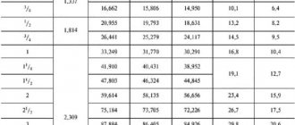
size table
Important parameters for cylindrical pipe threads are internal, external and average diameter. Depending on this parameter, the pitch is selected, that is, the number of turns that need to be cut for a reliable connection.
| Pipe size (inches) | D (mm) | D1 (mm) | D2 (mm) | Pitch (mm) | Number of spiral grooves per inch (pcs) |
| 1/16 | 7,724 | 7,142 | 6,561 | 0,907 | 28 |
| 1/8 | 9,728 | 9,14 | 8,52 | 0,907 | 28 |
| 1/4 | 12,15 | 12,302 | 11,446 | 1,337 | 19 |
| 3/8 | 16,662 | 15,86 | 14,96 | 1,337 | 19 |
| 1/2 | 20,96 | 19,74 | 18,632 | 1,814 | 14 |
| 3/4 | 2,91 | 21,749 | 20,537 | 1,814 | 14 |
| 5/8 | 26,440 | 25,277 | 24,188 | 1,814 | 14 |
| 7/8 | 30,201 | 29,038 | 27,889 | 1,814 | 14 |
| 1 | 33,249 | 31,775 | 30,298 | 2,309 | 11 |
| 1 1/8 | 37,9 | 36,419 | 34,989 | 2,309 | 11 |
| 1 3/8 | 42 | 40,422 | 38,552 | 2,309 | 11 |
| 1 1/2 | 44,4 | 42,899 | 41,355 | 2,309 | 11 |
| 1 3/4 | 47,8 | 46,32 | 44,842 | 2,309 | 11 |
| 2 | 53,746 | 52,267 | 50,78 | 2,309 | 11 |
| 2 1/4 | 59,614 | 58,125 | 56,325 | 2,309 | 11 |
| 2 1/2 | 65,77 | 64,369 | 62,39 | 2,309 | 11 |
| 2 3/4 | 75,185 | 73,269 | 72,369 | 2,309 | 11 |
| 3 | 81,532 | 80,365 | 78,258 | 2,309 | 11 |
| 3 1/2 | 87,887 | 85,255 | 84,258 | 2,309 | 11 |
| 3 3/4 | 93,980 | 92,896 | 92,365 | 2,309 | 11 |
| 4 | 100,332 | 98,369 | 103,589 | 2,309 | 11 |
| 4 1/2 | 106,69 | 105,32 | 110,256 | 2,309 | 11 |
| 5 | 113,040 | 111,85 | 124,328 | 2,309 | 11 |
| 5 1/2 | 125,732 | 124,852 | 135,693 | 2,309 | 11 |
| 6 | 138,420 | 136,985 | 160,259 | 2,309 | 11 |
For reference: the pitch size and number of turns are the same for several pipe thread sizes.
Tapered pipe thread - GOST 6211 81
Necessary in situations where special reliability of pipe fastening is required. From the name it is clear that the main feature of this type is application to a conical shape. The profile remains the same, but new values are added:
- working thread length - L1;
- length from edge to working plane - L2.
Tapered pipe thread - GOST 6211 81
Legend
Denoted by the Latin letter R. Labeling rules:
- only the letter R is external;
- combination Rc - conical, applied to the inner surface;
- combination Rp - internal, applied to a cylindrical surface.
Further designations follow the standard - size in inches, an indication of double-sidedness (if it is right-handed, there is no indication). If the marking describes a compound, the indicators are written as a fraction. For example: Rp/R 1”. The first position is always the external element of the system.
size table
| Pipe size (inches) | D (mm) | D1 (mm) | D2 (mm) | Pitch (mm) | Number of grooves per inch (pcs) | L1 | L2 |
| 1/16 | 7,723 | 7,768 | 6,475 | 0,907 | 28 | 6,5 | 4 |
| 1/8 | 9,728 | 9,657 | 8,098 | 0,907 | 28 | ||
| 1/4 | 13,15 | 12,21 | 11,345 | 1,337 | 19 | 9,6 | 6,1 |
| 3/8 | 16,662 | 15,322 | 14,278 | 1,337 | 19 | 10,1 | 6,6 |
| 1/2 | 20,996 | 19,345 | 18,567 | 1,814 | 14 | 13,4 | 8,4 |
| 3/4 | 26,441 | 25,765 | 24,567 | 1,814 | 14 | 14,6 | 9,9 |
| 1 | 33,249 | 31,190 | 30,291 | 2,309 | 11 | 16,2 | 10,4 |
| 1 1/4 | 41,9 | 40,123 | 38,952 | 2,309 | 11 | 19,2 | 12,7 |
| 1 1/2 | 47,803 | 46,564 | 44,845 | 2,309 | 11 | 19,7 | 12,7 |
| 2 | 59,614 | 58,943 | 56,566 | 2,309 | 11 | 23,6 | 15,9 |
| 2 1/2 | 75,567 | 73,485 | 72,657 | 2,309 | 11 | 26,6 | 17,3 |
| 3 | 87,995 | 85,934 | 84,993 | 2,309 | 11 | 29,6 | 20,5 |
| 3 1/2 | 100,657 | 98,657 | 97,309 | 2,309 | 11 | 31,4 | 22,2 |
| 4 | 113,867 | 111,41 | 110,082 | 2,309 | 11 | 35,3 | 25,4 |
| 5 | 138,986 | 136,76 | 135,542 | 2,309 | 11 | 40,2 | 28,7 |
| 6 | 163,546 | 162,984 | 160,823 | 2,309 | 11 | 40.2 | 28,7 |
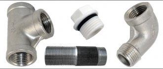
Conical inch thread - GOST 6111 52
This is a type of notch where all the protrusions are located on a conical surface in a spiral. This type of cutting is most often found in the production of couplings, elbows, and tees. Features of conical cutting:
- the tips and turns are blunted or cut off. This ensures a better fit and tightness of the connection;
- maximum cone diameter is 6 inches;
- the main cutting parameters - three diameters, stroke and pitch - can be found in the table. You don't have to calculate anything yourself.
Important: conical cutting is also used in cases where there are signs of wear, and it is not yet possible to replace the element. But such a measure is temporary. If the tightness of the connection is important, the worn element of the system will need to be replaced by selecting a cut of the required size according to the table.
Legend
On drawings and products, the cutting marking has the Latin letter K (sometimes you can find the designation NPT). Further decoding according to the standard - after the letter there is a size in inches, an indication of the right or left arrangement of the turns. In addition, the marking may contain an indication of external (A) or internal (B) cutting - after the size. At the end, the strength class (1-3) and make-up length may be indicated.
Conical inch thread - GOST 6111 52
size table
| Pipe cutting size (inch) | D (external) (mm) | D1 (medium) (mm) | D2 (internal) (mm) | Number of threads per 1 inch (pcs) | Pitch (mm) | Profile height (mm) |
| 3/16 | 4,77 | 4,14 | 3,13 | 24 | 1,25 | 079 |
| 1/4 | 6,25 | 5,43 | 4,89 | 20 | 1,33 | 0,92 |
| 5/16 | 8,72 | 7,58 | 6,27 | 18 | 1,58 | 1,01 |
| 3/8 | 9,81 | 8,93 | 7,54 | 16 | 1,67 | 1,25 |
| 7/16 | 11,52 | 10,23 | 8,23 | 14 | 1,98 | 1,38 |
| 1/2 | 12,38 | 11,18 | 10,59 | 12 | 2,24 | 1,46 |
| 9/16 | 14,49 | 13,67 | 11,756 | 11 | 2,24 | 1,46 |
| 5/8 | 15,55 | 14,32 | 13,34 | 10 | 2,43 | 1,57 |
| 3/4 | 19,28 | 17,23 | 15,93 | 9 | 2,61 | 1,76 |
Metric tapered thread - GOST 25229 82
Triangular cutting, the parameters of which are indicated in millimeters (mm). The profile angle is 60 degrees. Here we can distinguish two types of cutting - with large and small step sizes. The first option is the most common, since it protects the joint from wear.
Metric tapered thread - GOST 25229 82
Legend
In the first place are the letters (MK), then there are numerical designations of the step size and nominal diameter. For example: MK 24x1.5.
Size table according to GOST
| 1-2 row (D cuts) | P (step) | D | D1 | D2 | L | L1 | L2 |
| 6 | 1 | 6 | 5,35 | 4,917 | 8 | 2,5 | 3 |
| 8 | 1 | 8 | 7,35 | 6,917 | 8 | 2,5 | 3 |
| 10 | 1 | 10 | 9,35 | 8,917 | 8 | 2,5 | 3 |
| 12 | 1,5 | 12 | 11,026 | 10,376 | 11 | 3,5 | 4 |
| 14 | 1,5 | 14 | 13,026 | 12,376 | 11 | 3,5 | 4 |
| 18 | 1,5 | 18 | 17,026 | 16,376 | 11 | 3,5 | 4 |
| 20 | 1,5 | 20 | 19,026 | 17,376 | 11 | 3,5 | 4 |
| 22 | 1,5 | 22 | 21,026 | 20,376 | 11 | 3,5 | 4 |
| 24 | 1,5 | 24 | 23,026 | 22,376 | 11 | 3,5 | 4 |
| 27 | 2 | 27 | 25,701 | 23,835 | 16 | 5 | 6 |
| 30 | 2 | 30 | 27,701 | 36,845 | 16 | 5 | 6 |
| 33 | 2 | 33 | 31,701 | 30,835 | 16 | 5 | 6 |
| 36 | 2 | 36 | 34,701 | 33,835 | 16 | 5 | 6 |
| 39 | 2 | 39 | 37,701 | 36,335 | 16 | 5 | 6 |
| 42 | 2 | 42 | 40,701 | 39,835 | 16 | 5 | 6 |
| 45 | 2 | 45 | 43,701 | 43,835 | 16 | 5 | 6 |
| 48 | 2 | 48 | 46,701 | 45,835 | 16 | 5 | 6 |
| 52 | 2 | 52 | 50,701 | 49,885 | 16 | 5 | 6 |
| 56 | 2 | 56 | 53,701 | 53,835 | 16 | 5 | 6 |
| 60 | 2 | 60 | 58,701 | 58,835 | 16 | 5 | 6 |
TOLERANCES
3.1. Axial displacement of the main plane D1 l
2 external and D2
l
2 internal threads (Fig. 4) relative to the nominal location should not exceed the values specified in table. 3.
The displacement of the main plane is total, including deviations of the average diameter, pitch, angle of inclination of the side of the profile and cone angle.
3.2. The maximum deviations of the average diameter of the internal cylindrical thread must correspond to those indicated in the table. 3.
Crap. 4
Note. In the main plane, the average diameter has a nominal value.
Table 3
Dimensions in mm
| Thread size designation | Offset of the main thread plane | Maximum diameter deviations D 2 internal cylindrical threads | |
| ±D1l 2 | ±D2l 2 | ||
| 1/16 | 0,9 | 1,1 | ±0,071 |
| 1/8 | |||
| 1/4 | 1,3 | 1,7 | ±0,104 |
| 3/8 | |||
| 1/2 | 1,8 | 2,3 | ±0,142 |
| 3/4 | |||
| 1 | 2,3 | 2,9 | ±0,180 |
| 11/4 | |||
| 11/2 | |||
| 2 | |||
| 21/2 | 3,5 | 3,5 | ±0,217 |
| 3 | |||
| 31/2 | |||
| 4 | |||
| 5 | |||
| 6 | |||
Note. Limit deviations ±D1 l
2 and ±D2
l
2 do not apply to threads with lengths shorter than those indicated in table. .
3.3. It is allowed to connect an external conical thread with an internal cylindrical thread of accuracy class A according to GOST 6357-81.
3.4. Recommended maximum deviations of individual thread parameters are given in the reference appendix.
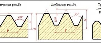
What are the main differences
The main differences between the types of pipe threads
Upon initial examination, it seems that it is difficult to distinguish one type of thread from another. This is not so; the main differences lie in the dimensions, profile angles, method of applying notches and the scope of application of such a connection.
Between pipe and inch
The main difference is the rounded cutting edges at the same profile angle.
Between pipe and metric
The main difference is the relief and size of the threaded ridge and depressions. In metric, an equilateral triangle (60 degrees) is used - all dimensions are the same. In a pipe one, the angle is smaller (55), and the dimensions may vary.
Another obvious difference is the units of measurement. Millimeters and inches are used accordingly.
In addition, when cutting pipes, the wall thickness of the product must be taken into account. The latter may vary depending on the operating pressure that the product can withstand and the scope of its application.
Between metric and cylindrical
The difference lies in the reduced profile angle (55 for cylindrical versus 60 for metric). In addition, dimensions are indicated in different units - millimeters and inches. The latter in a pair is applied to a cylindrical surface.
4. NOTATION
4.1. The thread symbol must include: letters ( R
- for tapered external thread,
Rc
- for tapered internal thread,
Rp
- for cylindrical internal thread) and thread size designation.
The symbol for left-hand threads is supplemented with the letters L H.
Examples of thread designations:
external pipe tapered thread 11/2: R
11/2
internal pipe tapered thread 11/2: Rc
11/2
internal pipe cylindrical thread 11/2: RP
11/2
left hand thread:
R
11/2
L.H.
;
Rc
11/2
L.H.
;
R.P.
11/2
LH.
4.2. A threaded connection is designated by a fraction, for example, or Rc
/
R
, the numerator of which indicates the letter designation of the internal thread, and the denominator - the external thread, and the thread size.
Examples of threaded connection designations:
pipe conical thread (internal and external);
; ;
internal pipe cylindrical thread (with tolerances according to this standard) and external pipe tapered thread:
; ;
internal pipe cylindrical thread of accuracy class A according to GOST 6357-81 and external pipe conical thread:
; .
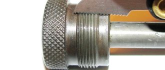
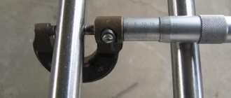
How to determine the pitch of an inch thread?
To understand whether the pitch size of inch cutting meets the requirements of GOST, you need to take measurements. You will need a template and tools. Any fitting can be used as a template, the step size of which exactly corresponds to the technical documentation. A bolt, the cutting pitch of which is measured, is screwed into the selected element. If the connection is tight, the notch pitch complies with GOST requirements.
You can determine the pitch of an inch thread using a thread gauge.
If the connection is loose or the bolt does not fit, the measurement is carried out with a thread gauge. The plate is tightly applied to the thread - a tight fit will indicate that the notches correspond to the size indicated on the body.
Slicing principles
When slicing, you need to take into account a number of features:
- cutting accuracy is determined by the parameters of the holes: diameter, perpendicularity of the center line to the surface of the workpiece, length;
- inch is cut with a profile angle of 60 degrees, and metric - 55;
- the tops and bottoms of inch threads, unlike metric threads, have more bluntness and have better tightness;
- to simplify the process, drilling a hole with a cylindrical drill is required; it is selected according to the smallest diameter;
- chamfering is required;
- When working, the tool must be lubricated to prevent overheating;
- when cutting, 2 turns are made forward, and then 1 turn back;
- the force on the cutting tool can be weakened after driving to the middle of the calculated length;
- Once the desired length is reached, the die can be removed by rotating in the opposite direction;
- Before finishing cutting, you need to do a rough cut.
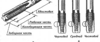
Conical taps are distinguished by an elongated shape of the intake part and an incomplete thread, which additionally plays a calibrating role. In the upper part they have a square cross-section; longitudinal grooves are made on the cutting part to remove chips.
Cutting:
- The workpiece is vertically fixed in a vice.
- Lubricant is applied to the tool.
- The tool is applied perpendicular to the center line for cutting threads, that is, strictly in a horizontal plane.
- Several turns are cut.
- The correctness of the work is checked. In case of misalignment, you need to remove the cutting tool, tap the part and repeat steps 3–4.
- Further cutting is carried out provided that the first turns are correctly positioned. You can check with a regular level.
- A thread is formed to the required length.
- At the end of the work, remove the chips and clean the tool from lubricant.
For cutting on lathes, heads with thread-cutting dies are used. A special design feature of the tool is the automatic spreading of the dies during operation. This ensures high machining precision and optimal productivity.
In some cases, knurling rollers are used. The cutting accuracy is lower than when using heads, and the complexity of the work is higher.
To set up a lathe, it is enough to set the spindle rotation speed to low and associate the caliper offset with it. Setting rule: one revolution of the spindle must correspond to the movement of the caliper by the distance of the thread pitch.
On lathes, adjustments are easy because there are many clutch combinations available on the gearbox. If necessary, it is possible to cut threaded grooves of non-standard sizes.