In the material:
- Features of choosing a drill for a tap
- Pre-hole diameter for metric taps
- How to choose a drill for a chipless tap
- Drill diameters for pipe (inch) taps
- How to choose drills for UNC/UNF taps
- Drill diameters for trapezoidal threads
- Where to buy drills for cutting rough threads for a tap?
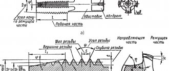
The tap is used for cutting internal threads and is a screw with cutting edges. However, before you tap the internal threads, you need to prepare a rough hole. For this, drills are used, which gives rise to a new problem, the essence of which is to select the correct drill diameter. The fact is that a hole with a larger diameter will lead to beveled threads, and a smaller one will ruin the tap. The thread pitch of taps can be different, and each pitch corresponds to a suitable drill diameter.
In this article we provide tables with drill diameters for popular threads for metric, trapezoidal, pipe and chipless taps. Information is presented for major and minor step. In addition, we will touch on the main problems that may be associated with the selection of tools for drilling rough holes.
Features of choosing a drill for a tap
When choosing a drill for a tap, consider the following recommendations.
- Make sure that the drill fits the material being processed. For most threading operations, a tool made of high-speed steel containing cobalt is sufficient. However, if the material is harder, use a carbide drill bit.
- The rough hole needs to be countersinked and chamfered. This will allow for better centering of the tap and will also provide better entry into the threads of bolts, studs, etc.
- Take into account the properties of the material. For brittle, hard and soft, tough metals, the hole diameter will be different. Thus, the diameter of a drill for an M8 thread in a soft material will be 6.8 mm, and in a hard material - 6.7 mm.
In this article you will find links to GOST standards that indicate which drill to choose for the existing tap. The documents specify hole sizes of varying precision and maximum diameter deviations. The diameters of holes for cutting threads in soft and viscous materials are also given here.
Types of instruments
The appropriate tool is selected depending on the characteristics of the material being processed, the required productivity and other parameters. Using different types of taps, you can cut metric or inch internal threads with a cylindrical or conical profile.
According to the method of conducting the process, models are distinguished:
- Pass-through (universal) . Their working part consists of three zones. The first performs rough cutting, the second – intermediate, and the third – finishing.
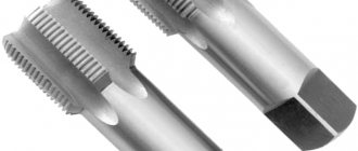
- Complete . To perform a full range of work, several tools are used - for roughing, intermediate and finishing cutting. The sets consist of three taps, less often of two (for roughing and finishing). For processing particularly strong metals, kits with 5 tools are used.
The tool is made of two types: for processing holes manually or using metal-cutting equipment.
- Machine-manual . Has a square shank. Works complete with a holder with two handles - a knob.
- Machine . Installed in the chuck of metalworking machines of various types.
Taps of different designs are used for cutting threads in blind and through holes:
- For non-passable holes, use a complete tool without a conical tip. The work is usually done with a crank.
- In through holes, threads are made using taps with a conical tip. Most often these are varieties of universal type tools.
The channels for removing chips have different shapes: straight, screw, shortened.
Chip channels of any shape are suitable for processing materials of low hardness. To tap threads in high-hardness materials, such as stainless and heat-resistant steels, use only a tool in which the cutting segments are staggered.
Pre-hole diameter for metric taps
We suggest that you familiarize yourself with GOST standards for metric threads, which are cut with standard taps of the most popular sizes M3, M4, M5, M6, M8, M10 and M12 with a basic pitch.
Brief table for the most common coarse pitch metric thread sizes:
| Tap (thread/main pitch) | Hole diameter (⌀ drill), mm |
| M3x0.5 | 2,5 |
| M4x0.7 | 3,3 |
| M5x0.8 | 4,2 |
| M6x1.0 | 5,0 |
| M8x1.25 | 6,8 |
| M10x1.5 | 8,5 |
| M12x1.75 | 10,2 |
| M14x2.0 | 12,0 |
| M16x2.0 | 14,0 |
| M18x2.5 | 15,4-15,6 |
| M20x2.5 | 17,4-17,6 |
Detailed table of drill sizes for metric threads, main pitch (DIN 13/GOST 24705):
| M | Pitch, mm | Internal diameter of nut thread, mm (additional according to ISO2 – 6H) | Drill diameter, mm (according to DIN336) |
| 1 | 0,25 | *0,774 | 0,75 |
| 1,1 | 0,25 | *0,874 | 0,85 |
| 1,2 | 0,25 | *0,974 | 0,95 |
| 1,4 | 0,3 | *1,128 | 1,1 |
| 1,6 | 0,35 | 1,321 | 1,25 |
| 1,8 | 0,35 | 1,521 | 1,45 |
| 2 | 0,4 | 1,679 | 1,6 |
| 2,2 | 0,45 | 1,838 | 1,75 |
| 2,5 | 0,45 | 2,138 | 2,05 |
| 3 | 0,5 | 2,599 | 2,5 |
| 3,5 | 0,6 | 3,010 | 2,9 |
| 4 | 0,7 | 3,422 | 3,3 |
| 4,5 | 0,75 | 3,878 | 3,7 |
| 5 | 0,8 | 4,334 | 4,2 |
| 6 | 1 | 5,153 | 5,0 |
| 7 | 1 | 6,153 | 6,0 |
| 8 | 1,25 | 6,912 | 6,8 |
| 9 | 1,25 | 7,912 | 7,8 |
| 10 | 1,5 | 8,676 | 8,5 |
| 11 | 1,5 | 9,676 | 9,5 |
| 12 | 1,75 | 10,441 | 10,2 |
| 14 | 2 | 12,210 | 12,0 |
| 16 | 2 | 14,210 | 14,0 |
| 18 | 2,5 | 15,744 | 15,5 |
| 20 | 2,5 | 17,744 | 17,5 |
| 22 | 2,5 | 19,744 | 19,5 |
| 24 | 3 | 21,252 | 21,0 |
| 27 | 3 | 24,252 | 24,0 |
| 30 | 3,5 | 26,771 | 26,5 |
| 33 | 3,5 | 29,771 | 29,5 |
| 36 | 4 | 32,270 | 32,0 |
| 39 | 4 | 35,270 | 35,0 |
| 42 | 4,5 | 37,799 | 37,5 |
| 45 | 4,5 | 40,799 | 40,5 |
| 48 | 5 | 43,297 | 43,0 |
| 52 | 5 | 47,297 | 47,0 |
| 56 | 5,5 | 50,796 | 50,5 |
| 60 | 5,5 | 54,796 | 54,5 |
| 64 | 6 | 58,305 | 58,0 |
| 68 | 6 | 62,305 | 62,0 |
*Tolerance range according to ISO1 – 4H.
Detailed table of drill sizes for fine pitch metric threads (DIN 13/GOST 24705):
| MxStep | Internal diameter of nut thread, mm (additional according to ISO2 - 6H) | Drill diameter, mm >(according to DIN336) | MxStep | Internal diameter of nut thread, mm (additional according to ISO2 - 6H) | Drill diameter, mm >(according to DIN336) | |
| 2×0,25 | *1,774 | 1,75 | 24×1 | 23,153 | 23 | |
| 2,2×0,25 | *1,974 | 1,95 | 24×1,5 | 22,676 | 22,5 | |
| 2,3×0,25 | 2,071 | 2,05 | 24×2 | 22,210 | 22 | |
| 2,5×0,35 | *2,184 | 2,15 | 25×1 | 24,153 | 24 | |
| 2,6×0,35 | 2,252 | 2,2 | 25×1,5 | 23,676 | 23,5 | |
| 3×0,35 | *2,684 | 2,65 | 26×1,5 | 24,676 | 24,5 | |
| 3,5×0,35 | *3,184 | 3,15 | 27×1,5 | 25,676 | 25,5 | |
| 4×0,35 | *3,684 | 3,65 | 27×2 | 25,210 | 25,0 | |
| 4×0,5 | 3,599 | 3,5 | 28×1,5 | 26,676 | 26,5 | |
| 5×0,5 | 4,599 | 4,5 | 28×2 | 26,210 | 26,0 | |
| 6×0,5 | 5,599 | 5,5 | 30×1 | 29,153 | 29,0 | |
| 6×0,75 | 5,378 | 5,2 | 30×1,5 | 28,676 | 28,5 | |
| 7×0,75 | 6,378 | 6,2 | 30×2 | 28,210 | 28,0 | |
| 8×0,5 | 7,599 | 7,5 | 32×1,5 | 30,676 | 30,5 | |
| 8×0,75 | 7,378 | 7,2 | 33×1,5 | 31,676 | 31,5 | |
| 8×1 | 7,153 | 7,0 | 33×2 | 31,210 | 31,0 | |
| 9×0,75 | 8,378 | 8,2 | 34×1,5 | 32,676 | 32,5 | |
| 9×1 | 8,153 | 8,0 | 35×1,5 | 33,676 | 33,5 | |
| 10×0,5 | 9,599 | 9,5 | 36×1,5 | 34,676 | 34,5 | |
| 10×0,75 | 9,378 | 9,2 | 36×2 | 34,210 | 34,0 | |
| 10×1 | 9,153 | 9,0 | 36×3 | 33,252 | 33,0 | |
| 10×1,25 | 8,912 | 8,8 | 38×1,5 | 36,676 | 36,5 | |
| 11×1 | 10,153 | 10,0 | 39×1,5 | 37,676 | 37,5 | |
| 12×0,75 | 11,378 | 11,2 | 39×2 | 37,210 | 37,0 | |
| 12×1 | 11,153 | 11,0 | 39×3 | 36,252 | 36,0 | |
| 12×1,25 | 10,912 | 10,8 | 40×1,5 | 38,676 | 38,5 | |
| 12×1,5 | 10,676 | 10,5 | 40×2 | 38,210 | 38,0 | |
| 13×1 | 12,153 | 12,0 | 40×3 | 37,252 | 37,0 | |
| 14×1 | 13,153 | 13,0 | 42×1,5 | 40,676 | 40,5 | |
| 14×1,25 | 12,912 | 12,8 | 42×2 | 40,210 | 40,0 | |
| 14×1,5 | 12,676 | 12,5 | 42×3 | 39,252 | 39,0 | |
| 15×1 | 14,153 | 14,0 | 45×1,5 | 43,676 | 43,5 | |
| 15×1,5 | 13,676 | 13,5 | 45×2 | 43,210 | 43,0 | |
| 16×1 | 15,153 | 15,0 | 45×3 | 42,252 | 42,0 | |
| 16×1,5 | 14,676 | 14,5 | 48×1,5 | 46,676 | 46,5 | |
| 18×1 | 17,153 | 17,0 | 48×2 | 46,210 | 46,0 | |
| 18×1,5 | 16,676 | 16,5 | 48×3 | 45,252 | 45,0 | |
| 18×2 | 16,210 | 16,0 | 50×1,5 | 48,676 | 48,5 | |
| 20×1 | 19,153 | 19,0 | 50×2 | 48,210 | 48,0 | |
| 20×1,5 | 18,676 | 18,5 | 50×3 | 47,252 | 47,0 | |
| 20×2 | 18,210 | 18,0 | 52×1,5 | 50,676 | 50,5 | |
| 22×1 | 21,153 | 21,0 | 52×2 | 50,210 | 50,0 | |
| 22×1,5 | 20,676 | 20,5 | 52×3 | 49,252 | 49,0 | |
| 22×2 | 20,210 | 20,0 | 63×1,5 | 61,676 | 61,5 |
Important!
In order to understand without a table which drill for the tap is optimal, you need to subtract its pitch from the nominal thread diameter. Let's consider the method using an M10x1.5 thread as an example.
- The nominal thread diameter is 10 mm.
- Step - 1.5 mm.
- We subtract the pitch from the thread diameter: 10 – 1.5 = 8.5 mm.
- We get the drill diameter: 8.5 mm.
It is allowed to round the result up. For example, round 9.75 to 9.8 mm. However, this method allows you to find out only an approximate value and is more suitable for domestic needs. In production, specialists rely on the tables specified in GOSTs and take into account the tolerances and features of the material being processed.
How internal threads are cut - general information
The device is called a tap. It can be of two varieties - manual and machine, in accordance with the methods of making furrows. The material that is processed is metal, but not only it. There are also lightweight models that cut into plastic or wood. The last option cannot be called the most common.
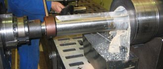
Factories use mechanized technology - metal drills make through holes (or a blind cavity), and after the blade, several turns are applied with a predetermined pitch. The advantage of this processing is high accuracy. Calculations are made using computer-aided design programs, then the data is entered into the control module - manually or using CNC. The second advantage is that skew of the spiral angle and errors are virtually impossible.
But at home and in small industries, a simpler, but less accurate procedure is often used - manually cutting internal threads with a tap. The work can be carried out on site; for this you need to buy the device itself and a drill to make a preliminary hole.
The tool resembles a herringbone shape due to the fact that the working surface is a ribbed blade. Structurally, the product is a rather complex configuration made of tool steel. This material is used because of its strength and ability to process most alloys, even cast iron. It is not very good to work only with hardened metal - it has internal stresses, therefore it is considered fragile and can crumble during the cutting process.
How to choose a drill for a chipless tap
Choosing a drill for a chipless tap, which is used to extrude threads, has its own difficulties associated with metal deformation. During processing, the metal is deformed both in the direction of the hole axis and in the opposite direction. For this reason, the rough hole for rolling is usually made of a larger diameter than for cutting with chips.
For example, to cut an M8 thread with a pitch of 1.25 mm, you need to take a tap with a diameter of 6.8 mm, and to obtain an M8x1.25 thread by rolling (extruding) you need to drill a rough hole with a diameter of 7.45 mm. First, let's look at the table values for metric chipless taps.
Table of hole sizes for rolling pins, metric thread, coarse pitch (DIN 13/GOST 24705):
| M | Thread pitch | Inner diameter of nut thread (add. ISO2 - 7H) | Min. mm | Max. mm | Rough hole diameter (calculated value), mm |
| 1 | 0,25 | *0,785 | 0,89 | 0,91 | 0,9 |
| 1,1 | 0,25 | *0,885 | 0,99 | 1,01 | 1,0 |
| 1,2 | 0,25 | *0,985 | 1,09 | 1,11 | 1,1 |
| 1,4 | 0,3 | *1,142 | 1,24 | 1,27 | 1,25 |
| 1,6 | 0,35 | *1,321 | 1,44 | 1,48 | 1,45 |
| 1,8 | 0,35 | *1,521 | 1,66 | 1,68 | 1,67 |
| 2,0 | 0,4 | *1,679 | 1,84 | 1,86 | 1,85 |
| 2,2 | 0,45 | **1,838 | 2,02 | 2,04 | 2,03 |
| 2,5 | 0,45 | *2,138 | 2,30 | 2,34 | 2,3 |
| 3 | 0,5 | 2,639 | 2,79 | 2,82 | 2,8 |
| 3,5 | 0,6 | 3,050 | 3,24 | 3,28 | 3,25 |
| 4 | 0,7 | 3,466 | 3,69 | 3,73 | 3,7 |
| 4,5 | 0,75 | 3,924 | 4,16 | 4,2 | 4,2 |
| 5 | 0,8 | 4,384 | 4,64 | 4,68 | 4,65 |
| 6 | 1 | 5,217 | 5,51 | 5,59 | 5,55 |
| 7 | 1 | 6,217 | 6,55 | 6,6 | 6,55 |
| 8 | 1,25 | 6,982 | 7,41 | 7,48 | 7,45 |
| 9 | 1,25 | 7,982 | 8,41 | 8,48 | |
| 10 | 1,5 | 8,751 | 9,28 | 9,37 | 9,35 |
| 11 | 1,5 | 9,751 | 10,28 | 10,37 | |
| 12 | 1,75 | 10,531 | 11,16 | 11,25 | 11,2 |
| 14 | 2 | 12,310 | 13,02 | 13,14 | 13,1 |
| 16 | 2 | 14,310 | 15,02 | 15,14 | 15,1 |
| 18 | 2,5 | 15,854 | 16,75 | 16,89 | 16,9 |
| 20 | 2,5 | 17,854 | 18,75 | 18,89 | 18,9 |
*Tolerance range according to ISO1 – 5H. **Tolerance range according to ISO2 – 6H.
Table of hole diameters for rolling taps, metric thread, fine pitch (DIN 13/GOST 24705):
| MxStep | Inner diameter of nut thread (add. ISO2 - 7H) | Min. mm | Max. mm | Rough hole diameter (calculated value), mm |
| 2×0,25 | *1,785 | 1,9 | 1,91 | |
| 2,2×0,25 | *1,985 | 2,1 | 2,11 | |
| 2,3×0,25 | *2,071 | 2,2 | 2,21 | |
| 2,5×0,35 | 2,201 | 2,36 | 2,38 | 2,37 |
| 2,6×0,35 | 2,252 | 2,46 | 2,48 | 2,47 |
| 3×0,35 | *2,701 | 2,87 | 2,89 | 2,88 |
| 3,5×0,35 | *3,201 | 3,37 | 3,39 | 3,38 |
| 4×0,35 | *3,701 | 3,87 | 3,89 | |
| 4×0,5 | 3,639 | 3,79 | 3,82 | 3,8 |
| 5×0,5 | 4,639 | 4,79 | 4,82 | 4,8 |
| 6×0,5 | **5,599 | 5,8 | 5,83 | 5,8 |
| 6×0,75 | 5,424 | 5,63 | 5,7 | 5,7 |
| 7×0,75 | 6,424 | 6,67 | 6,72 | 6,7 |
| 8×0,5 | **7,599 | 7,8 | 7,83 | |
| 8×0,75 | 7,424 | 7,67 | 7,72 | 7,7 |
| 8×1 | 7,217 | 7,51 | 7,6 | 7,55 |
| 9×0,75 | 8,424 | 8,67 | 8,72 | 8,7 |
| 9×1 | 8,217 | 8,55 | 8,6 | 8,6 |
| 10×0,5 | **9,599 | 9,8 | 9,83 | 9,8 |
| 10×0,75 | 9,424 | 9,67 | 9,72 | 9,7 |
| 10×1 | 9,217 | 9,51 | 9,6 | 9,55 |
| 10×1,25 | 8,982 | 9,41 | 9,48 | 9,45 |
| 11×1 | 10,217 | 10,55 | 10,6 | 10,6 |
| 12×1 | 11,217 | 11,52 | 11,61 | 11,55 |
| 12×1,25 | 10,982 | 11,43 | 11,5 | 11,45 |
| 12×1,5 | 10,751 | 11,29 | 11,38 | 11,35 |
| 14×1 | 13,217 | 13,55 | 13,61 | 13,6 |
| 14×1,25 | 12,982 | 13,43 | 13,5 | 13,45 |
| 14×1,5 | 12,751 | 13,29 | 13,38 | 13,35 |
| 15×1 | 14,217 | 14,55 | 14,61 | 14,6 |
| 15×1,5 | 13,751 | 14,26 | 14,36 | 14,35 |
| 16×1 | 15,217 | 15,55 | 15,61 | 15,6 |
| 16×1,5 | 14,751 | 15,29 | 15,38 | 15,35 |
| 18×1 | 17,217 | 17,55 | 17,61 | 17,6 |
| 18×1,5 | 16,751 | 17,29 | 17,38 | 17,35 |
| 18×2 | 16,310 | 17,02 | 17,14 | 17,1 |
| 20×1 | 19,217 | 19,55 | 19,61 | 19,6 |
| 20×1,5 | 18,751 | 19,29 | 19,38 | 19,35 |
| 20×2 | 18,310 | 19,02 | 19,14 | 19,1 |
| 22×1,5 | 20,751 | 21,26 | 21,36 | |
| 22×2 | 20,310 | 21 | 21,15 | |
| 24×1,5 | 22,751 | 23,26 | 23,38 | |
| 24×2 | 22,310 | 23,01 | 23,16 | 23,1 |
*Tolerance range according to ISO1 – 5H. **Tolerance range according to ISO2 – 6H.
Now let's see which drill to choose for a chipless tap for cutting inch pipe threads.
Diameter table for Whitworth pipe thread rolling taps (DIN ISO 228/1):
| G | Threads per inch | Outer thread diameter, mm | Nut thread internal diameter, max. mm | Min. mm | Max. mm | Rough hole diameter (calculated value), mm |
| G 1/16″ | 28 | 7,723 | 6,843 | 7,24 | 7,32 | |
| G 1/8″ | 28 | 9,728 | 8,848 | 9,24 | 9,32 | 9,25 |
| G 1/4″ | 19 | 13,157 | 11,890 | 12,48 | 12,56 | 12,55 |
| G 3/8″ | 19 | 16,662 | 15,395 | 15,99 | 16,06 | 16,06 |
| G 1/2″ | 14 | 20,955 | 19,172 | 20,02 | 20,12 | 20,05 |
| G 5/8″ | 14 | 22,911 | 21,128 | 21,97 | 22,07 | |
| G 3/4″ | 14 | 26,441 | 24,658 | 25,5 | 25,6 | |
| G 7/8″ | 14 | 30,201 | 28,418 | 29,26 | 29,36 | |
| G1″ | 11 | 33,249 | 30,931 | 32,05 | 32,18 | |
| G 1 1/8″ | 11 | 37,897 | 35,579 | 36,7 | 36,83 | |
| G 1 1/4″ | 11 | 41,910 | 39,592 | 40,72 | 40,84 | |
| G 1 3/8″ | 11 | 44,323 | 42,005 | 43,13 | 43,26 | |
| G 1 1/2″ | 11 | 47,803 | 45,485 | 46,61 | 46,74 | |
| G 1 3/4″ | 11 | 53,746 | 51,428 | 52,55 | 52,68 | |
| G 2″ | 11 | 59,614 | 57,296 | 58,42 | 58,55 |
How to cut threads
Thread cutting is quite simple, but requires special care when working and a precise sequence of actions. The choice of cutting method will determine the list of tools used and the features of preparing the part for processing.
You will need a technical reference book with data on the sizes of the tools used. The thread pitch can be found on the tap used.
Preparing for thread cutting
Cut the thread only after completing the preparatory work:
- in the directory they look for the necessary information on the diameters of cutting tools for further selection;
- collect the tools needed for work;
- use a core to mark the location of the hole for the internal thread, then drill it with a drill;
- for external cutting, prepare a workpiece of the required diameter on a milling machine and cut a chamfer;
- clean the surface of the workpiece from dirt and oil stains, then apply lubricant to it and the tool.
Thread cutting tool
Work order
Only after the preparatory work should you start processing the workpiece, since otherwise it will not be possible to cut the thread correctly. Step by step cutting is done like this:
- It is necessary to firmly fix the workpiece in a vice to prevent rotational or translational movements deviating from the original position.
- Depending on the type of thread, chamfer (external) or drill a through or blind hole using a drill. Drills with sharpening angles are used, depending on the hardness of the material, but not more than 1400.
- The hole needs to be chamfered with a countersink. The depth should be in the range of 0.5-1 mm, selected based on the dimensions of the part and the thread diameter.
- Cutting is performed with a tap or die. The cutting part must be lubricated.
- Cleaning the surface from chips using brushes.
When cutting, you need to sequentially use tools numbered 1 to 3, included in the kit. To increase the speed of work, it is not allowed to use large numbers without using the previous ones. The last number is used to form the finishing turns, without which the screw may jam when screwed in.
Drill diameters for pipe (inch) taps
Here is a table with the dimensions of rough holes for pipe threads.
| G | Thread pitch, mm | Number of threads per 1 inch | Diameter of drill bit for thread, mm | Threaded hole diameter, mm | ||
| Nominal | Limit deviations for accuracy classes | |||||
| A | B | |||||
| G1/8 | 0,907 | 28 | 8,7 | 8,62 | +0,1 | +0,2 |
| G1/4 | 1,337 | 19 | 11,5 | 11,5 | +0,12 | +0,25 |
| G3/8 | 1,337 | 19 | 15 | 15 | +0,12 | +0,25 |
| G1/2 | 1,814 | 14 | 18,75 | 18,68 | +0,14 | +0,28 |
| G5/8 | 1,814 | 14 | 20,75 | 20,64 | +0,14 | +0,28 |
| G3/4 | 1,814 | 14 | 24,25 | 24,17 | +0,14 | +0,28 |
| G7/8 | 1,814 | 14 | 28 | 27,93 | +0,14 | +0,28 |
| G1 | 2,309 | 11 | 30,5 | 30,34 | +0,18 | +0,36 |
| G1 1/8 | 2,309 | 11 | 35 | 35 | +0,18 | +0,36 |
| G1 1/4 | 2,309 | 11 | 39 | 39 | +0,18 | +0,36 |
| G1 3/8 | 2,309 | 11 | 41,5 | 41,41 | +0,18 | +0,36 |
| G1 1/2 | 2,309 | 11 | 45 | 44,9 | +0,18 | +0,36 |
| G1 3/4 | 2,309 | 11 | 51 | 50,84 | +0,18 | +0,36 |
| G2 | 2,309 | 11 | — | 56,7 | +0,18 | +0,36 |
| G2 1/4 | 2,309 | 11 | — | 62,8 | +0,22 | +0,43 |
| G2 1/2 | 2,309 | 11 | — | 72,27 | +0,22 | +0,43 |
| G2 3/4 | 2,309 | 11 | — | 78,62 | +0,22 | +0,43 |
| G3 | 2,309 | 11 | — | 84,97 | +0,22 | +0,43 |
| G3 1/4 | 0,907 | 11 | — | 91,07 | +0,22 | +0,43 |
| G3 1/2 | 1,337 | 11 | — | 97,42 | +0,22 | +0,43 |
| G3 3/4 | 1,337 | 11 | — | 103,77 | +0,22 | +0,43 |
| G4 | 1,814 | 11 | — | 110,12 | +0,22 | +0,43 |
| G4 1/2 | 1,814 | 11 | — | 122,82 | +0,22 | +0,43 |
| G5 | 1,814 | 11 | — | 135,52 | +0,22 | +0,43 |
| G5 1/2 | 1,814 | 11 | — | 148,22 | +0,22 | +0,43 |
| G6 | 2,309 | 11 | — | 160,92 | +0,22 | +0,43 |
Thread image on the drawing
In the drawings, the thread is depicted conditionally, according to the rules established by GOST 2.311-68.
The thread on the rod (external thread), regardless of its profile, is depicted by solid thick main lines along the outer diameter and solid thin lines along the internal diameter of the thread (Fig. 41).
A continuous thin straight line along the internal diameter of the thread is drawn along its entire length, including the chamfer. In views where a threaded rod is projected as a circle, its contour is outlined with a solid main line, and the internal diameter of the thread is depicted as a circular arc drawn by a thin line approximately 3/4 of the circle, open anywhere (just not on the center lines). When depicting a thread, a solid thin line is drawn at a distance of at least 0.8 mm from the solid main line and no more than the thread pitch (Fig. 41).
The line defining the thread boundary is drawn on the rod and in the threaded hole at the end of the full thread profile (before the start of the run). The thread boundary on the rod is drawn to the line of the outer diameter and is depicted with a solid thick main line (Fig. 41). When a thread on a rod or hole is shown in section, the boundary of the cut section of the thread is drawn with a dashed line.
Rice. 41. Image of external thread in the drawing
The thread in a hole in a longitudinal section is depicted by solid thin lines along the outer diameter and solid thick main lines along the internal diameter. The thread boundary is shown with a solid thick main line, bringing it to the outer diameter of the thread (Fig. 42).
Threads in a hole shown as invisible are shown as dashed lines.
If a threaded hole is projected in the form of a circle, then an arc of a circle approximately equal to 3/4 of the circle is drawn along the outer diameter of the thread with a thin line, open anywhere, just not on the center lines, and the contour of the hole (inner diameter of the thread) is outlined with a solid thick main line (Fig. 42). To determine the internal diameter of the thread (for drawing), its external diameter must be multiplied by 0.85, i.e.
Hatching in sections and sections is carried out to the line of the outer diameter of the thread on the rods and to the line of the internal diameter in the hole (Fig. 42), i.e., to a thick solid main line.
Chamfers on a threaded rod and in a threaded hole that do not have a special structural purpose are not shown in projection onto a plane perpendicular to the axis of the rod or hole. A solid thin line of the thread on the rod should intersect the chamfer boundary line.
Rice. 42. Image of internal thread in the drawing
The image of a threaded connection is composed of images of its constituent parts, as shown in Fig. 43. On sections of a threaded connection in images on a plane parallel to its axis, only the part of the thread that is not covered by the thread of the rod is shown in the hole.
Since threads of all types are basically standard, standard threads are depicted in the same way in the drawings. The type of thread and its main dimensions are indicated on the drawings by the inscription - the designation of the thread.
Rice. 43. Image of a threaded connection in the drawing
Before applying the thread designation, extension and dimension lines should be drawn. Designations of standard threads, except for pipe and conical threads, are written above the dimension line.
The designation of external threads (except for pipe and conical threads) is shown in Fig. 44, where 1
— thread length of full profile.
The designation of internal threads (except for pipe and conical threads) is shown in Fig. 45, where 1
— thread length of full profile.
The designation of conical pipe threads is applied as shown in Fig. 46, cylindrical pipe, as shown in Fig. 47.
According to GOST 16093-2004, the accuracy of threads is indicated by a tolerance field, where the number indicates the degree of accuracy, and the letter indicates the main deviation. For example, for a thread on a rod 4/g, 6g
,
8d,
and in the hole -
4H, 1G.
Rice. 44. Designation of external thread
Rice. 45. Internal thread designation
Rice. 46. Designation of pipe tapered thread
Rice. 47. Designation of cylindrical pipe threads
Source: studref.com
How to choose drills for UNC/UNF taps
Inch cylindrical threads with coarse (UNC) and fine (UNF) are used less frequently in Russia than metric ones. Their profile is slightly different (55 degrees for the imperial versus 60 degrees for the metric), and their pitch is also measured in inches.
Here is a table of drill diameters for taps with American UNC/UNF threads.
| Inch UNC thread | |||
| Thread x Threads per inch | Drill diameter, mm | Thread x Threads per inch | Drill diameter, mm |
| 1/4x20 | 5,1 | 7/8x9 | 19,5 |
| 5/16x18 | 6,5 | 1x8 | 22,25 |
| 3/8x16 | 8 | 1 1/8x7 | 25 |
| 7/16x14 | 9,4 | 1 1/4x7 | 28,25 |
| 1/2x13 | 10,8 | 1 3/8x6 | 30,75 |
| 9/16x12 | 12,2 | 1 1/2x6 | 34 |
| 5/8x11 | 13,6 | 1 3/4x5 | 39,5 |
| 3/4x10 | 16,5 | 2x4 | 45 |
| Inch fine thread UNF | |||
| Thread x threads per inch | Drill diameter, mm | Thread x threads per inch | Drill diameter, mm |
| 1/4x28 | 5,5 | 3/4x16 | 17,5 |
| 5/16x24 | 6,9 | 7/8x14 | 20,5 |
| 3/8x24 | 8,5 | 1x12 | 23,25 |
| 7/16x20 | 9,9 | 1 1/8x12 | 26,5 |
| 1/2x20 | 11,5 | 1 1/4x12 | 29,75 |
| 9/16x18 | 12,9 | 1 3/8x12 | 33 |
| 5/8x18 | 14,5 | 1 1/2x12 | 36 |
Rod thread
According to these rules, the thread on the rod (external thread), regardless of its profile, is depicted as solid main
lines along the outer diameter and
solid thin
lines along the inner diameter of the thread (see Fig. 7.3,
b
).
A continuous thin straight line along the inner diameter of the thread is drawn along the entire length of the thread, including the chamfer. In views where a threaded rod is projected as a circle, its contour is outlined with a solid main line, and the internal diameter of the thread is depicted as a circular arc drawn by a thin line approximately 3/4 of the circle, open anywhere (but not on the center lines) ( Fig. 7.3, b
and etc.).
When depicting a thread, a solid thin line is drawn at a distance of at least 0.8 mm from the solid main line and no more than the thread pitch.
The border of the cut section is shown by a solid main line, which is drawn to the line of the outer diameter (Fig. 7.4, a). The boundary of the cut section (end of the thread) is considered to be the end of the full thread profile, i.e. before the run begins.
Thread run -
this is the length of the section of an incomplete profile in the transition zone from the thread to the smooth part of the part (Fig. 7.4,
b
).
Rice.
7.4. Applying thread length dimensions:
a –
no escape;
b, c –
with run
Usually the carving is depicted without a run (Fig. 7.4, a
).
If you need to show a run, then it is depicted as a solid thin line inclined to the axis of the rod (Fig. 7.4, b, c
).
The run-out is shown when you need to apply its size (Fig. 7.4, c) or the size of the length of the thread with the run-out (Fig. 7.4, b
).
When the thread on a rod is shown in section, the border of the cut section is drawn with a dashed line (Fig. 7.5).
Rice.
7.5. Sectional image of an external thread
Drill diameters for trapezoidal threads
| Trapezoidal thread Tr | |||
| Tap | Drill diameter, mm | Tap | Drill diameter, mm |
| Tr 8x1.5 | 6,6 | Tr 14x3 | 11,25 |
| Tr 10x1.5 | 8,6 | Tr 14x4 | 10,25 |
| Tr 10x2 | 8,2 | Tr 16x4 | 12,25 |
| Tr 10x3 | 7,5 | Tr 18x4 | 14,25 |
| Tr 12x2 | 10,2 | Tr 20x4 | 16,25 |
| Tr 12x3 | 9,25 | Tr 22x3 | 19,25 |
| Tr 14x2 | 12,2 | Tr 22x5 | 17,25 |
We have provided basic tables that will help you quickly select the right drill for the tap. You will find even more information, including tolerances based on the materials being processed, in the relevant standards:
- GOST 19257-73 “Holes for cutting metric threads”;
- GOST 21348-75 “Holes for cutting cylindrical pipe threads”;
- GOST 18844-73 “Chip-free taps”.
Cutting technique
Using a hand tap, cutting can be carried out following the following steps:
- drill an opening for a thread of the appropriate diameter and depth;
- countersink it;
- secure the tap in the holder or driver;
- align it perpendicular to the working cavity in which cutting will be carried out;
- screw the tap with light pressure clockwise into the hole prepared in advance for threading;
- Turn the tap back every half turn to cut off the chips.
Thread system
To cool and lubricate surfaces during the cutting process, it is important to use lubricants: machine oil, drying oil, kerosene and the like. Incorrectly selected lubricant can lead to poor cutting results.