It is believed that about half of the failures of electronic boards are associated with a malfunction of the capacitor, without replacing which the further functioning of the circuit is impossible.
These parts themselves may vary both in characteristics and dimensions; however, they all have one thing in common - the presence of the main controlled parameter (capacity).
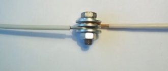
In order to check the capacitor installed in the circuit (including the so-called “electrolytes”), it is necessary to measure its capacitance. The faulty part will have to be removed from the circuit and then soldered on with a new one. Some types of capacitors do not need to be soldered, since they are attached by welding or clamps.
Does a resistor have polarity?
The author of Lithium asked a question in the Technology
: is there a difference (polarity) in how to solder resistors?! and got the best answer
Answer from Voldemar[guru] For resistors, there is no difference when desoldering. Observe polarity when soldering all active elements: transistors, diodes - their varieties: thyristors, dinistors, etc. When soldering active elements, there is a danger of their breakdown from static: this is for field-effect transistors - ground the soldering iron. Do not overheat them when soldering.
A resistor is one of the most commonly used elements in modern electronics. Its name comes from the English “resist”, which means resistance. Using a resistor, you can limit the effect of electric current and measure it, divide voltage, and set feedback in an electrical circuit. We can safely say that not a single electrical circuit or device can do without this element. That is why it is often necessary to measure the resistance of a resistor with a multimeter and check its performance. This material will tell you how to test the board for functionality with a multimeter.
Soldering boards
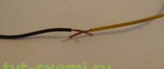
As a rule, on boards, radio components are soldered to current-carrying tracks or special “nickels”. If the tracks are already tin-plated (grey), they do not need to be tinned first.
If they are yellowish in color, they must first be coated with flux and then tinned with a soldering iron, similar to wires. After this, you can solder the parts.
Instructions on how to properly solder parts to the board:
- Using tweezers, bend the leads onto the parts so that they lie flat against the tracks (nickels) or fit into the mounting grooves.
- Fix the part evenly using tweezers.
- Treat the soldering area with flux.
- Take a small amount of solder onto the tip and apply it to the soldering point.
- Wait until the solder is evenly distributed. Do not hold the soldering iron for too long; overheating may cause the part to fail. To prevent the part from moving out of place, it should be held with tweezers.
- After cooling, wash the soldering area to remove flux residues. To do this, it is optimal to use alcohol (ethyl or isopropyl) or Galosh gasoline.
If necessary, the contacts can be coated with protective varnish for circuit boards. This is necessary to protect against wet conditions and prevent the risk of shorting when coming into contact with other surfaces.
What is a resistor
In Russian scientific literature, electrical resistors are often called simply “resistance.” From this name, its purpose immediately becomes clear - to resist the action of electric current. A resistor is a passive electrical element, since under its action the current only decreases, in contrast to active elements, which increase its effect.
From Ohm's law and Kirchhoff's second law it follows that if current flows through a resistor, then its voltage drops. Its value is equal to the strength of the flowing current multiplied by the resistance of the resistor.
Important! The symbol for a resistor in schematics is a rectangle, so it's easy to remember. Depending on the type of resistor, it is depicted as a rectangle with a symbol inside.
Resistors are divided according to installation method. They are:
- Output, that is, they are mounted through a microcircuit with radial or axial pins. This type was commonly used decades ago and is now used for simple devices;
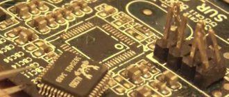
- SMD, that is, electrical resistors without leads. They have only slightly protruding legs, so they are mounted into the board itself. In modern devices they are most often used, since with automatic board assembly by a conveyor it is profitable and fast.
Hand soldering of miniature SMD elements | Homemade catalog
Surface-mount components, as their name suggests, involve mounting onto the surface of the board rather than into holes like older components. SMDs (surface mount elements) are lighter, cheaper, smaller, and can be placed closer together. These factors, as well as others, have contributed to the widespread use of leadless components today.
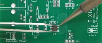
There are many relatively inexpensive tools and simple methods for soldering and desoldering SMDs.
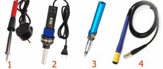
SMD Soldering Tools
- Temperature-adjustable soldering iron. A 10 bucks tool with no temperature control is not really the best tool to learn how to solder SMT. You don't need an expensive soldering station, but you do need to be able to control the temperature.
What is a multimeter
A multimeter is a device that can measure AC or DC current, voltage and resistance. It replaces three analog or digital instruments at once: ammeter, voltmeter and ohmmeter. It is also capable of changing the main indicators of any electrical network and ringing it. There are two types of multimeters: digital and analog. The first are portable devices with a display to display the results. Most multimeters on the market today are digital. The second type is already outdated and is no longer popular. It looks like a regular measuring instrument with a graduation scale and an analog needle showing the measurement value.
HOW TO PREPARE A SOLDERING IRON CORRECTLY
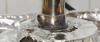
Before soldering, you should properly prepare your soldering iron. Its tip should be evenly covered with solder. Let's look at the photo:
| This is what a “dirty” sting looks like. It is very difficult to solder correctly with such soldering irons. |
| From a cold soldering iron, use a file to remove all the dirt down to pure copper (the material of the soldering iron tip is copper). |
| It should look like this. |
| We heat the soldering iron, sequentially touching the rosin and solder (several times) to achieve uniform coverage of the working part of the soldering iron with solder. |
| The result, having achieved which you can solder. |
Resistor ringing
The resistor can and should be called. You can ring without unsoldering the element from the board. Ringing an element for a break is done as follows:
- Turn on the multimeter and turn off the device if dialing is carried out without soldering;
- Using a multimeter without taking into account polarity, touch the terminals of the electrical resistor;
- Record the value. If it is equal to one, then this indicates a malfunction and a break has occurred, and the element itself should be replaced.
When not soldering, you should take into account the fact that if the circuit is complex, then you may have to make connections through bypasses and circuits. It is possible to say that an element is 100% faulty only when at least one of its legs is soldered off.
How to unsolder a part from a board
In fact, soldering in most cases involves not only connecting contacts, but also separating them. If we need to disconnect the soldered wires, then we heat up the soldering area and everything is ready. However, with radio components everything is more complicated. It’s okay if it’s a resistor or transistor when there are 2-3 pins. In this case, after a break, we quickly warm up the contacts, and then remove the part from the board. You can use small pliers or tweezers to avoid burning your hands. But with microcircuits everything is much more complicated. Often their dismantling happens unilaterally, that is, when the legs are simply cut off while still on the board, and then soldered off one at a time. This is justified in the case when the microcircuit will no longer be used. If you need to save a radio component with a large number of pins, then there are two ways. The first is to use a syringe needle. Each time you heat up the solder, you should position the needle on the leg in such a way that it separates the solder from the contact. After this procedure has been completed with all contacts of the radio component, it can be removed from the board. The second option is when solder suction is used.
In this case, a structure that looks like a syringe is attached to the heated solder. After pressing the button, it sharply raises the piston, a discharge occurs and excess solder enters the suction container. That's all the secrets of how you can desolder a part from a board.
Resistor polarity
Many people are interested in how to find out the polarity of a resistor in order to determine exactly which output contact and where to insert it. In order not to mislead people, we can immediately say that the electric resistor does not and cannot have polarity. This radio element is non-polar. It is believed that resistors are non-polar and can be connected to a printed circuit board in any position of their terminals, in any combination. As with a fuse, you can check the functionality of the resistor in any combination of multimeter contacts and leads, and the order in which it is soldered to the electrical circuits does not matter. It is only important to take into account and check the nominal resistance of the element before soldering, since then in case of malfunctions it will be more difficult to do this due to the influence on the measurement of other elements and circuits of the board.
Soldering electrical components on a universal board
So, enough theory, let's move on to practice. Select the appropriate universal circuit board. It is made of fiberglass and has many holes drilled into it. This printed circuit board is double-sided, which means that we can solder elements to it on both sides. In single-sided universal boards, we solder components only on one side; on the side of the soldering points, there are silver rings around the holes.
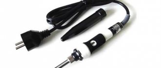
The soldering iron should be connected to a power source (USB, station or 220 V network) and placed in a safe place, the tip should be in the air so as not to melt anything and not get burned by accidentally touching it (you will get burned anyway, more than once).
Soldering iron on a plate
The tip warms up for some time. For now, insert the legs of the soldered element through the corresponding holes in the printed circuit board. Also prepare rosin.
The resistor legs are threaded through the holes in the universal board
Now bring the soldering iron tip closer to the board and the soldered leg.
Using a soldering iron to heat resistor legs being soldered
Then touch the tip to the part. Do this quickly, as if you hold the tip too long, too much stuff will melt. The entire process of soldering one solder should take 2 to 3 seconds.
Solder the resistor leg by simultaneously applying a hot soldering iron tip and tin
We will remove the tin so that excess does not remain at the soldering site
Solder the second leg of the resistor to the board
Correct (left) and incorrect (right) soldering:
The resistor legs are soldered to the board: left - right; correct - incorrect (too much solder)
a) correct; b) incorrect (too much tin, solder looks like a ball); c) wrong (too little)
Use pliers to cut off the legs of soldered components that are too long.
Cutting with pliers near the end of a resistor leg that is too long
Soldered resistor with cut lead (left side); long lead (right)
Nominal resistance
The main parameter of any resistor is the resistance value. The uniformity of this resistance is the unit of measurement Ohm. The nominal value of any purchased resistor is marked on itself, that is, on its body using markings in the form of stripes of different colors. This was done primarily for the convenience of conveyor assembly, where machines with machine vision can easily identify the element that needs to be used.
Important! You can find out the denomination in several ways: using special reference books and designation tables, as well as any measuring device.
The tables are presented in any reference book on electronics and electrical engineering, and are also included with the purchased set of resistors. The second method of determination is more convenient and understandable, since all you need to do is measure the resistance yourself. This will help determine how much the resistance differs from the nominal value and give a characteristic of the element.
Blog about electronics
| My favorite solder. |
| Thin wire for precision soldering. |
And so you decided to plunge headlong into electronics, stocked up on a soldering iron, bought solder and... What next? If worst comes to worst, everyone knows how to solder, but not many people know the subtleties of the technology and come with experience. Well, I’ll speed up this disastrous process and tell you a couple of tricks.
So, you’ve probably already read about a good soldering iron for small-scale installation, so we’ll start dancing from there. In addition to a soldering iron, you will need solder and flux. Read more about them.
Solder. This is a special alloy that melts at a temperature of about 200 degrees. The most common is 60/40 Alloy, also known as POS-61. An alloy containing 60% tin and 40% lead. Its melting point is 183-230 degrees. Typically sold as wire wound on spools. For small installations, it is better to take one with a smaller wire diameter - it is easier to dose. I have two coils, one with 0.3 mm solder wire, the second 0.6 mm. Well, I also have one and a half millimeter, but I hardly use it. Only if I massively solder massive parts that require a lot of solder. It’s better to buy imported solder; unfortunately, the Russian product pretty much sucks. There may be high-quality ones, but usually I came across low-grade slag. A coil of solder, as in the picture, should cost from 150-200 rubles, more expensive is possible, cheaper is not advisable. It’s better to spend money once, but then have beautiful and high-quality soldering and not worry about it. A reel usually lasts for a year and a half or two, which is at least. It’s also useful to buy yourself some Rose alloy. This is also a kind of solder, but its melting point is completely ridiculous - somewhere around 90-100 degrees. This alloy is sometimes useful for dismantling, but this will be discussed in a separate article later.
| Rosin - a classic of the genre |
The simplest and most popular flux. This is ordinary purified pine resin. When soldering, first take a little solder onto the tip, then poke it into the rosin to get resin onto the tip, and then quickly solder before the resin evaporates. The method is not very convenient, so they often do it differently. Take ordinary ethyl (medicinal) alcohol and dissolve crushed rosin in it until it dissolves. Afterwards, this solution is applied with a brush to the parts to be soldered and soldered. The activity of rosin is not high, so sometimes nothing works out - the details are not tinned, but rosin has one huge advantage, which sometimes overcomes all its shortcomings. Rosin is absolutely passive. That is, it does not need to be removed from the soldering site, since it does not oxidize or reduce metals, while being an excellent dielectric. This is why I try to make the most critical solderings with alcohol-rosin flux.
| LTI-120 |
| Glycerol-hydrazine |
| Rosin-gel. Super thing |
| F-34A - chemical weapon of mass destruction. |
| Flux palette |