5. WEAR AND DURABILITY OF CUTTING TOOLS
Dullness of cutting tools is caused by ductile fracture, brittle fracture (chipping), and frictional wear.
Plastic deformation of the metal of the cutting part occurs in tools made of steel, which retains high toughness and ductility in the hardened state. Each pair of processed and tool materials corresponds to a region of cutting modes within which plastic deformation of the tool occurs.
When turning medium-hard steel with a cut layer thickness of 0.3 mm, cutters made of carbon tool steel lose their functionality at cutting speeds above 0.25–0.35 m/s; from high-speed - 1.35–2 m/s; from hard alloy - 10–17 m/s.
Brittle destruction of the cutting part of the tool occurs when the thickness of the cut layer exceeds the limit value characteristic of a given pair of processed and tool materials and the shape of the tool.
The type of fracture (ductile or brittle) depends on the properties of the tool material and the method of loading the tool. If the tensile strength is less than the shear strength, then brittle fracture occurs. Otherwise, ductile fracture occurs. Mineral-ceramic materials have poor tensile strength and break brittlely. Tool steel and hard alloys, depending on loading conditions, undergo destruction either by separation (brittle) or shear (ductile).
Wear due to friction is typical for all tools without exception. There are abrasive, adhesive, chemical, and diffusion wear.
Abrasive wear usually predominates when machining cast iron, even at low cutting speeds, especially when stripping along a casting skin containing particles of free cementite and inclusions of molding material.
The same type of wear is observed during intermittent cutting (planing, milling), when the temperature is lower than during continuous turning. Abrasive wear of tools when processing steel increases with increasing content of carbon and carbide-forming alloying elements.
Adhesive wear most often occurs when machining steel with carbide tools at speeds that cause temperatures below 500 °C. Adhesive wear of high-speed steel is less intense than that of a hard alloy due to lower brittleness and higher cyclic strength.
Chemical wear is critical when cutting steel, molybdenum and other materials with high speed steel tools in the presence of chemicals.
At temperatures above 500–600 °C, mutual diffusion of workpiece and tool materials is observed. As a result, structural transformations occur in the surface layers of the tool, as a result of which its hardness and strength decrease [41]. This leads to diffusion wear.
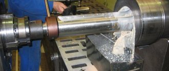
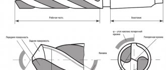
Wear occurs on both the front and rear surfaces of the tool (Fig. III.17). Intensive wear of the rake surface is typical for roughing steel without cooling with tools sensitive to high temperatures, with a large thickness of the cut layer ( a
≥ 0.5 mm). The depth of the hole reaches 0.6–0.8 mm or more.
The back surface of the cutters wears out mainly when processing cast iron, turning steel with cooling and low feed, when processing steel with wear-resistant hard alloys, and also when peeling castings. Wear on the flank surface predominates during such types of processing as milling, broaching, threading, and teeth.
The degree of dullness can be judged by the highest height of the wear area, which is usually observed directly at the tip of the tool. When peeling a casting along the skin, the greatest wear is observed at the point of contact of the cutting edge with the outer surface of the casting skin.
When cutting a layer 0.10...0.15 mm thick with a low or average cutting speed for a given tool material, wear occurs simultaneously along the rear and front surfaces. Such wear is typical for finishing cutters made of high-speed steel when working with cooling cutters equipped with a hard alloy, face and disk mills, drills, and countersinks.
In table III.4–III.8 show the permissible wear values for the most commonly used tools.
During finishing processing, the permissible wear is determined by the required processing accuracy or the roughness of the machined surface and should be significantly less than during roughing. Durability period T
is determined by the operating time of the cutting tool to the accepted value of dullness.
Total tool life
ι). (III.18)
where ι is the number of sharpenings the tool can withstand.
Number of regrinds (Fig. III.18), where is the total permissible amount of grinding (Table III.9); — calculated amount of grinding; here is the minimum required amount of grinding; — additional amount of grinding, the values of which for various tools are given below:
Tool Δ, mm
Incisors…………………………………………………………………………………. 0.1–0.25
Drills………………………………………………………………………………… 0.2–0.3
Countersinks………………………………………………………. 0.1–0.2
Reams……………………………………………………….. 0.2–0.3
Milling cutters………………………………………………………………………………… 0.1–0.2
Taps, dies, thread-cutting round dies…………. 0.05–0.1
Dental cutting incisors…………………………………………… 0.05–0.15
Dolbyaki……………………………………………………………. 0.1
Broaches……………………………………………………….. 0.05
When worn along the flank surface, where a
- rear angle along the front surface.
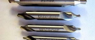
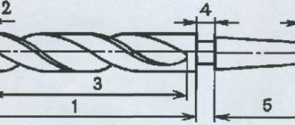
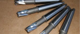
Twist drills Technical specifications
Twist drills.
Specifications MKS 73.060.99 OKP 39 1202
GOST
2034-80
Date of introduction 01/01/82
This standard applies to drills made of high-speed steel with a diameter of 0.25 to 80.0 mm, for drilling holes in structural steels of increased and high machinability with a hardness of 159...229 HB, carbon and alloy structural steels with a hardness of 179...321 HB, carbon and alloy tool steels steels with hardness 179...269 HB, gray and malleable cast iron with hardness 170...210 HB, manufactured for the needs of the national economy and for export.
The requirements of this standard regarding section. 1, 3, 4, 5, pp. 2.2 and 2.3 are mandatory, other requirements are recommended.
(Changed edition, Amendment No. 2, 3).
RUSSIAN DRILLS, GOST DRILLS
The A2TK.RU company sells metal-cutting tools, stainless steel fasteners and rigging. If you or your company are engaged in construction or finishing work, or you are facing home renovations (apartment renovations), you can always buy tools and fasteners from us at very low prices. We offer a very wide range of metal drills. Cheap prices for drills, a variety of types of metal drills, various drill coatings and, of course, delivery of drills in any quantity and to any point in the Russian Federation. You can buy a drill in our online store A2TK.RU or in retail stores for cash or by bank transfer. We work with both companies and ordinary customers who need to attach a shelf, hang a clock or drill a hole in any material, we sell drills individually and drills wholesale. From us you will purchase Russian drills manufactured by the best companies and firms that comply with GOSTs and standards. We have been working for more than five years, only with trusted manufacturers who, during the manufacture of drills at all stages of production, control quality indicators in measuring laboratories for:
a) compliance of metal and alloys (content of alloying elements); b) the ratio of the drill shape to typical standard parameters; c) the quality of additional processing and the thickness of the additional coating of the drill; d) the symmetry of all elements of the drill and the quality of its sharpening. Our professional consultants will always help you, advise you and offer to buy a drill that is suitable for solving your specific technical problem and strictly complies with one of the GOST standards: 1. GOST 10902-77; 2. GOST 10903-77; 3. GOST 886-77; 4. GOST 12121-77. Our company sells only high-quality drills; they will never let you down in work of any complexity.
TECHNICAL REQUIREMENTS
1.1. Drills must be manufactured in three accuracy classes:
A1 - increased accuracy;
B1, B - normal accuracy.
Drills of accuracy class A1 are intended for drilling holes of 10-13 accuracy grades, accuracy class B1 - for drilling holes up to 14 accuracy grade, accuracy class B - for drilling holes up to 15 accuracy grade.
(Changed edition, Amendment No. 2).
1.2. Drills must be made of high-speed steel in accordance with GOST 19265. It is allowed to manufacture drills from high-speed steel of other grades, ensuring the durability of drills is not inferior to the durability of drills made of high-speed steel in accordance with GOST 19265.
At the customer's request, it is possible to manufacture drills from alloy steel grade 9ХС in accordance with GOST 5950.
(Changed edition, Amendment No. 1).
1.3. The following are not allowed in the welding zone: lack of penetration, ring cracks and surface holes.
(Changed edition, Amendment No. 3).
1.4. The shanks of welded drills must be made of steel grade 45 according to GOST 1050 or grade 40X according to GOST 4543.
1.5. The hardness of the working part of the drills should be:
for high-speed steel drills:
63.. .65 HRC3……………………………. diameter up to 5 mm
63.. .66 HRC3……………………………. » St. 5 mm
for drills made of steel grade 9ХС:
62.. .64 HRC3……………………………. diameter up to 5 mm
62.. .65 HRC3……………………………. » St. 5 mm
The hardness of the working part of drills made of high-speed steel with a vanadium content of at least 3% and cobalt of at least 5% should be higher by 1-2 HRC3 units.
Official publication Reproduction prohibited
★
For solid drills, hardness must be ensured at a length of the groove reduced by no more than 1.5 drill diameters; for welded drills, at a length of at least 2/3 of the length of the helical groove.
Note: Drills with a diameter of up to 3 mm can be subjected to heat treatment along the entire length of the drill.
(Changed edition, Amendment No. 1, 3).
1.6. The hardness of the drill bits with a conical shank should be 32…47 HRC3.
1.7. The hardness of drill bits with a cylindrical shank must be at least 27 HRC3.
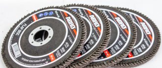
DRILL COATING
Drill bits may vary in color. The color of the drill bit can indicate what it is made of or what kind of coating or additional treatment was used. The most common ones are steel-colored drills; they are simplified in their technical parameters (thermal and mechanical resistance) and do not have a high price level. Drills containing titanium and cobalt have excellent performance. They are five times more durable than regular ones, hold the factory sharpening perfectly, and have bright gold and gold colors, respectively. Drills coated with titanium nitride - TiN or TiALN - titanium aluminum nitride are very common. To carry out the drilling process at home or work with small volumes, black drills are usually used. A black drill is the result of treating the tool with superheated steam, which also allows you to improve the parameters of the drill; such drills correspond to: price - quality.
1.9. 1.10. (Excluded, Amendment No. 3).
1.11. The roughness parameters of drill surfaces according to GOST 2789 should not be more than those indicated in the table. 1.
Table 1
µm
| Standards for roughness parameters | ||||||
| Drill surface name | Ra | Rz | Ra | Rz | Ra | Rz |
| Drill accuracy class | ||||||
| A1 | IN 1 | IN | ||||
| Rear surfaces of the cutting part | 3,2 | 6,3 | 6,3 | |||
| Surfaces of guide strips Surfaces of grooves of drills with diameter: | — | 3,2 | — | 3,2 | — | 6,3 |
| up to 1.0 mm | — | 3,2 | — | 10 | — | 10 |
| St. 1.0 mm | — | 6,3 | — | 10 | — | 10 |
| Shank surfaces | 0,8 | — | 1,25 | — | 1,6 | — |
Note. For precision class B drills with milled grooves, groove roughness Rz< 20 µm is allowed.
1.12. The tolerance fields for the diameters of the cutting part of the drills, measured at the beginning of the working part, should be:
b8 - for drills of accuracy classes A1 and B1;
b9 - for drills of accuracy classes B.
III.6. Allowable wear of the cutting part of the cutters
| Milling cutters | Cutting part material | Processed material | Flank wear, h h, mm, during processing | ||
| rough | finishing | ||||
| Face | Hard alloy | Steel | 1,0–1,2 | ||
| 1,5–2,0 | 0,3–0,5 | ||||
| High speed steel | |||||
| Disk | Hard alloy | Cast iron | 1,5–2,0 | ||
| High speed steel | Steel | 1,0–1,2 | |||
| Cast iron | 0,4–0,6 | 0,15–0,25 | |||
| Cylindrical | Hard alloy | Steel | 0,5–0,6 | ||
| 0,4–0,6 | 0,15–0,25 | ||||
| High speed steel | |||||
| Hard alloy | Cast iron | 0,7–0,8 | |||
| High speed steel | 0,5–0,8 | 0,2–0,3 | |||
| Slotted and cut-off | High speed steel | Steel and cast iron | 0,15–0,2 | ||
| End | Hard alloy | Steel | 0,2–0,3* | 0,3–0,5** | |
| High speed steel | 0,2–0,5 | ||||
| Profile unbacked backed | all materials | Steel and Cast iron | 0,6–0,7 0,3–0,4 | 0,2–0,3 0,2 | |
* Mills with crowns.
**Cutters with soldered plates.
1.11, 1.12. (Changed edition, Amendment No. 2).
1.13. Maximum deviations of drill lengths should not be more than:
2j s 16 - for total length;
3j s 16 - for the length of the working part.
1.14. Drills must have a reduction in diameter on the working part towards the shank (reverse taper) within 0.02-0.08 mm per 100 mm of length.
Notes:
1. Drills with a diameter of up to 1 mm can be manufactured without reducing the diameter (increasing the diameter towards the shank is not allowed).
2. For drills with a diameter of up to 3 mm, it is allowed to reduce the diameter towards the shank to 0.1 mm.
3. For drills with a cylindrical shank with a diameter of up to 12 mm, a reduction in diameter along the entire length of the drill is allowed.
1.15. For drills of accuracy class A1, the symmetry tolerance of the core in radius terms relative to the axis of the working part of the drill must correspond to that specified in table. 3.
Table 3*
mm
| Drill diameter | Symmetry tolerance | Drill diameter | Symmetry tolerance |
| Up to 1 | 0,03 | St. 6 to 10 | 0,08 |
| St. 1 to 3 | 0,04 | » 10 » 20 | 0,10 |
| » 3 » 6 | 0,05 | » 20 » 30 | 0,15 |
III.10. Recommended service life periods TM, min, for multi-tool setups of lathes
| Settings group | Characteristics of the group | Number of tools in setup, pcs. | ||||||
| 3 | 5 | 8 | 10 | 15 | 20 | St. 20 | ||
| Settings with even loading of tools | The diameters of the surfaces to be turned differ by no more than 1–2 times; the number of chamfering and scoring cutters is no more than 20% of the total number of setting tools | 150 | 200 | 300 | 350 | 400 | – | – |
| Settings are average for uniform loading of tools | All adjustments not related to groups 1 and 3 | 100 | 120 | 150 | 180 | 230 | 260 | 300 |
| Setups with big differences in tool loading | The diameters of the surfaces to be turned differ by more than 2 times; the number of chamfering and other low-load tools is over 50% of the total number of tools | 70 | 90 | 110 | 130 | 150 | 170 | 180 |
1.14, 1.15. (Changed edition, Amendment No. 2).
1.16. The symmetry tolerance of the driver of drills with a cylindrical shank in radius terms relative to the axis of the shank must correspond to drills with a diameter, mm:
From 3.00 to 4.75 ………………………….. 0.050
St. 4.75 to 9.50………………………….. 0.060
St. 9.50 to 15.00…………………………. 0.075
St. 15.00 to 40.00 ………………………… 0.090
(Changed edition, Amendment No. 3).
1.17. The straightness tolerance of the main cutting edges for drills of accuracy class A1 must correspond to that indicated in table. 4.
Table 4
mm
| Drill diameter | St. 1 to 3 | St. 3 to 6 | St. 6 to 10 | St. 10 to 20 | St. 20 to 30 |
| Straightness tolerance | 0,06 | 0,08 | 0,10 | 0,15 | 0,20 |
III.8. Allowable wear of the cutting part of thread-cutting tools
| Tool | Type of processing | Flank wear h h, mm | ||
| Threaded cutters and dies | Draft | 0,8–1,7 | ||
| Finishing | 0,3–0,4 | |||
| Thread cutters, group | Treatment become | s ≤ 1.25 | 0,1–0,2 | |
| s ≤ 1.75 | 0,2–0,3 | |||
| s > 1.75 | 0,3–0,6 | |||
| Machining malleable cast iron | s ≤ 1.25 | 0,15–0,25 | ||
| s ≤ 1.75 | 0,25–0,4 | |||
| s > 1.75 | 0,4–0,8 | |||
| Dies | round | Steel processing | 0,1d 0,5 | |
| tangential | On bolt cutting machines | 0,8–2,0 | ||
| machine | Steel processing | 0,125d | ||
| Cast iron processing | 0,07d | |||
| automatic nuts | Nut processing | hot rolled | 0,125d | |
| cold-formed and hot-rolled, pickled, drilled | 0,5d | |||
| Cutters with carbide inserts | Draft | 0,8–1,0 | ||
| Finishing | 0,3–0,4 | |||
| Cutters with carbide inserts for rotating heads | Machining imprecise threads and preliminary | 0,8–0,1 | ||
| Precision thread processing one pass | 0,3–0,4 | |||
The required amount of tool is determined by the formula
,
where is the main technological time for processing one workpiece, min; n
— estimated number of workpieces, pcs.; — random attrition coefficient equal to 1.05–1.3.
The dependence of the service life period on the cutting speed is extreme. In many cases, the applied cutting conditions correspond to the descending branch of the curve, for which the formulas are valid
; (III.19)
, (III.20)
where T
— durability period, min;
C
is the proportionality coefficient, which depends on the cutting conditions;
z
is an indicator of relative speed, depending on the type of processing and tool material;
m = 1/ z
is an indicator of relative resistance (see Chapter VIII).
ACCEPTANCE RULES
2.1. Acceptance rules - according to GOST 23726.
2.2. Testing of drills for the average durability period is carried out once every three years, for the 95% durability period once a year, on at least 5 drills.
2.3. Drills of accuracy classes A1 and B (or B1) of the same standard size from each range of diameters, mm: from 0.25 to 3.0 must be tested; St. 3.0 to 11.0; St. 11.0 to 18.0; St. 18.0 to 23.0; St. 23.0 to 80.0.
2.2; 2.3. (Changed edition, Amendment No. 3).