Strength limits of materials
Quick search
A certain threshold value for a specific material, exceeding which will lead to the destruction of the object under the influence of mechanical stress. The main types of strength limits: static, dynamic, compressive and tensile. For example, the tensile strength is the limit value of a constant (static limit) or variable (dynamic limit) mechanical stress, exceeding which will rupture (or unacceptably deform) the product. Unit of measurement - Pascal, N/mm² = .
Yield strength (σt)
The amount of mechanical stress at which the deformation continues to increase without increasing the load; used for calculating permissible stresses in plastic materials.
After passing the yield point, irreversible changes are observed in the metal structure: the crystal lattice is rearranged, and significant plastic deformations appear. At the same time, self-strengthening of the metal occurs and after the yield point, the deformation increases with increasing tensile force.
This parameter is often defined as “the stress at which plastic deformation begins to develop,” thus identifying the limits of yield and elasticity. However, it should be understood that these are two different parameters. The yield strength values exceed the elastic limit by approximately 5%.
Endurance limit or fatigue limit (σR)
The ability of a material to withstand loads that cause cyclic stress. This strength parameter is defined as the maximum stress in a cycle at which fatigue failure of the product does not occur after an indefinitely large number of cyclic loads (the basic number of cycles for steel is Nb = 10 7). The coefficient R (σR) is taken to be equal to the cycle asymmetry coefficient. Therefore, the fatigue limit of the material in the case of symmetric loading cycles is designated as σ-1, and in the case of pulsating ones - as σ0.
Note that fatigue tests of products are very long and labor-intensive; they involve the analysis of large volumes of experimental data with an arbitrary number of cycles and a significant scatter of values. Therefore, special empirical formulas are most often used that connect the endurance limit with other strength parameters of the material. The most convenient parameter is considered to be the tensile strength.
For steels, the bending endurance limit is usually half the tensile strength: For high-strength steels, you can take:
For ordinary steels during torsion under conditions of cyclically changing stresses, the following can be accepted:
The above ratios should be used with caution, because they were obtained under specific loading conditions, i.e. during bending and torsion. However, when testing in tension-compression, the endurance limit becomes approximately 10-20% less than in bending.
Proportional limit (σ)
The maximum stress value for a particular material at which Hooke’s law still applies, i.e. body deformation is directly proportional to the applied load (force)
Please note that for many materials, reaching (but not exceeding!) the elastic limit leads to reversible (elastic) deformations, which, however, are no longer directly proportional to stress. Moreover, such deformations may “lag” somewhat behind the increase or decrease in load
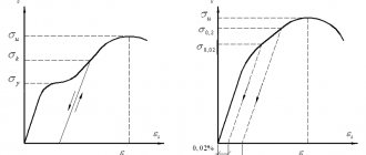
Diagram of the deformation of a metal sample under tension in the coordinates elongation (Є) - stress (σ).
1: Absolute elasticity limit.
2: Limit of proportionality.
3: Elastic limit.
4: Yield strength. (σ 0.2)
www.smalley.ru
Basic definition
During use, any structure experiences different loads in the form of compression, tension or impact. They can act both separately and together.
Modern designers strive to reduce the mass of steel parts to save material, but at the same time prevent a critical reduction in the load-bearing capacity of the entire structure. This happens by reducing the cross-section of steel reinforcement.
Depending on the purpose of the objects, some requirements for steel may change, but there is a list of standard and important indicators. Their values are calculated at the stage of designing parts and assemblies of the future structure. The workpiece must have high strength with appropriate ductility.
First of all, when calculating the strength of a steel product, attention is paid to the yield strength . This value characterizes the behavior of parts when exposed to influences.
The yield strength of a material is the value of the critical stress at which the material continues to deform independently without increasing the load. This characteristic is measured in Pascals and allows you to calculate the maximum possible stress for ductile steel.
After passing this limit, irreversible processes of distortion of the crystal lattice occur in the material. With a subsequent increase in the force on the workpiece and overcoming the yield point, the deformation increases.
The yield stress is sometimes confused with the elastic limit . These are similar concepts, but the elastic limit is the value of the maximum resistance of the metal and it is slightly lower than the yield strength.
The yield value is approximately five percent higher than the elastic limit.
Popular types of concrete
There are ordinary or heavy concrete (M25-M800) and light concrete (M10-M200). Let's take a closer look at them.
Lungs
From M5 to M35 are used for non-load-bearing structures - they are not particularly strong. M50 and M75 are suitable for preparatory work before pouring concrete. M100-M150 – for low-rise construction, structures, lintels.
M200-M300 are used for most construction tasks. M200 corresponds to class B15, its strength is 196 kgf/m2 or 15 MPa. M250 (B20) has an average strength of 262 kgf/cm2 or can withstand a pressure of 20 MPa, like the above brand, it gains 70% of its strength after 28 days, and the remaining 30% within six months. These are lightweight concretes. Screeds, floors, blind areas, foundations, stairs, supports, curbs are most often made from it. It freezes at sub-zero temperatures and loses up to 5% of its resistance when defrosted.
Lightweight concrete can be checked by hitting it with a hammer or rubbing it with a sharp object - quite distinct marks will remain on the surface.
Regular
M350 (class B25) - a cubic meter of this concrete can withstand a load of 25 MPa, it corresponds to M250. M400 (class B30) - withstands a load of 30 MPa. These grades and higher are used for multi-storey buildings, load-bearing, monolithic structures, swimming pool bowls. Most often used for road surfaces and floor slabs, as it is waterproof (class W8), frost-resistant (F200).
Grades from M350 (classes from B25) and more relate to more durable concrete, they have a high density and better resistance to frost and humidity, but are much heavier.
Tensile strength
— mechanical stress σ B > , above which material destruction occurs. In other words, this is a threshold value, exceeding which mechanical stress will destroy a certain body made of a specific material. It is necessary to distinguish between static and dynamic strength limits. There is also a distinction between compressive and tensile strength limits.
Viscosity of steels
An important mechanical property of steel is its toughness. Typically, the term toughness is used as a measure of the ability of a metal to break down non-brittlely.
The nature of fracture - brittle or ductile - can be best considered using the example of ferritic steels. All metals with a body-centered cubic atomic lattice - like ferritic steels - have one common drawback. They break down brittlely at low temperatures, while at sufficiently high temperatures they break down normally—plastically. The temperature of transition from ductile to brittle fracture is called the ductile-brittle transition temperature. It is defined as the temperature below which brittle fracture occurs. The brittle transition temperature can in principle be determined by tensile testing, but in uniaxial tension its value is significantly lower than that observed in complex steel parts. Experience has shown that impact strength tests using the Charpy method are in much better agreement with experimental data on brittle fracture of complex parts. A diagram of the Charpy impact test method is shown in Figure 4.
Figure 4 – Scheme of impact testing using the Charpy method
Mechanical properties
There are 5 characteristics:
- The tensile and tensile strength of steel is temporary resistance to external forces, stress arising internally.
- Plasticity is the ability to deform, change shape, but maintain the internal structure.
- Hardness - Willingness to meet harder material without causing significant damage.
- Impact strength is the ability to resist impacts.
- Fatigue is the duration of preservation of qualities under the influence of cyclic loads.
Compressive Strength
Compressive strength is an important mechanical property. Characterized by the rock's ultimate compressive strength in a dry state
The current standard for blocks divides rocks according to this indicator into three classes: strong (over 80 MPa), medium strength (40-80 MPa), and low-strength (5-40 MPa).
Rice. 16. Diagram of a hydraulic press for testing samples for compression
The standard for side stones (GOST 6666-81) allows the production of these products from rocks with a compressive strength not lower than MPa: for igneous rocks - 90, metamorphic and sedimentary - 60. The standard for side stones (GOST 23668-79) allows their manufacture from igneous rocks with a tensile strength of at least 100 MPa. Wall stones made of rocks (GOST 4001 - 84), depending on the compressive strength, are divided into 14 grades (from 4 to 400).
1 – bed; 2 – hydraulic cylinder; 3 – piston, 4 – lower plate; 5 – tested stone sample; c – top plate; 7 – setscrew; 8 – pressure gauges; 9 – pump
Determination of the compressive strength of rocks is carried out on five cubic samples with an edge of 40-50 mm or cylinders with a diameter and height of 40-50 mm. Before testing, each sample is cleaned with a brush from loose particles and dust and dried to a constant weight. The edges of the samples to which the load will be applied are then carefully processed on a grinding machine to ensure that they are parallel. After this, the samples are measured with a caliper, placed in the center of the press support plate (Fig. 16), which has markings for centering the samples, and pressed with the top plate of the press, which should fit tightly over the entire surface of the upper edge of the samples.
The load on the sample during testing is increased continuously and constantly at a rate that ensures its destruction 20-60 s after the start of testing. The magnitude of the breaking load must be at least 10% of the maximum force developed by the press. The moment of sample destruction is determined by the beginning of the reverse movement of the force meter pointer when the loading device is operating.
Strength classes and their designations
All categories are written down in regulatory documents - GOSTs, according to which all Russian entrepreneurs produce any rolled metal and other metal products. Here is the correspondence between the designation and parameter in the table:
| Class | Tensile strength, N/mm2 |
| 265 | 430 |
| 295 | 430 |
| 315 | 450 |
| 325 | 450 |
| 345 | 490 |
| 355 | 490 |
| 375 | 510 |
| 390 | 510 |
| 440 | 590 |
We see that for some classes the PP indicators remain the same, this is explained by the fact that, with equal values, their fluidity or relative elongation may differ. Depending on this, different maximum thickness of rolled metal is possible.
Parameter classification
The material has temporary resistance in response to impacts of various types, so the characteristic is classified into several groups. Forces to which the workpiece or structural element is subjected:
- Stretching. The product is pulled by the edges using a special machine.
- Torsion. The object is placed in conditions under which the rotating shaft operates.
- Bend. The workpiece is bent and unbent in several directions.
- Compression. The material is pressed alternately from different sides.
For the same material, the PP may vary. An example is steel. It is used more often than other alloys because steel structures have proven to be the strongest, most durable, and most resistant to the elements. At the same time, they are reliable and do not emit harmful substances into the atmosphere.
There are several grades of steel. They are produced using different technologies, and depending on this, the characteristics of the workpieces and structures differ. For conventional brands, the PP is 300 MPa. As the carbon content increases, the strength increases. The hardest grades have a value of 900 MPa. Factors on which strength characteristics depend:
- the amount of useful and undesirable impurities;
- method of heat treatment (cryotreatment, hardening, annealing).
How are the properties of metals determined?
They check not only what is called tensile strength, but also other characteristics of steel, for example, hardness. The tests are carried out as follows: a ball or cone made of diamond, the most durable rock, is pressed into the sample. The stronger the material, the smaller the mark left. Deeper, wider-diameter prints are left on soft alloys. Another experience - for a blow. The impact occurs only after a pre-made cut on the workpiece. That is, the destruction is checked for the most vulnerable area.
Classification by purpose
The classification of steel types by purpose has already been given above. Marking of structural steels includes the following designations:
- Construction - denoted by the letter C and numbers characterizing the yield strength.
- Bearing - designated by the letter Ш. Next comes the designation and content of alloying additives, mainly chromium.
- Instrumental unalloyed - denoted by the letter U and carbon content in tenths of a percent.
- High-speed - denoted by the letter P and symbols of alloying components.
- Unalloyed structural steel has the symbols Cn and a number indicating the carbon content in tenths or hundredths of a percent.
Classification of steel by purpose
The remaining varieties, including tool grades made of alloy steels, do not have special designations other than their chemical composition, so the decoding and purpose of individual types can only be determined from reference literature.
Alloying additives in alloys
These are substances deliberately added to the melt to improve the properties of the alloy and bring its parameters to the required ones. Some of them are added in large quantities (more than a percent), others in very small quantities. I most often use the following alloying additives:
- Chromium. Used to increase hardenability and hardness. Share – 0.8-0.2%.
- Bor. Improves cold brittleness and radiation resistance. Share – 0.003%.
- Titanium. Added to improve the structure of Cr-Mn alloys. Share – 0.1%.
- Molybdenum. Increases strength characteristics and corrosion resistance, reduces fragility. Share – 0.15-0.45%.
- Vanadium. Improves strength parameters and elasticity. Share – 0.1-0.3%.
- Nickel. Promotes an increase in strength characteristics and hardenability, but at the same time leads to an increase in fragility. This effect is compensated by the simultaneous addition of molybdenum.
Metallurgists also use more complex combinations of alloying additives, achieving unique combinations of physical and mechanical properties of steel. The cost of such grades is several times (or even tens of times) higher than the cost of conventional low-carbon steels. They are used for particularly critical structures and assemblies.
If you find an error, please select a piece of text and press Ctrl+Enter.
Constructing a compression strain diagram is associated with a number of difficulties.
The first of them is that when the rod is compressed, a loss of stability may occur (curvature of the axis of the rod). The problem of stability of rods will be studied in the future, but now we note that to eliminate the loss of stability it is necessary to use samples with a small ratio . However, as this ratio decreases, the influence of the friction forces arising between the supporting surfaces on the experimental results increases.
Read also: Purpose of straight cutter
In Fig. 4.4a shows samples for compression tests. The simplest way is to transmit force through flat ends. The sample must be processed accurately enough to obtain a uniform distribution of compressive stresses at the ends. To reduce the influence of friction forces, the ends are lubricated with grease (vaseline, paraffin, etc.). Another way to compensate for friction forces is to use half-length conical surfaces at the ends (Fig. 4.4, b).
To carry out successive tensile and compression tests, tubular samples are used (Fig. 4.4, c), and the force is transmitted to the sample body using threads.
Rice. 4.4. Samples of materials for compression testing
The main application of compression tests is to study the strength and deformation of brittle materials, since they are used primarily for structural elements subject to compression. Compression testing is widely used to examine building materials (concrete, brick, stone, etc.). Cubes with an edge size of 30-40 mm are usually used as samples.
For brittle materials, failure occurs at a deformation of only a few percent, and the compressive strength is of primary importance. In Fig. Table 4.5 shows two types of destruction of building materials under compression. In the nervous case (Fig. 4.5, a) (friction forces act at the ends of the sample), the destruction is associated with the action of tangential stresses. In the second case (Fig. 4.5, b) (friction forces at the ends are small), longitudinal cracks are formed, caused by tensile deformation in the transverse direction. It should be noted that for brittle materials the compressive strength is many times greater than the tensile strength.
Rice. 4.5. Destruction of brittle building materials under compression: a - the ends of the sample are not lubricated; b - ends are lubricated with paraffin
When testing plastic materials for compression, the cross sections increase (“flattening”) of the sample (Fig. 4.6). The yield strength is clearly defined, which for most plastic structural materials turns out to be the same as in tension. The latter is explained by the fact that those responsible for the appearance of plastic deformations are tangential stresses, which under the action of tensile and compressive forces differ only in sign.
Rice. 4.6. Flattening of plastic materials during compression
The ultimate compressive strength of plastic materials under uniaxial compression is not detected. With all-round compression, materials withstand very high pressures, and usually brittle materials (marble, etc.) become plastic.
It can be assumed that plastic materials can withstand very high compressive stresses, and destruction can occur as a result of the presence of tangential stresses in inclined areas.
Alloy check
Before launching into production, tests are carried out to study the properties of the metal alloy. Metal samples are subjected to various loads until all properties are completely lost.
- Statistical load.
- Testing the endurance and fatigue of steel.
- Stretching an element.
- Bend and torsion testing.
- Combined bending and tensile endurance.
For these purposes, special machines are used and conditions are created that are as close as possible to the operating mode of the future structure.
Testing
To carry out tests on a cylindrical sample with a cross-section of twenty millimeters and a calculated length of ten millimeters, a tensile load is applied. The sample itself has a length of more than ten millimeters so that it can be securely grasped, and a length of ten millimeters is marked on it and this is what is called the calculated length. The tensile force is increased and the increasing elongation of the sample is measured. For clarity, the data is plotted on a graph. It is called a conditional stretch diagram.
Read also: How to use a screwdriver with a battery indicator
With a small load, the sample elongates proportionally . When the tensile force increases sufficiently, the limit of proportionality will be reached. After passing this limit, disproportionate elongation of the material begins with a uniform change in the tensile force. Then a limit is reached, after which the sample cannot return to its original length. When passing this value, the test part changes without increasing the tensile force. For example, for steel rod Art. 3 this value is equal to 2450 kg per square centimeter.
Unexpressed flow point
If, under constant force, a material is capable of deforming on its own for a long time, then it is called ideally plastic.
During testing, it often happens that the yield point is not clearly defined, then the definition of the conditional yield strength is introduced. This means that the force acting on the metal caused a deformation or permanent change of about 0.2%. The value of the residual change depends on the ductility of the metal.
The more ductile the metal, the higher the residual deformation value. Typical alloys in which such deformation is not clearly expressed are copper, brass, aluminum, and steels with low carbon content. Samples of these alloys are called densified.
When a metal begins to “flow,” as experiments and research demonstrate, strong changes occur in its crystal lattice. Shear lines appear on its surface and the layers of crystals shift significantly.
After the metal spontaneously stretches, it passes into the next state and again acquires the ability to resist. Then the alloy reaches its strength limit and the weakest area clearly appears on the part, where a sharp narrowing of the sample occurs.
The cross-sectional area becomes smaller and this is where rupture and destruction occur. The magnitude of the tensile force at this moment drops along with the value of stress and the part breaks.
High-strength alloys can withstand loads of up to 17,500 kilograms per square centimeter. The tensile strength of ST.3 steel is in the range of 4–5 thousand kilograms per square centimeter.
Plasticity characteristic
The ductility of a material is an important parameter that must be taken into account when designing structures. Plasticity is determined by two indicators:
- residual elongation;
- narrowing upon rupture.
Permanent elongation is calculated by measuring the total length of the part after it has broken. It consists of the sum of the lengths of each half of the sample. Then the ratio to the original conditional length is determined as a percentage. The stronger the metal alloy, the lower the elongation value.
Residual narrowing is the percentage ratio of the narrowest point of the rupture to the original cross-sectional area of the rod under study.
Fragility index
The most brittle metal alloys are considered to be tool steel and cast iron. Fragility is the inverse property of plasticity, and it is somewhat conditional, since it strongly depends on external conditions.
Such conditions may be:
- Ambient temperature. The lower the temperature, the more fragile the product becomes.
- The rate of change of applied force.
- Ambient humidity and other parameters.
When external conditions change, the same material behaves differently. If a cast iron bar is clamped on all sides, it will not break even under significant loads. And, for example, when there are grooves on a steel rod, the part becomes very fragile.
Therefore, in practice, it is not the concept of the brittleness limit that is used, but the state of the sample is determined as brittle or rather ductile.
Material strength
This is a mechanical property of the workpiece and is characterized by its ability to withstand loads without completely collapsing. For the test sample, conditions are created that best reflect future operating conditions and a variety of influences are applied, gradually increasing the load. An increase in impact forces causes plastic deformations in the sample. In plastic materials, deformation occurs in one, pronounced area called the neck. Brittle materials can fail in several areas at the same time.
Steel is tested to accurately determine various properties in order to obtain an answer about the possibility of its use in certain conditions during construction and the creation of complex structures.
The fluidity values of various steel grades are included in special Standards and Specifications. There are four main classes. The fluidity value of products of the first class can reach up to 500 kg/cm2, the second class meets the load requirements of up to 3 thousand kg/cm2, the third - up to 4 thousand kg/cm2. and the fourth class can withstand up to 6 thousand kg/cm2.
Tensile strength
- this is the same as the temporary resistance of the material.
But despite the fact that it is more correct to use the term temporary resistance
, the concept of tensile strength has taken root better in technical colloquial speech. At the same time, in regulatory documentation and standards the term “temporary resistance” is used.
Strength
- this is the resistance of a material to deformation and destruction, one of the main
mechanical properties
. In other words, strength is the ability of materials to withstand certain influences (loads, temperature, magnetic and other fields) without collapsing.
To the tensile strength characteristics
include normal modulus of elasticity, proportional limit, elastic limit, yield strength and tensile strength (tensile strength).
Tensile strength
– this is the maximum mechanical stress above which destruction of the material subject to deformation occurs; tensile strength is designated σB and is measured in kilograms of force per square centimeter (kgf/cm2), and is also indicated in megapascals (MPa).
There are:
- tensile strength,
- compressive strength,
- bending strength,
- torsional strength.
Short-term strength (MPa)
determined using tensile tests, deformation is carried out until failure. Tensile tests are used to determine tensile strength, elongation, elastic limit, etc. Long-term strength tests are intended primarily to assess the possibility of using materials at high temperatures (long-term strength, creep); as a result, σB/Zeit is determined - the limit of limited long-term strength for a given service life. [1]
Read also: How to connect a linear LED lamp
Physics of strength
founded by Galileo: summarizing his experiments, he discovered (1638) that in tension or compression, the fracture load
P
for
a given material depends only on the cross-sectional area
F. This is how a new physical quantity appeared - stress σ=P
/
F
- and a physical constant of the material: fracture stress [4].
Physics of fracture as a fundamental science of the strength of metals
arose in the late 40s of the XX century [5]; this was dictated by the urgent need to develop scientifically based measures to prevent the increasingly frequent catastrophic destruction of machines and structures. Previously, in the field of strength and destruction of products, only classical mechanics was taken into account, based on the postulates of a homogeneous elastic-plastic solid body, without taking into account the internal structure of the metal. The physics of destruction also takes into account the atomic-crystalline structure of the metal lattice, the presence of defects in the metal lattice and the laws of interaction of these defects with elements of the internal structure of the metal: grain boundaries, second phase, non-metallic inclusions, etc.
Great influence on the strength of the material
is influenced by the presence of surfactants in the environment that can be strongly adsorbed (moisture, impurities); the tensile strength decreases.
Increasing the strength of a metal is caused by targeted changes in the metal structure, including modification of the alloy.
Educational film about the strength of metals (USSR, year of release:
Definition
The tensile strength of a material is an intensive property; therefore its value is independent of the size of the test sample. However, depending on the material, this may depend on other factors such as sample preparation, the presence or absence of surface defects, and the temperature of the environment and the material being tested.
Some materials break very abruptly without what is called brittle fracture. Others, which are more ductile, including most metals, experience some plastic deformation and possibly contraction before fracture.
Tensile strength is defined as stress, which is measured as force per unit area. For some heterogeneous materials (or for assembled components) this may be expressed as a force or as a force per unit width. In the International System of Units (SI), the unit of measurement is the pascal (Pa) (or its multiple, often megapascals (MPa), using the SI prefix mega
); or, equivalent to pascals, newtons per square meter (N/m2). A common unit of measurement in the United States is pounds per square inch (psi or psi). Kilofunds per square inch (ksi, or sometimes kpsi) is equal to 1000 psi and is commonly used in the United States when measuring tensile strength.
Plastic materials
Figure 1: “Engineering” stress-strain curve (σ – ε) typical for aluminum 1. Ultimate Strength 2. Yield Strength 3. Proportional Ultimate Stress 4. Fracture 5. Displacement Strain (typically 0.2%)
Figure 2: "Technical" (red) and "true" (blue) stress-strain curve typical of structural steel.
- 1: Absolute Strength
- 2: Yield strength (yield strength)
- 3: Break
- 4: Strain hardening region
- 5: neck area
- A: Apparent voltage ( F
/
A
) - B: Actual voltage ( F
/
A
)
Many materials can exhibit linear elastic behavior, defined by a linear stress-strain relationship, as shown in Figure 1 up to point 3. The elastic behavior of materials often extends into the nonlinear region, represented in Figure 1 by point 2 (the "yield limit"), up to which the deformation is completely are restored when the load is removed; that is, a specimen loaded elastically in tension elongates, but when unloaded returns to its original shape and size. Outside this elastic region, for ductile materials such as steel, deformations are ductile. A plastically deformed sample does not return completely to its original size and shape when unloaded. For many applications, plastic deformation is not acceptable and is used as a design constraint.
After yield stress, ductile metals go through a period of strain hardening in which stress increases again with increasing strain, and they begin to taper as the cross-sectional area of the specimen decreases due to plastic flow. In a sufficiently ductile material, when necking becomes significant, it causes a change in the engineering stress-strain curve (curve A, Figure 2); this is due to the fact that the engineering stress
calculated from the original cross-sectional area before necking. The turning point is the maximum stress on the engineering stress-strain curve, and the engineering stress coordinate of this point is the tensile strength determined by point 1.
Tensile strength is not used in the design of ductile static members because design methods dictate the use of yield strength. However, it is used for quality control due to ease of testing. It is also used to approximate material types for unknown samples.
Tensile strength is a common engineering parameter when designing brittle material members, since such materials do not have a yield strength.
How is the strength test performed?
Initially there were no special events. People took an item, used it, and as soon as it broke, they analyzed the breakdown and reduced the load on a similar product. Now the procedure is much more complicated, however, until now the most objective way to find out PP is the empirical way, that is, experiments and experiments.
All tests are carried out under special conditions with a large amount of precise equipment that records the condition and characteristics of the experimental material. Usually it is fixed and experiences various influences - tension, compression. They are performed by instruments with high precision - every thousandth of a newton of the applied force is noted. At the same time, each deformation is recorded as it occurs. Another method is not laboratory, but computational. But usually mathematical analysis is used in conjunction with testing.
Definition of the term
The sample is stretched on a testing machine. In this case, first it lengthens in size, and the cross-section becomes narrower, and then a neck is formed - the place where the thinnest diameter is, this is where the workpiece will rupture. This is true for ductile alloys, while brittle alloys, such as cast iron and hard steel, stretch very slightly without necking. Let's take a closer look at the video:
Cookie Policy
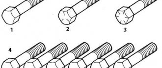
Selection of cutting tools according to steel tensile strength values N/mm2
To correctly select the cutting tool (annular cutter, countersink, core or step drill), check the “Short-term strength limit” value in the “Mechanical properties” section of the table for your material (Note: Further in the text - tensile strength).
This information is freely available; just enter the name or grade of your steel in a search engine.
Tensile strength is the maximum mechanical stress above which the material subjected to deformation (in this case, blade processing using a cutting tool) fails.
Tensile strength is indicated in the table of mechanical properties by the letters σв (MPa) and is measured in kilograms of force per square centimeter (kgf/cm2), and is also indicated in mega Pascals (MPa). In regulatory documentation and standards it is designated by the term “temporary resistance”.
σв — temporary tensile strength (short-term strength limit), MPa. 1 MPa = 1 N/mm²
The tensile strength of steel depends on the grade and varies from 300 N/mm2 for ordinary low-carbon structural steel to 900 and higher N/mm2 for special and high-alloy grades.
A cutting tool made of special high-alloy high-speed steel HSS-XE from the manufacturer Karnasch (Germany) is designed for drilling and machining holes in steels of regular and high quality with a strength of up to 900 N/mm2.
Additionally, the cutting tool is reinforced with a Gold Tech hardening coating, which effectively contributes to increased wear resistance of the metalworking tool.
For drilling and machining holes in durable and high-quality steels, it is recommended to use cutting tools equipped with carbide tips made of tungsten carbide or tools made entirely of special powder steel with the ability to process materials with a strength of up to 1400 N/mm2.
In the table below, you can familiarize yourself with some types of steels and their tensile strength values. Steels are divided into strength groups.
For example, for drilling ordinary structural steel C235 with a tensile strength of up to
360 N/mm2 is quite suitable for an annular cutter made of high-alloy, special steel HSS XE with the ability to drill materials with a strength of up to 900 N/mm2.
Or for countersinking embedded plates made of C390 steel, a conical countersink made of high-alloy steel HSS XE with a hardening coating is suitable to increase wear resistance to materials with a tensile strength of up to 900 N/mm2.
You can also bore or drill a hole in 15HSND bridge steel using an annular cutter made of high-speed high-alloy steel HSS XE with TIN or BlueTek coating. But even with correctly selected speeds and feeds, fewer of these holes will be made than when using tools with carbide cutting inserts, specially designed for processing strong, high-quality steels with a strength of up to 1400 N/mm2.
And of course, for processing stainless steels with a strength of more than 510 N/mm2, it is preferable to use cutting tools (core drills or conical countersinks) with replaceable carbide inserts. Metallrent.ru
To machine holes in special-purpose wear-resistant steels, a cutting tool specifically designed for this purpose is used. Manufacturer Karnasch (Germany) produces core drills specially designed for drilling such strong materials as Hardox or railway rails with the name Hardox-Line or Rail-Line.
The strongest tools available to the manufacturer are solid core and twist drills made of special powder steel. The strength of the materials for which they are intended is 1400 N/mm2 or up to 65 HRC.
Specific strength formula
R with the index “y” is the designation of this parameter in physics. It is calculated as PP (in writing – R) divided by density – d. That is, this calculation has practical value and takes into account theoretical knowledge about the properties of steel for use in life. Engineers can tell how the temporary resistance changes depending on the mass and volume of the product. It is logical that the thinner the sheet, the easier it is to deform.
The formula looks like this:
Ry = R/d
Here it would be logical to explain how the specific tensile strength is measured. In N/mm2 - this follows from the proposed calculation algorithm.
Ways to increase strength characteristics
There are several ways to do this, two main ones:
- addition of impurities;
- heat treatment, for example, hardening.
Sometimes they are used together.
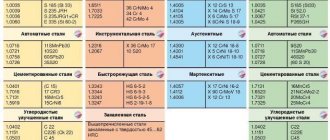
General information about steels
All of them have chemical and mechanical properties. Below we’ll talk in more detail about ways to increase strength, but first, let’s present a diagram showing all the varieties:
Also watch a more detailed video:
All of them have chemical and mechanical properties. Below we’ll talk in more detail about ways to increase strength, but first, let’s present a diagram showing all the varieties:
Carbon
The higher the carbon content of a substance, the higher the hardness and the lower the ductility. But the composition should not contain more than 1% of the chemical component, since a larger amount leads to the opposite effect.
Manganese
A very useful additive, but with a mass fraction of no more than two percent. Mn is usually added to improve machinability. The material becomes more susceptible to forging and welding. This is due to the displacement of oxygen and sulfur.
Silicon
Effectively increases strength characteristics without affecting ductility. The maximum content is 0.6%, sometimes 0.1% is enough. Combines well with other impurities; together, they can increase corrosion resistance.
Alloying Additives
You can also find the following impurities:
- Chrome – increases hardness.
- Molybdenum – protects against rust.
- Vanadium – for elasticity.
- Nickel – has a good effect on hardenability, but can lead to brittleness.
These and other chemicals must be used in strict proportions according to the formulas. In the article we talked about tensile strength (short-term resistance) - what it is and how to work with it. They also gave several tables that you can use while working. To finish, let's watch the video:
To clarify the information you are interested in, please contact our managers by phone;;. They will answer all your questions.