GOST standards
The main GOST for designations is 2317-72 - Conventional images and designations of welds. Besides this there is also:
- 21.502-2007 – Rules for the execution of design documentation for the creation of metal structures;
- Designation of welds in drawings GOST 5264-80 – Manual electric arc welding, as well as welded joints.
- Designation of welds in the drawings GOST 14771-76 - Arc welding in a shielding gas environment, as well as welded joints.
18130-79 and 13821-77
Currently, GOST standards adopted back in 1977 remain relevant. They prescribe the functional features of welding equipment, in particular, semi-automatic machines for argon arc welding. The list of requirements includes such as functionality, resistance to external factors, welding current values, availability of measuring and control instruments.
Such a variety of requirements does not allow us to formulate all the standards in one document, therefore this GOST refers to a number of minor regulatory documents. Thus, standardization of the argon arc welding process has a comprehensive approach. The total number of major and minor standards amounts to several dozen approved and adopted documents that are still in force at the present time, with the exception of some minor changes.
Basic designations
Welded structures use materials of different thicknesses, sizes and shapes; in addition, the parts may have different locations in relation to each other. The designation of a weld seam in the drawing directly depends on the relative position of the welded structural elements. Only 5 types of connections have been installed (according to GOST 5264 and GOST 14771):
- “C” docking;
- “C” end;
- "U" is angular;
- "N" overlap;
- "T" Tee.
A butt in the drawing is a connection of elements that are located on the same surface or plane. The process of welding parts occurs on adjacent end sides.
End connection “C” is the welding of elements along the end faces of parts whose side surfaces are together. This method is used when welding parts made of thin metal in order to eliminate the possibility of burn-through. The designation of welds in the drawings with the same letters, for example, butt and end, must have an explanation regarding the specific type of weld used.
Designation of welding seams in drawings with a capital letter H when welding using the overlap method. When welding, parts are arranged on parallel lines in such a way that one element partially overlaps the other.
T is the designation on drawings for a T-weld. The end part of one part is connected to the end part of another part at a certain angle (maybe 90 degrees).
The last type “U” - angular, is a seam that is obtained as a result of the arrangement of the welded elements at a right, acute or obtuse angle relative to each other. A weld seam in a drawing, regardless of what type of welding was used, can be designated as visible or invisible.
The visible type of seam is indicated by a solid line, the invisible seam is indicated by a dotted line. A single weld point, which is visible, is indicated in the drawings with a “+” sign; an invisible one does not have any designations.
If the drawing has seams that were made according to the same standards, then the welding drawings and designations will be the same, but this should be indicated in the technical requirements of this drawing.
In the drawings, identical seams can be numbered, but only if all seams are identical to each other and have a one-sided image, for example, only on the front or back side. If the seam does not have any designation, it should be marked on the drawing as a line - a leader that does not have flanges.
The designation of a weld seam in the drawing of a symmetrical product should be represented by leader lines, and the seams themselves should be depicted only on one of the symmetrical parts of the product. But this is only possible if there is an axis of symmetry.
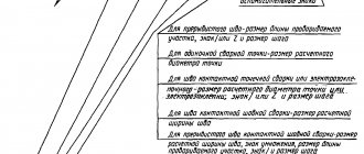
Example No. 1
In the picture above you see a butt seam in which one edge has a curved bevel. The connection itself is double-sided, made by manual arc welding. There is no gain on either side. On the front side the seam roughness is Rz 20 µm, and on the back side it is Rz 80 µm.
Example No. 2
Here you can see that the seam is corner and double-sided, it has no bevels or edges. This connection is made by automatic welding and using flux.
Example No. 3
Here we have a butt seam again, but without bevels or edges. The connection is one-sided, with a lining. The seam is made using heated gas and welding wire.
Types of seams according to GOST standards (squares 2 and 3 examples)
Possible methods of connecting two elements are closely discussed in GOSTs 14771-76 and 5264-80. There are the following types of welding joints:
- C – butt weld . The two elements being connected are in the same plane and at the same level. They are connected to each other by adjacent ends. This is one of the most popular connection options. Its peculiarity lies in the fact that the mechanical characteristics of the weld are very high, and the appearance of the finished structure is aesthetic. Along with the positive aspects, there are also negative ones. This type of connection remains technically difficult. It can only be performed qualitatively by experienced specialists.
- T – tee seam . This implies a connection of two elements located at an angle of 90 degrees relative to each other, and the junction has a T-shaped configuration. This is the most rigid connection option of all those considered. Therefore, it is not used in cases where some elasticity is important for the finished structure.
- N – lap seam . Two workpieces are located parallel, but not in the same plane. They are in contact with some overlap of the plane. A fairly strong and reliable connection method, but in terms of rigidity it is inferior to the T-type version.
- U – fillet weld . The ends of two workpieces are positioned at an angle of 90 degrees. The ends melt, resulting in a fairly strong and rigid connection.
- O – special types . This designates all other options for welding workpieces that are not described in the standard.
Both GOST standards mentioned at the beginning of the section have common features and overlap with each other. For manual arc connection according to GOST 5264-80:
- C1 – C40 butt;
- U1 – U10 corner;
- H1 – H2 overlap;
- T1 – T9 tee.
Performing welding work in an inert environment in accordance with GOST 14771-76:
- U1 – U10 corner;
- C1 – C27 butt;
- H1 – H4 overlap;
- T1 – T10 tee.
The example above contains the numbers just discussed. The second square contains information on the standard used - 14771-76. The third square describes the connection method - double-sided T-joint without beveled edges.
The need to use symbols
Scheme for designating welds on drawings in accordance with GOST
Properly compiled design documentation will ensure high-quality work of the entire chain of specialists - from the developer to the control department employee. Symbols for welded joints provide a complete list of characteristics: joining method, type and shape of the joint, geometric parameters, welding conditions, its sequence in the process, joint tightness, strength, etc.
Designations of welds on drawings are used not only during the manufacturing process, but also when checking the finished product. An employee of the control department checks the parameters of the finished product with the requirements of the design documentation: he can check the geometric parameters of the weld, the quality of work, etc.
5.917-71
This document was published on May 13, 1971 in accordance with the decree of the State Committee of Standards of the USSR. The given limits apply only to burners of the RGA-150 and RGA-400 types. They are used in argon arc welding with a tungsten electrode of aluminum, its alloys and stainless steel. Products that comply with GOST received a quality mark.
Expert opinion
Bagrov Viktor Sergeevich
Welder of the highest 6th category. He is considered a master of his craft, knows the intricacies and nuances of the profession.
Today, manufacturers of welding inverters operating in TIG mode do not adhere to these standards, however, thanks to modern technologies, the quality of the devices remains high.
Using auxiliary signs
Additional clarifications on the implementation of welded joints in accordance with GOST are indicated on the drawings using auxiliary signs:
Modern computer-aided design (CAD) systems are complex software products designed to assist engineers. Among the most well-known are AutoCad (on its basis, Autodesk Building Systems was developed for internal engineering networks), construction Allplan, and ATHENA for facade and metal structures. Of the Russian CAD systems, Compass and Monomakh have proven themselves well.
Auxiliary symbols for designating welds
General issues
Argon arc welding is called welding with the formation of an electric arc in an argon environment. One of the electrodes is the surface of the part. The second electrode may be consumable or non-consumable. The non-consumable electrode is usually made of tungsten. In regulatory documents, argon arc welding can be designated by the following abbreviations:
- RAD – manual argon arc welding. In this case, a non-consumable electrode is used.
- AMA is argon arc welding, carried out with non-consumable electrodes, but in automatic mode.
- AADP – automatic welding with consumable electrodes.
In the international classification, this type of welding is defined as TIG - Tungsten Inert Gas or GTAW - Gas Tungsten Arc Welding, which translated means “welding in an inert gas environment”. Often this gas is argon.
An inert gas was chosen to create a protective environment due to the lack of chemical interaction with metal and other gases. Since argon is heavier than air, it displaces atmospheric oxygen and hydrogen from the weld formation zone, which eliminates the appearance of pores and cracks in the metal, and also prevents the formation of a layer of oxide film.
Welding technology boils down to the formation of an arc between a tungsten electrode and the surface. Gas enters the welding zone through a special torch nozzle. Unlike welding with a consumable electrode, here the additive is excluded from the electrical circuit, and is supplied to the bath area separately in the form of a rod. Manual welding differs from automatic welding in that in the first case the welder himself holds the torch and adds the additive, and in the second the process is automated. The technology also differs in the method of arc formation.
For a number of reasons, the arc cannot be formed by simply touching the electrode, so the installation provides for parallel operation of the oscillator. It is necessary to understand that welding can be carried out with both direct and alternating current. According to the method of connecting the electrode, direct and reverse polarity are distinguished. Before carrying out preparatory work, it is necessary to select the necessary parameters for each specific metal.
The main issues were discussed above, since many parameters are subject to standardization. GOST for argon arc welding is not limited to just one document. Standards have been determined for burners, processing and size of seams, working with aluminum, for filler wire, for equipment and electrodes. But, before presenting a list of these documents, let’s look at the issue of standardization.
What is a welded joint
The welding process is a technological operation of forming a monolithic joint. The area where the material of the joined parts melted and solidified is called a weld.
Kinds
The welded joint is divided into:
- Stykova. The connection is formed along the end surfaces of the parts. It is carried out with or without edge processing. Marking "C".
- Overlapping. The planes of the parts are parallel to each other and partially overlap one another. Marking "N".
- Tavrovy. The end of the part is adjacent to the plane of another part at an angle. The seam is located along the joint. Marking "T".
- Angular. The main planes of the joined parts in the welding zone are located at an angle to each other. Marking "U".
- Tortsovy. The semi-finished product is pressed against the side surfaces. The seam is formed by fusing metal onto the ends of the products.
The seam is performed:
- Unilateral. Deposition is carried out on one side of the connection (joint).
- Bilateral. Processing occurs on both sides.
Square No. 4, welding methods
How are the different types of seams designated?
The standards also contain designations for welding methods; here are examples of the most common ones:
- A – automatic submerged without cushions and linings;
- Af – automatic submerged arc on a pad;
- ИH – in an inert gas with a tungsten electrode without additives;
- IHP – method in inert gas with a tungsten electrode, but with an additive;
- IP – method in inert gas with a consumable electrode;
- UP is the same thing, but in carbon dioxide.
In square No. 4 we have the welding designation UP - this is a method in carbon dioxide with a consumable electrode.
Types of welded joints
The type is determined by the relative position of the parts being connected. According to GOST 5264-80 and GOST 14771-76, there are five types of welded joints:
| No. | Name | Description | Marking |
| 1 | Butt | The elements to be joined are placed in the same plane, welded at adjacent ends, and edge processing is possible. Requires precise adjustment of joined parts and is highly durable. | WITH |
| 2 | Lap | Parallel planes of parts overlap each other. They are inferior to butt joints in terms of reliability under load, and are not so demanding in terms of accuracy of fit. | N |
| 3 | Tavrovy | The end of the part is welded to the surface of another part of the structure vertically or at an angle. Not recommended for bending loads. | T |
| 4 | Angular | The surfaces of the joints to be connected are inclined relative to each other (the angle of contact of the edges is more than 300), welding is carried out at the ends of the products. | U |
| 5 | Tortsevoy | The ends of the nodes whose side surfaces are in contact are connected. To do this, a layer of metal is fused to the ends. Used when connecting thin elements to avoid burning. | WITH |
According to GOST, welded joints can be single-sided (SS) or double-sided (BS), depending on the metal deposit on one or both sides. There are also single-layer and multi-layer welding.
The choice of welding seam is determined by the design requirements for the connection.
Types of welded joints
Creating an Assembly
To create an assembly, you need to make 3D models of all the parts included in it.
You can create the details yourself or download them from the link at the end of the article.
It is advisable to save all documents related to the assembly in one folder.
For each part, add a specification object: Specification→Add object→Details→Create.
Create an assembly: XYZ orientation, insert the Plate first, then the Cylinder and Eye. More details and overlapping mates.
Then we create specification objects for the assembly: Specification → Create specification objects.
Now a new document has appeared in the folder with assembly documents - a specification containing information about the components of the assembly.
Assembly drawing of a welded joint
Let's create an associative assembly drawing of the product Support.
Turn off the left view of the product and insert two views into the field of the A4 drawing.
As you can see, the views are too bulky, so let's set the scale for them to 1:2. Select them, in the context menu (RMB) select the Scale command, select 1:2.
The front view should be replaced by a frontal section, so we delete it.
Create a cut.
This cut needs to be adjusted because the eyelet should not be shaded.
Call the Drawing Tree window: View→Drawing Tree. We get to the Eyelet component and in the Context menu select the Don’t cut command. Rebuilding the assembly
It is also necessary to remove the letter designation of the cut and the trace of the cutting plane. To do this, we create invisible layers to which we transfer these designations.
Working with specifications
Now we arrange the positions of the parts in the drawing arbitrarily; we will edit them later.
To edit positions in a welded joint drawing, you need to link it to a specification file. Open the specification, open the Assembly Management window → click “+” Connect document and add a link to the assembly drawing.
Argon arc welding of stainless steels
These instructions apply to manual and automatic welding in argon of austenitic stainless steels.
In accordance with the requirements of the instructions, it is allowed to weld parts made of stainless steels of type X18N9T with parts made of low-carbon steel and nickel.
The instructions should be used to guide the design, development of technological processes, manufacturing, inspection and acceptance of welded assemblies.
Deviations (tightening or reducing requirements) from these instructions can be included in the technological documentation for the product in agreement with the chief technologist and the customer’s representative.
Materials, equipment, devices, tools are given in the Appendix.
Copper argon arc welding must be carried out by certified welders in compliance with the safety rules set out in the safety instructions.
Allow certified welders who have the right to perform welding work on stainless steels to perform welding work.
Preparing parts for welding
Remove oil and other grease from the parts to be welded by wiping with a cotton cloth moistened with gasoline.
After degreasing, further prepare the parts for welding by chemical etching or mechanical cleaning of the welded edges.
Perform mechanical stripping or etching of welding wire in accordance with the relevant technical specifications.
Mechanically clean the welded parts on both sides to a metallic shine to a width of 15-20 mm using a steel brush or scraper.
Note - Burrs, cracks, and delaminations are not allowed on the edges of parts prepared for welding.
After mechanical cleaning, wipe the edges of the parts with a cotton cloth moistened with gasoline.
Perform chemical etching of stainless steel parts in accordance with the relevant technical specifications.
Anneal thin-sheet parts in a vacuum oven at a temperature of 900-950 °C for 20-30 minutes. Working vacuum 5×10⁻⁴ mm Hg.
Use parts and welding wire prepared in accordance with these instructions for welding no later than 72 hours.
Welding
Select the collet, nozzle and tungsten electrode of the torch based on the ratios indicated in Table 1.
Table 1
| Diameter of tungsten electrode, mm | 1,5-2 | 2,5-3 | 3,5-4 | 4,5-6 |
| Nozzle outlet diameter, mm | 5-7 | 7-9 | 9-12 | 12-14 |
| Argon consumption, l/min | 2-3 | 4-5 | 6-8 | 10-18 |
Note - Using the recommended ratios allows for good protection of the weld area from environmental influences.
Wipe the collet, nozzle and tungsten electrode of the torch with a cotton cloth moistened with alcohol. Wipe down every time before starting a shift.
Install a multilayer mesh with a hole for the tungsten electrode between the collet and the torch nozzle.
Fix the tungsten electrode in the burner so that its protrusion from the burner nozzle does not exceed 5-12 mm.
Perform operations before starting the shift.
Check the appearance of the welding installation, make sure that there are no foreign objects and that the installation is grounded.
Supply the installation with supply voltage from the power distribution board.
Open the valve of the argon cylinder. Using the reducer, set the gas flow rate using the rotameter according to Table 2.
Weld using direct current of straight polarity.
Assemble parts or assembly units for welding using a jig and tack welded edges at diametrically opposite points using the mode according to Table 2.
Remove the jig from the assembly after tacking and install it in the welding fixture.
Welding is carried out in the recommended mode according to Table 2.
Note - If the weld seam of the assembly is closed, overlap it along the length by 10-20% of the perimeter of the seam.
Upon completion of welding, remove the welded assembly from the fixture.
Inspect the assembly using a magnifying glass for defects in the weld. The seams must have a smooth or finely flaky surface without visible defects: lack of fusion, undercuts, pores, cracks, unfilled craters.
Note - Oxidation of the main zone (tarnish color) is not a rejection sign.
At the end of the work shift, turn off the unit and close the cylinder reducer valve.
Cleaning of the weld seam in order to identify scale, splashes and influxes of metal should be carried out according to the route map for the manufacture of the unit.
The grades of steel welding wire (filler material), depending on the grades of steel of the parts being welded, are indicated in Table 3.
Table 2 - Approximate welding modes for stainless steels Thickness, mm Welding mode Argon consumption l/min Welding current, A Arc voltage, V Welding speed, m/hour Tungsten electrode diameter, mm Filler wire diameter, mm In the arc zone to protect the seam For blowing
| Automatic welding, tungsten electrode without additive | |||||||
| 0,8 | 60-100 | 9-10 | 30-50 | 2,0 | — | 6-8 | 1-2 |
| 1,0 | 70-100 | 9-10 | 25-40 | 2,0 | — | 6-8 | 1-2 |
| 1,5 | 100-160 | 10-12 | 20-35 | 3,0 | — | 9-10 | 2-3 |
| 2,0 | 160-180 | 12-13 | 20-30 | 3,0 | — | 10-12 | 2-3 |
| 2,5 | 180-200 | 12-15 | 20-30 | 3,0 | — | 10-12 | 3-4 |
| 3,0 | 200-220 | 12-15 | 20-30 | 4,0 | — | 12-14 | 3-4 |
| Automatic welding, tungsten electrode using additives | |||||||
| 1,0 | 70-120 | 9-10 | 20-25 | 2,0 | 0,5-0,8 | 6-8 | 1-2 |
| 1,2 | 70-120 | 9-10 | 20-25 | 2,0 | 0,8-1,2 | 6-8 | 1-2 |
| 1,5 | 120-150 | 10-12 | 20-25 | 3,0 | 1,2-1,6 | 9-10 | 2-3 |
| 2,0 | 170-200 | 10-12 | 20-25 | 3,0 | 1,2-1,6 | 9-10 | 2-3 |
| 2,5 | 180-210 | 12-15 | up to 20 | 4,0 | 1,6-2,0 | 10-12 | 3-4 |
| 3,0 | 200-240 | 12-15 | up to 20 | 4,0 | 1,6-2,0 | 10-12 | 3-4 |
| Manual tungsten welding | |||||||
| 1,0 | 45-65 | — | — | 2,0 | 1,2-1,6 | 5-8 | 1-2 |
| 1,5 | 45-70 | — | — | 2,0 | 1,2-1,6 | 5-8 | 1-2 |
| 2,0 | 70-90 | — | — | 2,0 | 2,0 | 8-10 | 2-3 |
| 2,5 | 80-100 | — | — | 3,0 | 2,0-2,5 | 10-12 | 2-3 |
| 3,0 | 100-130 | — | — | 3,0 | 2,0-2,5 | 10-12 | 2-3 |
Table 3 - Selection of welding wire grade depending on the grade of steel being welded Grade of steel of welded parts Grade of steel welding wire GOST 2246-70
| 12Х18Н9 | Sv-04Х19Н9 |
| 12Х18Н9Т | Sv-06Х19Н9Т |
| 12Х18Н10Т | Sv-07Х19Н10Б |
Welding quality control
Carry out continuous quality control of welds after completion of welding using a magnifying glass in accordance with the drawing.
Inspect the welds along the entire length on both sides.
Carry out grading of defective welds in accordance with the requirements of Table 4.
It is allowed to weld defective areas of welds no more than twice.
Completely reject welded assemblies that have defects in the welds, the dimensions of which are larger than those allowed for correction.
Table 4 - Sorting of seam defects based on the results of visual inspection Name of defects Number and size of defects per 100 mm of seam Allowed to be left without correction Allowed for correction
| Displacement of the edges of the parts being welded | Up to 0.1δ along the entire length of the seam | More than 0.1δ along the entire length of the seam |
| Lack of penetration | Not allowed | Any length |
| Cracks | Not allowed | Total length up to 15 mm |
| Burn-through | Not allowed | No more than 1 |
| Undercuts | Depth up to 0.1δ | Depth more than 0.1δ |
| Sinks | Depth up to 0.2δ | Depth more than 0.2δ |
| With a diameter of up to 0.5δ - no more than 2 pieces | With a diameter of up to 0.5δ - no more than 5 pieces | |
| Pores and tungsten inclusions | Diameter up to 0.4δ - no more than 3 pieces | With a diameter of more than 0.4δ - up to 0.1δ no more than 6 pieces |
| Accumulations of small pores and tungsten inclusions | Total area up to 5 mm2 | Total area up to 15 mm2 |
| Penetrations that do not present porous sagging and do not interfere with further assembly | 100 % |
Note - When measuring defects in welds, it is necessary to use a tool: a caliper, a probe, special templates, or others.
Materials
- Lanthanated tungsten in the form of rods with lanthanum content (1.3-1.8)% TU 48-19-27-88.
- Argon gas, highest grade GOST 10157-79.
- Steel welding wire GOST 2246-70.
- Cotton fabric of calico group GOST 29298-92.
- Knitted gloves GOST 5007-87.
- Gasoline "Galosh" TU 38-401-67-108-92.
- Technical ethyl alcohol GOST 17299-78.
- High purity argon type “HF” TU 6-21-12-94 (for stainless steel parts with a thickness of 0.15-0.8 mm).
Equipment, devices and tools
- Power source type PS-300, PS-300M, PSO-500, VKSM-1000, UDG-3010 UZHLU or UDG-101 for shielded gas welding with a set of welding torches, collets and nozzles.
- Rheostat type RB-200 or RB-300.
- Balloon reducer TU 26-05-90-87.
- Rotameter type RM-11 or RM-1 GOST 13045-81.
- Pressure gauge DM 60-0.2 MPa-4 GOST 2405-88.
- A set of technical rubber tubes GOST 5496-78 (for supplying protective gases and water to the burner).
- Protective welding helmet with a set of protective welding glasses ES-100, ES-300, ES-500 TU 38.11.0208-86.
- Sealed protective glasses GOST 12.4.001-80.
- Steel brushes made of stainless wire with a diameter of (0.2-0.3) mm GOST 18143-72.
- Assembly and welding devices.
- Magnifying glass LP-1-5 GOST 25706-83.
- Calipers GOST 166-89.
- Metal ruler GOST 427-75.
- Device for laminar gas flow for the burner.
weldworld.ru
Drawings: GOST requirements
Welding, a designation on a GOST drawing, where there are identical components of one part that were welded with seams of the same type, can be designated as leader lines. The seams can be indicated only for one part of the part; the best option is an image next to which there is a line - a leader.
Some welds may not be marked with leader lines in the drawing, but are indicated as welding explanations in the technical requirements and notes to the drawing. The designation of the weld seam in the drawing is a mandatory condition, it is in the technical requirements, it must contain information about the type, dimensions of the parts and their design features, the location of the weld seams in the cross section.
All seams or a group of seams in the drawing are given the same set of requirements, which should be located either in the table or in the technical description.
Welding (designation on the GOST drawing) must fully comply with all established requirements. A well-drawn drawing is the key to fast and efficient work by welders. A drawing that is not made in accordance with GOST requirements will not be accepted by the authorities.
Sources
- https://intehstroy-spb.ru/spravochnik/oboznachenie-svarnyh-shvov.html
- https://protect.gost.ru/document.aspx?control=7&id=161216
- https://BurForum.ru/svarka/oboznachenie-svarki-na-chertezhah-po-gost.html
- https://rosstandart.msk.ru/gost/001.025.160.040/gost-14771-76/
- https://metall4all.ru/gost/gost-14771-76/
- https://ecat.simbexpert.ru/Index2/1/4294850/4294850476.htm
7871-75 and 2246-70
The introduced GOST concerns wire made of aluminum or alloys. Manufacturers use it, since the document regulates the possible values of wire diameter. Among all other requirements, standards for the chemical composition of consumables have been determined.
There are several types of wire, differing from each other in the quantitative content of elements (magnesium, manganese, aluminum, iron, silicon, titanium, beryllium, zirconium). Most popular brands:
- SvA99;
- SvA97;
- SvA85T;
- SvA5;
- SvAMts;
- SwAMg3;
- SvAK5.
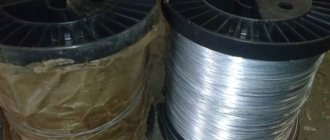
The presence of impurities is allowed. The manufactured wire is tested, including for strength. The table shows the values of the maximum loads at which rupture occurs. Acceptance of materials is carried out in batches. One batch must contain wire with the same parameters. The appendix to the document specifies the conditions for storing and transporting the wire. Since it is supplied in coils, the dimensions of the coils are also subject to normalization.
Steel wire must meet the requirements of GOST 2246-70. Popular types:
- Sv-08;
- Sv-08A;
- Sv-10GA;
- Sv-08GSMT.
This is not a complete list of wire brands. They are divided not only by characteristics, but also by applicability. There are materials for the manufacture of electrodes, wires for welding copper-plated surfaces, and wires for surfacing.
What electrodes should be used to cook steel 12x18n10t.
Nowadays, almost all people have access to all brands and types of electrodes. Electrodes are divided into different classes according to their characteristics, for example they can be divided into electrodes for welding high-alloy and low-alloy steels. Electrodes are also divided into classes based on coating material: basic, acidic and regular. The list of classes into which electrodes are divided is very large, so there is no point in listing it completely. One of the types of electrodes are electrodes for welding steel 12x18n10t , that is, they are intended for welding chromium-nickel steels. This type of steel is used in cases where the product must be as resistant to corrosion as possible and not succumb to other environmental factors. Also, products that are welded with electrodes for welding steel 12x18n10t are subject to increased requirements for resistance to intercrystalline corrosion.
Stainless steel products are highly valued all over the world, so the popularity of electrodes for welding steel 12x18n10t continues to grow every day. However, many people are also attracted to these electrodes by their excellent combination of price and quality. Truly, such a combination is extremely rare, so this is precisely one of the most important advantages of these particular electrodes.
Now let's talk about the process of welding with electrodes for welding chromium-nickel steels. Welding with these electrodes is carried out in all spatial positions using direct current of reverse polarity. Also, these electrodes also have such qualities, for example, stable arc burning, low metal spattering, excellent seam formation and easy separation of slag from the surface of the product.
Immediately before starting welding, you need to calcinate the electrodes for welding 12x18n10t steel in a special furnace for calcining electrodes at a temperature of 300 to 350 degrees Celsius for one hour. After complete cooling, the electrodes are ready for use. Seams welded with these electrodes can be exposed to temperatures up to 350 degrees. Welding with electrodes for welding chrome-plated steel can be done either manually or with an inert gas arc.
Also, for welding with these electrodes, such types of welding as plasma welding, pulsed-arc welding, spot and roller welding, welding in an active gas environment, submerged arc welding are also used, and resistance welding is also possible. During welding, a porous oxide layer is formed, which contains chromium. This leads to a decrease in corrosion resistance, so if you need high corrosion resistance, then you need to subject the material to subsequent processing so that the product remains the same after several decades.
For a long time now, many economical people have continued to weld chrome-plated steel products for their homes. They order them without any problems through the “Contacts” menu item and remain satisfied.
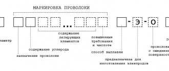
- Decoding the electrodes
- Electrodes by Brand
Electrodes Uoni 13 45 Electrodes ANZHR Electrodes ProfHelper