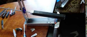
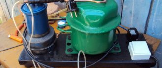
Yielding to temptation, I bought a hot air soldering gun on AliExpress. The issue price is 600 rubles. Accordingly, I began organizing the appropriate “wiring” of the device. I started with the fan control. The fan in the hair dryer is powered by a direct current of 0.25 A and a voltage of 24 volts. For this purpose, a switching power supply from a Canon K30232 printer is exclusively suitable, of which there are a great many on free secondary sale, and at a low price. And here the main convenience is not even that it is at the required 24 volts and produces quite sufficient current up to 0.7 A, but that the circuit already provides a trimming resistor, which is extremely necessary when adjusting the output voltage in the required range.
Power supply from Canon K30232 printer
I didn’t buy my own power supply, it was in stock, although it had been faulty for two years already, but when I really needed it, I managed to somehow quickly fix it.
Operating principle and general characteristics
A soldering station, or sometimes called a machine or installation, is a device that is widely used in everyday life, in electronics, and electrical engineering. The main purpose of this equipment is group or single soldering of parts.
The design of this equipment includes the following components:
- A control unit that controls the operating parameters of the device.
- A soldering iron designed for soldering.
- Tweezers involved in the assembly/disassembly of elements installed on a printed circuit board.
- A hair dryer, which is designed to heat the assembly area. It can be used to perform both single and group operations.
- A heat source used to heat a printed circuit board to a process-specific temperature.
- A device for removing excess tin.
- Auxiliary equipment - stands, etc.
- Bracelets that relieve static tension.
Homemade soldering station
The simplest stations include soldering irons, a control device and soldering iron stands. The key difference between a station with a hair dryer and a traditional soldering iron is that the use of this machine allows you not only to connect parts together, but at the same time optimize the temperature regime. The station includes various devices that not only increase productivity, but also ensure worker safety.
And of course, we must not forget that soldering stations with a hair dryer are equipped with a device for removing static voltage.
The characteristics, as well as the operating principles of the station with a hair dryer, are not very complicated, and this allows you to build a soldering station with a hair dryer with your own hands.
Main characteristics of a soldering hair dryer
There are several parameters that you should pay attention to when choosing a hair dryer for soldering - voltage and power.
To successfully solder computer chips and radio components at home, the power should be at least 100 watts, but more is better.
Let the resulting temperature be higher than necessary, it can be adjusted using a relay, wire or distance to the heated surface. In industrial soldering guns, the power reaches 1.7 kW or more.
Recommended voltage range 24-36 Volts. Smaller values will not allow you to achieve the required power, and larger values can be dangerous. Additionally, the voltage will depend on the resistance in the heater wire. It is recommended to use nichrome wire with a resistance of 6 Ohms for a voltage of 24 Volts.
Recommendations for assembling a homemade soldering station with a hair dryer
The key requirement that can be presented to a homemade soldering station with a hair dryer can be formulated as follows - it must provide an air flow heated to a temperature of at least 850 ⁰C. In this case, the power of the heating element in the soldering station should not exceed 2.6 kW.
In addition, all the components of this soldering machine with a hair dryer should not be expensive and should be affordable. By the way, household hair dryers do not meet any of these requirements. Most often, home craftsmen strive to make either a manual or stationary hot air gun.
Oddly enough, a stationary product is easier to assemble. This is due to the following reasons - no one limits the master in terms of size and weight characteristics. There is no need to manufacture a pistol grip, which is necessary to control the device.
Soldering hair dryer power supply circuit
A hot air gun, in a stationary version, works as follows - the heat emitter stands motionless on the work table, and the part needs to be moved. This solution leads to complications during soldering. To increase soldering efficiency, it is advisable to use a hand-held soldering iron (hot air gun). Such a device should be small in size and can be operated with unprotected hands.
One of the main questions that will confront a craftsman who decides to assemble a soldering station with his own hands is something like which heating tool is appropriate to use. As already noted, the components that make up a household hair dryer do not meet the requirements for devices of this type. Therefore, it is unacceptable to use them when creating a homemade soldering station.
The practice of creating homemade stations suggests that the best option is to make your own heater from nichrome wire. Its cross section should be in the range from 0.4 to 0.8 mm. It should be understood that using wire of a larger cross-section will provide a greater power reserve, but it will be quite difficult to obtain the temperature necessary for operation.
Nichrome wire heater coil
By definition, the heater should not be large. To do this, the heating coil should not exceed 4 – 8 mm in outer diameter. As a base on which the heating element will be fixed, it is necessary to use a material with high resistance to high temperatures. It could be ceramics. By the way, a part of this type, installed in a household hair dryer, may well be suitable.
A small fan can be installed as a supercharger. By the way, it can also be removed from an old hair dryer.
The fan should provide an air flow of 20-30 liters per minute. Another option is an air compressor for aquariums. To improve its performance, it is necessary to supplement it with a receiver. You can use an ordinary plastic bottle for it.
Making a body for a hair dryer can be done based on several options. You can use materials that show high resistance to temperature, for example, ceramics, but such a solution will make the structure more expensive. You can reduce the cost by using partial thermal insulation of the channel through which hot air moves.
Hot air gun body for soldering
For the body of a self-made hot air gun, you can use the body from a household appliance. There are some conditions - for example, the body must be sufficiently voluminous, and the nozzle must be made of heat-resistant materials or metals.
Another concern that the master will face is ensuring the operability of the device. In particular, the design of a homemade device must include a trigger mechanism (switch) and an element responsible for adjusting the air flow parameters, namely its speed and temperature. To solve these problems, rheostats must be installed in the electrical circuit, which allow smooth power adjustment.
The assembly of the product begins with the manufacture of a spiral. When winding it, it must be taken into account that its resistance should be in the region from 75 to 95 Ohms. The spiral must be wound on a reliable insulator, and the top must be covered with an insulator, for example, asbestos or fiberglass. After assembling this assembly, the ends of the spiral should come out.
The finished element must be installed in a previously prepared channel of the housing, that is, it must be lined with a layer of thermal insulation. After installing the spiral in place, it can be connected to the power wiring, which includes the switch.
IMPORTANT! When performing work, you must constantly remember thermal insulation.
An air heater must be mounted in the rear of the housing. If the dimensions of the supercharger do not allow it to be installed in the housing, then it is quite possible to secure it from the outside. An air duct must be connected to supply air.
Features of soldering hair dryers
A soldering hair dryer is used when working with low-melting alloys and metals. In addition, it is often used to remove paint coatings from the surface of old parts and when they are heated. The temperature of the air leaving the hair dryer nozzle reaches 800 °C. It is regulated using a special relay, but besides this, the temperature depends on the voltage used, the fan and the distance to the heated object.
Working with a soldering iron
The nozzle is made of heat-resistant materials and has a specific design that is convenient for use in one hand, if it is not a stationary soldering gun.
Rules of use and safety precautions
When working, you must strictly observe safety precautions and rules for using such devices. Firstly, fire safety must be observed.
During operation, it is unacceptable to suddenly change the temperature in the heating element.
During work, you must be careful and avoid touching heated elements. Moisture must not get into the body or inside the hot air gun.
Attachments can only be replaced after the hair dryer has cooled down.
The workplace must be well ventilated.
Equipment design features
A similar device is often used to soften or melt plastic, thin metal and tin.
Such processing occurs due to the blowing of a heated spiral. The air heats up and transfers thermal energy to the material. To make such a functional device with your own hands, you need to understand its design . This includes:
- heater, that is, a housing represented by a tube;
- a supercharger, the function of which is performed by a pump or fan;
- pen;
- switch.
In some cases, a temperature sensor and various attachments are additionally installed.
DIY soldering station diagram, element base
The key tool of a soldering station is the soldering iron. If, when assembling the station yourself, you can use some elements removed, for example, from household appliances that have expired. Then the soldering iron should be new without any dispute. Many craftsmen prefer Solomon products and some others.
Soldering station diagram
After selecting a soldering iron, you can begin to select a diode bridge for the electrical circuit and transformer. In order to obtain a voltage of 5 V, a linear stabilizer with good cooling is needed. As an alternative, you can consider using a transformer that has a winding available that is necessary to service the digital unit.
A schematic diagram of a homemade device can be found on specialized forums.
What do you need to know about this technique?
A soldering hair dryer is a modern electrical device that allows you to heat metal taps in a short period of time. Thanks to its high-quality assembly and ease of operation, the device is suitable for professional and even novice welders .
A soldering gun is almost never used separately, since precise direction is important during the work process. Therefore, experienced craftsmen often use entire soldering stations. We are talking about a semi-professional heating device, represented by a soldering iron and a welding heater. Such equipment is suitable for working with components of electrical networks and circuits. Also, thanks to the device, it will be possible to perform heat treatment of small parts.
It is worth noting that any soldering guns differ in their characteristics:
- diameter within 2–5 mm;
- power about 450 W;
- fan productivity is maximum 30 liters per minute;
- reaching a temperature of about 500°C.
Purpose of buttons and firmware options
The front panel of the station must be equipped with control buttons responsible for performing the following functions:
- Lowering/increasing the temperature in a certain step, for example 5 or 10 degrees.
- Installation of pre-selected modes.
Setting up a soldering station
Instead of control buttons, you can use an external device (programmer) or perform firmware inside the circuit. Setting the temperature is quite simple.
Electrical circuit of a hair dryer
Most construction hair dryers and hair dryers have the electrical diagram below. The supply voltage is supplied through a C6 type plug using a flexible cord. Capacitor C1 serves to suppress noise emitted by the motor brush assembly. Resistor R1 serves to discharge capacitor C1 after disconnecting the plug from the socket to prevent electric shock to a person when touching the pins of the plug. In some models, elements C1 and R1 are not installed.
The hair dryer operating modes are controlled using switch S1. In its position shown in the diagram, the hair dryer is off.
When the switch slide is moved one step to the right, its moving contact closes pins 1-2 and the supply voltage through the rectifier diode VD1 is supplied through the current-limiting coil H1 to the motor and heating coil H2. The diode cuts half of the sine wave and thus reduces the rotation speed of the impeller and the heating power of the H2 coil by half.
When you move the engine one more step, contacts 1-2-3 close, the heating element and the motor are supplied with all the mains voltage and the hair dryer operates at full power.
Typically, hair dryers are equipped with DC motors designed for a supply voltage of 9-12 V. The H1 coil is used to reduce the voltage. To convert alternating current to direct current, a diode bridge VD2-VD5 is used. Electrolytic capacitor C4 smoothes out ripples. Spark suppression capacitors C2-C3 perform the task of extinguishing sparks in the brush-commutator assembly of the engine and suppressing radio interference.
Button S2 is used to switch the hair dryer to cold air mode. When you press it, the H2 coil stops heating.
To protect the hair dryer from overheating, which can occur due to a decrease in impeller speed in the event of an engine malfunction, a thermal protection element St is used, which opens the supply voltage supply circuit to the H2 heater when the maximum permissible air flow temperature is exceeded.
From a soldering iron and a dropper
To make a soldered hair dryer with your own hands, you can use a simple soldering iron with the protective casing removed from it.
When taking it as the basis for a future heater, it is necessary to modify the design, which consists of the following:
- First, the tip is removed from the working part of the soldering iron, after which the mica tube with the nichrome winding placed underneath it is completely pulled out of the wooden handle-holder.
- Then the power wires suitable for the heating element are disconnected and also pulled out of the wooden holder, but from the other side.
- After this, a hole of the required size is drilled in the side of the handle, into which the previously disconnected network wire is threaded (towards the working part).
- At the next step of making a soldering gun, take a dropper, from which the tip is cut off in the area where the rubber skirt is located. Then the exposed part of the tube is inserted into the network hole of the wooden handle.
- Next, the rubberized seal (skirt) of the dropper is pressed with force against the end part of the holder, ensuring reliable sealing of the docking area.
- Upon completion of these actions, the ends of the drawn power wire are reconnected to the nichrome winding and reliably insulated.
- A piece of telescopic antenna of suitable diameter is inserted into the hole where the soldering iron tip was previously located and carefully clamped with a locking screw.
The tightness of the inlet hole in the handle will ensure effective inflation with cold air coming from the compressor station.
At the final stage of assembling the soldering gun, you should return the heating tube with the nichrome winding to its place, having previously wrapped it with several layers of aluminum foil.
Then the heater prepared in this way is recessed into a wooden handle and securely fixed using a flexible copper wire wound along the entire length of the protective coating.
Soldering gun controller, DIY
Why not make yourself a soldering iron station, I thought? And he began to slowly collect material, read about ready-made devices, and collect components. As a result, we got the device that I want to talk about. There will be some photography, amateur radio, Arduino programming and homemade or DIY projects. And one more thing: I understand that buying ready-made is much cheaper than making it yourself. Those who are not intimidated, who like to do things with their hands and program AVR microcontrollers, are welcome. The hair dryer itself, or the handle, was sold in a Ukrainian online store as a spare for a Chinese station with a difficult-to-remember name. A stand with a built-in magnet was also purchased there. The price was very reasonable, it looked like they were selling off the leftovers. Now it is out of stock, but the same is available on Ali, here and here, and also a stand: one and two. The handle contains a heater with a temperature sensor, a turbine fan and a reed switch. I just added a button with a resistor, but more on that below. I bought this set of attachments on Ali. The controller assembled it himself. It contains a PID temperature controller, allows you to work with two setpoints, and regulate fan speed. The temperature or fan speed is shown on the digital display. The stand holds the hairdryer at 100 degrees. When removed, it enters the mode within 2..3 seconds and a short sound signal is generated. If you stay on the stand for more than 10 minutes, the hair dryer turns off, and sound signals are generated at the 8th and 9th minutes. Temperature and fan speed are set using an encoder. PID controller coefficients - in the port monitor dialog box when connected to a computer. Controls
On the front panel there is a power switch and an encoder that adjusts the parameter. A short press on the encoder switches the temperature or fan speed settings. Hold for up to 4 seconds. — switches the mode of setting the first or second temperature settings. When you turn off the toggle switch, the hair dryer cools and then disconnects the device from the network. When working with a hairdryer, the display shows the current temperature. When on the stand - set or flow temperature, this is selected by holding the encoder button for more than 4 seconds. A button mounted on the hair dryer itself allows you to work with a different temperature setting while it is pressed. For example, if you need to “fry” for a short time at a higher temperature. Links to Ali: 9 pin connector, encoder.
Indication
Indication elements: three-digit digital indicator and four lights. First light: The display shows the temperature. Second - the second task is displayed. the third (green) - displays the temperature setting, the fourth (blue) - displays the fan performance. Links to Ali: neon lights, green and blue.
Frame
The Z2P case was purchased from a Ukrainian online store.
The front panel drawing was made in Corel draw. There is also a sketch for cutting holes. Cutting was carried out using a CNC laser. It is described in more detail at the end of this review. The front panel is printed on plain paper. After cutting the holes, it is run through a laminator and secured to the plastic with double-sided tape. Front panel photo
Components, assembly
The donor of the indicators was a part of an unknown creation of USSR engineers.
The device was purchased at a flea market several years ago. One indicator was already broken, but for it they asked for a sum equivalent to the cost of a bottle of vodka. Personally, I admire the electronic non-household industry of the USSR. Using a CNC spindle motor with a cutter, I carefully cut out three indicators with decoders.
More photos of the display device
Radio parts and components were purchased on Ali and in Ukrainian online stores. Most were found in bins. Links to Ali: power and heater connectors 2 pins, signal connectors and Dupont Arduino pro was chosen as the brain. It is not expensive and copes with all functions. Purchased in Ukraine, here. The printed circuit board is drawn in Sprint layout, etched in peroxide with citric acid. Drilling and milling are carried out using a CNC machine. Printed circuit board
The 24 volt power supply was torn from some kind of adapter. Assembled board
Another photo of the assembled board
Boards in housing, test run
Assembled device
More photos
Scheme
Schematic diagram of the device
Display device
Program
Control program text
// Hot air gun temperature controller // Arduino pro mini // 5V; 16 MHz; 328P // Settings #define FAN_MINIMAL 20 #define SV_MINIMAL 100 #define SV_MAXIMAL 450 #include // Display #define HV 4 #define DATA 5 #define LATCH 11 #define CLK 18 byte regL, regH; // Control #define ENC_CLK 3 #define DIRECT 7 #define BUTTON 8 #define POW_SW 9 int bt_timer; bool bt_tap, bt_hold, bt_hold_long; byte SV_show_timer; volatile bool power_control; bool instrument_connected; bool device_hot; unsigned int sleep_timer; bool sleeping; byte eeprom_timer; bool eeprom_store; bool show_SV_on_iddle; // Inputs #define INSTRUMENT 13 #define TEMP_PV 0 #define USE 1 int PV, PV_buf [8]; byte PV_buf_index; bool reg_action; int disp_PV, disp_PV_buf[5]; byte disp_PV_buf_index; volatile int SV, SV2; int task; bool SV2_mode; float error, deltaPV, prevPV, integr; byte use_value; byte use_state_temp, use_state_temp_old, use_state_stable_count; volatile byte use_state; // 0: instrument on holder // 1: instrument in use, button pressed // 2: instrument in use, button released volatile bool stabilized; byte stable_timer; // Outputs #define HEAT 10 #define FAN 6 #define RELAY 12 #define SUPPLY 17 #define BEEP 19 volatile bool triac_control; volatile int power; float task_power; float kp, ki, kd; byte fan_speed; volatile byte set_fan_speed; bool relay_state, relay_state_old; volatile bool let_work; byte start_timer; byte beep_timer; byte display_mode; // 0: PV // 1: SV // 2: Fan //enum {PV,SV,FAN} display_mode; //https://alexgyver.ru/lessons/variables-types/ // Serial dialog String inData; char inChar[15]; float float_var; byte inSymbol; void setup() { Serial.begin(9600); Serial.println("Hello"); print_help(); pinMode(HV,OUTPUT); pinMode(DATA,OUTPUT); pinMode(LATCH,OUTPUT); pinMode(CLK,OUTPUT); pinMode(ENC_CLK,INPUT_PULLUP); pinMode(DIRECT,INPUT); pinMode(BUTTON,INPUT); pinMode(POW_SW,INPUT); pinMode(INSTRUMENT,INPUT); pinMode(HEAT,OUTPUT); pinMode(FAN,OUTPUT); pinMode(RELAY,OUTPUT); pinMode(SUPPLY,OUTPUT); pinMode(BEEP,OUTPUT); TCCR1A = 0; //TCCR1B = 1<<<<<<<<<<<<80) device_hot = 1; if (PV<50) device_hot = 0; if (power_control) digitalWrite(SUPPLY,1); else digitalWrite(SUPPLY,(device_hot && instrument_connected)); if (use_state > 0) sleep_timer = 0; if (use_state > 0) { if (SV2_mode) task = SV2; else task = SV; } else {if (sleeping) task = 0; else task = 100;} if (use_state > 0) {SV2_mode = (use_state == 1);} relay_state = (PV < 480)&&(power_control)&&(!(sleeping)); if ( relay_state_old != relay_state ) { let_work = 0; //Serial.print("Let work: "); Serial.println(let_work); delay(3200); //500*64 relay_state_old = relay_state; digitalWrite(RELAY,relay_state); //Serial.print("Relay: "); Serial.println(relay_state); delay(3200); //500*64 let_work = 1; //Serial.print("Let work: "); Serial.println(let_work); } if (reg_action) { reg_action = 0; PV = 0; for (byte i = 0; i < 4; i++) { PV = PV + PV_buf ; } PV = PV >> 2; if (instrument_connected) PV = map(PV,0,500,25,500); else PV = 0; error = task - PV; deltaPV = prevPV - PV; prevPV = PV; if ( (task_power>0) && (task_power<1000) ) integr = integr + (ki * error); task_power = ((kp * error) + integr + (kd * deltaPV)); power = constrain(task_power, 0, 1000); //Serial.print("Power: "); Serial.print(task_power); Serial.print(", "); Serial.println(power); disp_PV_buf[disp_PV_buf_index] = PV; disp_PV_buf_index++; if (disp_PV_buf_index>4) { disp_PV_buf_index = 0; disp_PV = 0; for (byte i = 0; i < 4; i++) { disp_PV = disp_PV + disp_PV_buf ; } disp_PV = disp_PV >> 2; //Serial.println(use_state); } stabilized = ((abs(PV - task)) < 5) && (use_state > 0); } if (power_control) { if (sleeping) { if (device_hot) fan_speed = 30; else fan_speed = 0; } else { if (use_state > 0) fan_speed = set_fan_speed; else fan_speed = 20; } } else fan_speed = 50; if (fan_speed < 80) analogWrite(FAN, map(fan_speed,0.80,0.100)); else analogWrite(FAN, map(fan_speed,80,100,100,255)); if (eeprom_store) { eeprom_store = 0; //beep_timer = 12; // 200 mS tone StoreSV(); } switch (display_mode) { case 0: DisplayValue(disp_PV); break; case 1: if (SV2_mode) DisplayValue(SV2); else DisplayValue(SV); break; case 2: DisplayValue(set_fan_speed); break; } if (bt_tap) { bt_tap = 0; sleep_timer = 0; if ( (power_control)&&(instrument_connected) ) { if (display_mode == 2) display_mode = 0; else (display_mode = 2);} } if (bt_hold) { bt_hold = 0; sleep_timer = 0; if ( (power_control)&&(instrument_connected) ) {if (use_state == 0) SV2_mode = !(SV2_mode);} } if (bt_hold_long) { bt_hold_long = 0; if (use_state == 0) show_SV_on_iddle = !(show_SV_on_iddle); } SetLamp(0,( ((display_mode == 0)||(display_mode == 1))&& instrument_connected ) ); SetLamp(1,SV2_mode); SetLamp(2,((display_mode == 1))); SetLamp(3,(display_mode == 2)); if(Serial.available() >0) { inData = ""; while(Serial.available() > 0) { delay(1280); //20*64 inSymbol = Serial.read(); inData += char(inSymbol); } inData.toCharArray(inChar, inData.length() +1); float_var = atof(inChar); //Serial.println(inData); if (inData.indexOf("help") > -1) { print_help(); } else if (inData.indexOf(» sv1″) > -1) { SV = int(float_var); Serial.print("New SV is "); Serial.println(SV); eeprom_timer = 0; } else if (inData.indexOf(» sv2″) > -1) { SV2 = int(float_var); Serial.print("New SV2 is "); Serial.println(SV2); eeprom_timer = 0; } else if (inData.indexOf("fan") > -1) { set_fan_speed = byte(float_var); Serial.print("New FAN value is "); Serial.println(set_fan_speed); eeprom_timer = 0; } else if (inData.indexOf("list") > -1) { print_PID(); } else if (inData.indexOf("store") > -1) { StorePIDkoef(); Serial.println("Stored"); } else if (inData.indexOf(" p") > -1) { kp = float_var; Serial.print("kp: "); Serial.println(kp); } else if (inData.indexOf(" i") > -1) { ki = float_var; Serial.print("ki: "); Serial.println(ki); } else if (inData.indexOf(" d") > -1) { kd = float_var; Serial.print("kd: "); Serial.println(kd); } else print_help(); } } ISR(TIMER2_OVF_vect) //timer 2 interrupt { // temperatute measuring PV_buf[PV_buf_index] = analogRead(TEMP_PV)>>1; //Serial.print(PV_buf[PV_buf_index]); Serial.print(" "); Serial.println(PV_buf_index); PV_buf_index++; if (PV_buf_index > 4) {PV_buf_index = 0; reg_action = 1;} // use state recognize use_value = analogRead(USE)>>2; // 0, 142, 255 if (use_value < 70) use_state_temp = 0; else if (use_value < 190) use_state_temp = 1; else use_state_temp = 2; if ( use_state_temp_old == use_state_temp ) {if (use_state_stable_count < 255) use_state_stable_count++;} else {use_state_stable_count = 0; use_state_temp_old = use_state_temp;} if ( use_state_stable_count == 20 ) use_state = use_state_temp; // button manage if (digitalRead(BUTTON)) if ( (bt_timer>6) && (bt_timer<62) ) { bt_tap = 1; bt_hold = 0; bt_hold_long = 0;} // >100mS, <1000mS if (bt_timer==62) {bt_tap = 0; bt_hold = 1; bt_hold_long = 0;}// = 1000mS if (bt_timer==244) {bt_tap = 0; bt_hold = 1; bt_hold_long = 1;}// = 4000mS if (!(digitalRead(BUTTON))) {if (bt_timer<32768) bt_timer++;} else bt_timer = 0; // stabilization beep if (stabilized) {if (stabile_timer < 255) stabile_timer ++;} else stabile_timer = 0; if (stable_timer == 182) beep_timer = 12; // after 3000 ms, 200 mS tone // SV show if (power_control) { if ( (use_state == 0) && (show_SV_on_iddle) ) { if (display_mode == 0) display_mode = 1;} else { if (SV_show_timer < 122) {SV_show_timer++;} else {if (display_mode ==1) display_mode = 0;} } } else display_mode = 0; // eeprom store timer if (eeprom_timer == 250) eeprom_store = 1; // 4.1 sec if (eeprom_timer < 255) eeprom_timer++; // initial start delay if (start_timer < 255) start_timer++; if (start_timer == 122) let_work = 1; // sleep if (sleep_timer < 65500) sleep_timer++; if (sleep_timer == 29268) beep_timer = 122; // 2000mS // about 480s, 8min if (sleep_timer == 32927) beep_timer = 244; // 4000mS // about 540s, 9min sleeping = (sleep_timer > 36585); // about 600s, 10min // beep if (beep_timer > 0) beep_timer—; digitalWrite(BEEP,(beep_timer > 0)); } ISR(TIMER1_COMPA_vect) { if (triac_control) { TCCR1B = 0; digitalWrite(HEAT,LOW); triac_control = 0; } else { TCNT1 = 0; //TCCR1B = 0; digitalWrite(HEAT,HIGH); //delayMicroseconds(100); digitalWrite(HEAT,LOW); OCR1A = 25; triac_control = 1; } } ISR(INT0_vect) //INT0 interrupt, Zero cross { triac_control = 0; //OCR1A = 1250; // 250: 1mS for max power // 2250: 9mS for min power // 25: 0.1ms for open triac TCNT1 = 0; if (power > 0) { OCR1A = map(power,1,1000,2250,250); TCCR1B = 1<<<< SV_MAXIMAL) SV2 = SV2 + 5;} else {if (SV2 > SV_MINIMAL) SV2 = SV2 - 5;} } else { if (digitalRead(DIRECT)) {if (SV < SV_MAXIMAL) SV = SV + 5;} else {if (SV > SV_MINIMAL) SV = SV - 5;} } eeprom_timer = 0; SV_show_timer = 0; display_mode = 1; Serial.print("SV: "); Serial.print(SV); Serial.print("; SV2: "); Serial.println(SV2); } if (display_mode == 2) { if (digitalRead(DIRECT)) {if (set_fan_speed < 100) set_fan_speed = set_fan_speed + 2;} else {if (set_fan_speed > FAN_MINIMAL) set_fan_speed = set_fan_speed - 2;} eeprom_timer = 0; Serial.print("Fan: "); Serial.println(set_fan_speed); } sleep_timer = 0; //beep_timer = 31; // 500mS //digitalWrite(BEEP, HIGH); delay(5000); digitalWrite(BEEP, LOW); } void StoreSV() { EEPROM_int_write(0,SV); // 0.1 EEPROM_int_write(2,SV2); // 2.3 EEPROM.update(4,set_fan_speed); // 4 EEPROM.update(5,show_SV_on_iddle); // 5 } void GetSV() { SV = EEPROM_int_read(0); // 0.1 if (SV > SV_MAXIMAL) SV = 0; SV2 = EEPROM_int_read(2); // 2,3 if (SV2 > SV_MAXIMAL) SV2 = 0; set_fan_speed = EEPROM.read(4); // 4 show_SV_on_iddle = EEPROM.read(5); // 5 } void GetPIDkoef() { kp = EEPROM_float_read(5); // 5,6,7,8 ki = EEPROM_float_read(9); // 9,10,11,12 kd = EEPROM_float_read(13); // 13,14,15,16 } void StorePIDkoef() { EEPROM_float_write(5,kp); // 5,6,7,8 EEPROM_float_write(9,ki); // 9,10,11,12 EEPROM_float_write(13,kd); // 13,14,15,16 } void print_PID() { Serial.print("p: "); Serial.print(kp); Serial.print("; i: "); Serial.print(ki); Serial.print("; d: "); Serial.print(kd); Serial.println(";"); } int EEPROM_int_read(int addr) { byte raw[2]; for(byte i = 0; i < 2; i++) raw = EEPROM.read(addr+i); int &num = (int&)raw; return num; } void EEPROM_int_write(int addr, int num) { byte raw[2]; (int&)raw = num; for(byte i = 0; i < 2; i++) EEPROM.update(addr+i, raw ); } float EEPROM_float_read(int addr) { byte raw[4]; for(byte i = 0; i < 4; i++) raw = EEPROM.read(addr+i); float &num = (float&)raw; return num; } void EEPROM_float_write(int addr, float num) { byte raw[4]; (float&)raw = num; for(byte i = 0; i < 4; i++) EEPROM.update(addr+i, raw ); } void DisplayValue(int data) { byte dig1,dig2,dig3; if (data < 100) dig3 = 0x0F; else dig3 = (data/100)%10; //Serial.print(dig3); Serial.print(" "); if (data < 10) dig2 = 0x0F; else dig2 = (data/10)%10; //Serial.print(dig2); Serial.print(" "); dig1 = (data%10); //Serial.print(dig1); Serial.print(" "); regH = regH & 0xF0; regH = regH + dig3; //Serial.print(regH,BIN); Serial.print(" "); regL = dig2; regL = regL << 4; regL = regL + dig1; //Serial.print(regL,BIN); Serial.print(" "); Update595(); } void SetLamp(byte lamp, bool mode) { //Serial.print(lamp); Serial.print(" "); switch (lamp) { case 0: if (mode) regH = regH | 0b00010000; else regH = regH & 0b11101111; break; case 1: if (mode) regH = regH | 0b00100000; else regH = regH & 0b11011111; break; case 2: if (mode) regH = regH | 0b01000000; else regH = regH & 0b10111111; break; case 3: if (mode) regH = regH | 0b10000000; else regH = regH & 0b01111111; break; } //Serial.print(regH,BIN); Serial.print(" "); Serial.print(regL,BIN); Serial.println(" "); Update595(); } void Update595() { byte i, regH_, regL_; regH_ = regH; regL_ = regL; digitalWrite(LATCH,LOW); digitalWrite(CLK,LOW); for (i = 0; i < 8; i++) { if (regH_ & 0x80) { digitalWrite(DATA,HIGH); //Serial.print("Y "); } else { digitalWrite(DATA,LOW); //Serial.print("N "); } digitalWrite(CLK,HIGH); digitalWrite(CLK,LOW); regH_ = regH_ << 1; } for (i = 0; i < 8; i++) { if (regL_ & 0x80) { digitalWrite(DATA,HIGH); //Serial.print("Y "); } else { digitalWrite(DATA,LOW); //Serial.print("N "); } digitalWrite(CLK,HIGH); digitalWrite(CLK,LOW); regL_ = regL_ << 1; } digitalWrite(LATCH,HIGH); digitalWrite(LATCH,LOW); } void print_help() { Serial.println("***********************************"); Serial.println("Commands"); Serial.println("help: shows help"); Serial.println("XX sv1: set new SV"); Serial.println("XX sv2: set new SV2"); Serial.println("XX fan: set new fan speed"); Serial.println("XX.XX p: set new P value"); Serial.println("XX.XX i: set new I value"); Serial.println("XX.XX d: set new D value"); Serial.println("list: show PID parameters"); Serial.println("store: save PID parameters to FLASH"); Serial.println("***********************************"); }
Temperature control is carried out using a PID algorithm. You can read more about it here and here I did it based on the library from AlexGyver. The regulator coefficients are adjusted manually via the Arduino port monitor. The list of available commands is displayed by the help command. The heater power is adjusted using the phase-pulse method. The transition of the sinusoid through zero and the formation of a delay in the supply of the opening pulse to the triac are monitored.
Oscillogram of the signal at interrupt input 0
The delay is generated by timer1 TCCR1A = 0; //TCCR1B = 1<<<
Timer2 implements interruption every 16.4 milliseconds
TCCR2A = 0; //TMR2 normal mode TCCR2B = 1<<<
In addition, hardware interrupts from the encoder and zero detector are involved
EICRA = 1<<<
The fan PWM is implemented on timer0. By default, it is clocked through a divider by 64 and generates a frequency of 976 Hz. The fan makes a lot of noise and the VT5 transistor gets hot. It is not advisable to get rid of throttle L2 and other elements. I encountered a problem with my power supply where the fan did not want to start when powered by PWM. The fan power wires also run next to the wires from the thermocouple, and there is no need for unnecessary interference here. I disabled this prescaler to get rid of the fan squeaking, now the PWM frequency is 62.5 kHz
TCCR0B = 1; // default is 3 (prescaler 64) But since delay works from this timer, you must remember to multiply the desired time in delay by 64.
Analogue inputs use internal 1.1V reference
analogReference(INTERNAL);
I still couldn’t overcome one problem: when the relay was triggered, an interrupt from the encoder was caused. A 470pF capacitor directly at the encoder outputs helped a lot. Shielding the wires to the encoder also did not help. I had to make a crutch in the form of the let_work variable, which turns off functions in the encoder interrupt handler.
if ( relay_state_old != relay_state ) { let_work = 0; //Serial.print("Let work: "); Serial.println(let_work); delay(3200); //500*64 relay_state_old = relay_state; digitalWrite(RELAY,relay_state); //Serial.print("Relay: "); Serial.println(relay_state); delay(3200); //500*64 let_work = 1; //Serial.print("Let work: "); Serial.println(let_work); }
In the timer 2 interrupt, the temperature is measured and the data is entered into the buffer. After taking 4 measurements, the reg_action flag is set. And already in the main cycle, the temperature and control value for the power regulator are protected. Once every 4 times the flag is triggered, the displayed temperature value is updated.
if (reg_action) { reg_action = 0;
PV = 0; for (byte i = 0; i < 4; i++) { PV = PV + PV_buf ; } PV = PV >> 2; if (instrument_connected) PV = map(PV,0,500,25,500); else PV = 0; error = task - PV; deltaPV = prevPV - PV; prevPV = PV; if ( (task_power>0) && (task_power<1000) ) integr = integr + (ki * error); task_power = ((kp * error) + integr + (kd * deltaPV)); power = constrain(task_power, 0, 1000); //Serial.print("Power: "); Serial.print(task_power); Serial.print(", "); Serial.println(power); disp_PV_buf[disp_PV_buf_index] = PV; disp_PV_buf_index++; if (disp_PV_buf_index>4) { disp_PV_buf_index = 0; disp_PV = 0; for (byte i = 0; i < 4; i++) { disp_PV = disp_PV + disp_PV_buf ;
} disp_PV = disp_PV >> 2; //Serial.println(use_state); } stabilized = ((abs(PV - task)) < 5) && (use_state > 0); } The display_mode variable specifies what will be displayed on the display at the moment
switch (display_mode) { case 0: DisplayValue(disp_PV); break; case 1: if (SV2_mode) DisplayValue(SV2); else DisplayValue(SV); break; case 2: DisplayValue(set_fan_speed); break; } 0 — flow temperature value 1 — temperature setting. 2 — fan performance setting.
The use_state variable takes three values: 0 - the tool is on the stand. 1 - the instrument is removed from the stand, the button is pressed. 2 - the instrument is removed from the stand, the button is not pressed. In the interrupt from timer 2, the value of analog input 1 is read, signal debouncing protection and setting the value of use_state
// use state recognize use_value = analogRead(USE)>>2; // 0, 142, 255 if (use_value < 70) use_state_temp = 0; else if (use_value < 190) use_state_temp = 1; else use_state_temp = 2; if ( use_state_temp_old == use_state_temp ) {if (use_state_stable_count < 255) use_state_stable_count++;} else {use_state_stable_count = 0; use_state_temp_old = use_state_temp;} if ( use_state_stable_count == 20 ) use_state = use_state_temp;
In the same interrupt, pressing the encoder button is processed, 3 logical variables are formed: bt_tap, bt_hold, bt_hold_long
// button manage if (digitalRead(BUTTON)) if ( (bt_timer>6) && (bt_timer<62) ) { bt_tap = 1; bt_hold = 0; bt_hold_long = 0;} // >100mS, <1000mS if (bt_timer==62) {bt_tap = 0; bt_hold = 1; bt_hold_long = 0;}// = 1000mS if (bt_timer==244) {bt_tap = 0; bt_hold = 1; bt_hold_long = 1;}// = 4000mS if (!(digitalRead(BUTTON))) {if (bt_timer<32768) bt_timer++;} else bt_timer = 0;
In the comparison interrupt of timer 1 (TIMER1_COMPA_vect), a triac control pulse is generated. A delay of 1 mS to 9 mS is formed for switching on and the duration of the control pulse is 0.1 mS
The interrupt from the zero detector (INT0_vect) provides the required delay, depending on the value of power
In the encoder interrupt (INT1_vect), the direction of rotation is determined and the corresponding parameter is changed.
The DisplayValue(int data) function generates 2 bytes that will be sent to the shift registers. The number is divided into hundreds, tens, units. To extinguish the discharge, a unit (number F) is supplied to all 4 inputs of K155ID1.
The SetLamp(byte lamp, bool mode) function is responsible for turning the light bulbs on and off by changing bits 7..4 in the high byte sent to the indication.
The Update595() function sends 2 bytes to the shift registers for indication.