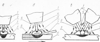
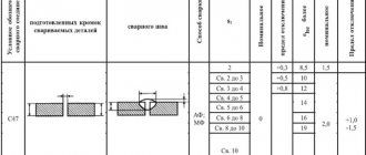
Mechanized submerged surfacing of cylindrical and flat parts is a development of manual surfacing methods using electrodes with thick, high-quality coatings. This method was developed by a team led by Academician E.O. Paton in 1938–1939 The essence of the method is that the welding arc burns between the electrode (wire) and the product under a 10...40 mm thick layer of dry granular flux with grain sizes of 0.5...3.5 mm (Fig. 1).
The flux is non-metallic granular powders, similar in composition to electrode coatings, and in general perform the same functions as coatings, namely:
- provide slag and gas protection of the weld pool and weld bead from environmental influences;
- alloy and deoxidize the deposited metal;
- promote stable arc burning due to ionization of the arc gap during the dissociation of flux components;
- the deposited metal is refined.
To carry out automatic surfacing of parts, a complex of machines, mechanisms and devices is required, which generally constitute an automatic installation. A device that ignites the arc, feeds the electrode wire as it melts, and ensures stable burning of the arc is called an automatic head for arc welding and surfacing, or an arc machine. The most important industrial value for repair and restoration surfacing are machines with a consumable metal electrode - wire or tape.
Rice. 1. Scheme of mechanized surfacing of metal under a layer of flux : 1 – current-carrying blocks; 2 – feed rollers; 3 – electrode wire; 4 – slag layer; 5 – layer of dry flux; 6 – slag crust; 7 – weld (welded metal); 8 – base metal; 9 – weld pool; 10 – electric arc
Advantages of the mechanized surfacing method
- Increased labor productivity by 6...8 times compared to manual arc surfacing.
- Reducing energy consumption by half due to higher thermal efficiency.
- High quality of the deposited metal due to reliable protection of the deposited layer from environmental influences.
- Possibility of obtaining deposited layers with a thickness of more than 2 mm.
- Less consumption of filler material as a result of eliminating losses due to spattering and reducing waste of electrode metal.
- Better working conditions for the operator due to the mechanization of the process and the absence of an open arc.
Flaws
- A large investment of heat into the material of the part, which increases the heat-affected zone and changes the results of the previous heat treatment of the part.
- After surfacing, heat treatment of the deposited layer or the entire part is required.
- Difficulties in holding a bath of molten metal on the surface of a cylindrical part (parts with a diameter of less than 50 mm are not welded).
- Reducing the fatigue strength of a part by 20...40% due to residual stresses, porosity and structural heterogeneity of the layer.
- Appears when loading flux into a hopper and sifting it after using silicate dust, which is harmful to the human body.
Submerged arc surfacing with solid metal wire
The deposited metal is alloyed by using alloyed wire, alloyed fluxes or dosed filling of alloying impurities onto the surface of the part being deposited. Sometimes the deposited metal is not subjected to alloying, and surfacing has the goal of restoring the required geometric dimensions and shape of the part.
Fused fluxes are used for automatic surfacing:
- high-silicon manganese grades AN-348A, OSN-45, AN-60;
- low-silicon manganese grades AN-10, AN-16, AN-22;
- high-silicon manganese-free grades AN-20, AN-28,48-OF-6. For surfacing high-alloy steels and alloys, low-silicon manganese and manganese-free fluxes with lower oxidizing ability are used - AN-30, 48-OF-6.
Automatic surfacing is most often used to restore cylindrical parts. Such parts are usually fused along a helical line. The axis of rotation is horizontal. This method ensures continuity of the process and high quality of work, symmetry of residual stresses with respect to the axis of the part. However, this method makes it difficult to retain flux and liquid metal in the surfacing zone.
To retain the flux, a special flux-holding device is used in the form of a specially shaped collar attachment located around the burner mouthpiece.
In order to retain the molten metal of the bath and liquid slag, the surfacing head of the machine is installed with some displacement of the end of the electrode wire from the zenith (Fig. 2).
Rice. 2. Surfacing of a cylindrical part under a layer of flux : 1 – product; 2 – hopper with flux; 3 – electrode wire; 4 – molten flux (slag); 5 – welding arc; 6 – deposited layer; 7 – slag crust
The magnitude of the displacement “e” depends on the diameter of the welded part and the parameters of the surfacing mode and is taken from 10 mm or more. The peripheral speed is selectable from 10 to 50 m/h. The smaller the electrode diameter, the lower the deposition speed should be selected. The deposition step is determined depending on the desired layer thickness, current and voltage ranging from 3 to 12 mm. The current strength for surfacing and the diameter of the electrode wire are set depending on the diameter of the part to be deposited.
Surfacing of cylindrical parts (crankshafts, crane wheels, support rollers and others) is carried out on special rotators or lathes specially adapted for this (Fig. 3).
Rice. 3. Installation UNV-3-5 for arc surfacing of bodies of revolution
Rice. 4. Welding tractor ADF-800 (a) and automatic welding machine A-1416 (b), used for surfacing parts under a layer of flux
The surfaces of flat parts are surfaced using equipment designed for welding with additional moving devices - automatic welding machines and welding tractors (Fig. 4).
The ADF-800 welding tractor is designed for welding and surfacing with electrode wire under a layer of flux. Works in conjunction with rectifiers VDU-1250, VDU-1202, VDU-630, etc. ADF800 is a self-propelled device in which the supply of welding wire, movement and protection of the arc occur automatically according to a specific program. The suspended self-propelled automatic machine A-1416 is designed for double-arc welding and surfacing with a solid wire under a layer of flux of low-carbon and alloy steels on direct current with welding speeds and electrode wire feed independent of the arc parameters. Deep regulation of the electrode wire feed speed and welding speed, obtained by replaceable gears, provides a wide range of applications for the machine.
Surfacing is carried out using separate beads along or across the surface to be deposited. It is advisable to carry out surfacing of lower but wider layers of metal with the electrode wire tilted at an angle of 40...50° to the horizon, the depth of metal penetration is two times less, the width of the deposited bead is greater under the same surfacing modes.
To obtain a wide layer, surfacing is used:
- multielectrode;
- multi-arc;
- with transverse vibrations of the electrode;
- steel tape.
Surfacing productivity is estimated in kg/h of deposited metal. For example, with manual arc surfacing, productivity is estimated in the range of 0.8...3 kg/h; automatic with one electrode – 2…15 kg/h; multi-electrode – 5…30 kg/h; electrode tape – 10…60 kg/h.
Types of metal surfacing
The surfacing technology must ensure both the quality of the deposited layer and minimal impact on the metal of the base part in order to avoid its deformation.
In addition, different surfacing methods have different processing speeds and differ in the consumption of welding materials per unit of deposited metal. Each of them is characterized by its own relationship between quality and production and economic indicators.
At the same time, in real production conditions, surfacing of parts may not be carried out in the most successful way. For example, many enterprises do not have equipment for electroslag surfacing, which saves multiple times on electricity and surfacing powders, and use electric arc methods for the same purposes.
Most surfacing technologies are focused on working with steel products, including the application of coatings of non-ferrous metals. As a rule, the following types are distinguished among them:
- electric arc;
- vibrating arc;
- gas-flame;
- plasma;
- laser;
- induction;
- electroslag;
- electrospark
A separate type of these technologies is babbitt surfacing, which is produced at temperatures of +300...+400 ºC using gas-flame heating.
Electric arc surfacing
Most often, traditional electric arc equipment is used for metal deposition. In manual arc surfacing, these are standard rectifiers and DC inverters, connected with a plus to the electrode and a minus to the part.
This switching circuit is used to reduce the depth of penetration and overall heating of the product. Metals are manually fused both with piece coated electrodes and with the help of devices with non-consumable electrodes and semi-automatic devices with a gas protective medium.
Manual electric arc surfacing with carbon electrodes using powder mixtures is used to create strengthening surface layers. In this case, to ensure stable melting of the metal in the filler powder, an inclusion with direct polarity (plus on the part) is used, which increases the heating of the surface layer of the product.
As part of mechanized surfacing equipment, semi-automatic welding machines are usually used with the supply of solid or flux-cored wire, which allows working under submerged arc.
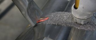
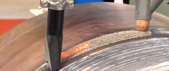
Such installations have high productivity and provide high quality deposited surfaces. The video below shows the restoration of the metal layer in the mounting hole of a mining equipment part in automatic mode.
The main process is preceded by stripping the metal using a straight grinder and heating the weld area with a gas burner. Copper-plated surfacing wire is used as a filler material.
Vibration arc surfacing using wire
Vibrating arc surfacing is used to deposit metal less than one millimeter thick with minimal heating of the top base layer.
This technology is an intermittent welding process, during which the electrode oscillates in the axial direction with a frequency of up to one hundred hertz and an amplitude of 0.3 to 3 mm.
As a result of such fluctuations, the arc lifetime is about one-fifth of the entire operating cycle and a small amount of metal is transferred to the surface. Therefore, the penetration depth is small, and the thermal effect on the main part is minimal.
Vibro-arc surfacing is carried out using semi-automatic devices equipped with special electromechanical intermittent feed devices, and a surfacing wire with a diameter of 1.6÷2 mm is used.
The fusing process is carried out in a protective environment of gas, aqueous solutions or foam.
Gas-flame surfacing
Gas-flame surfacing is considered the simplest and most affordable method of metal surfacing, in which the heat source is a flame of burning acetylene or a propane-butane mixture.
Welding wire or rods are usually used as filler material, which are fed into the welding zone manually or mechanized, and mixtures based on borax and boric acid are most often used for fluxes.
Small parts are fused without preheating, while large parts must be heated to a temperature of at least 500 ºC before surfacing.
In addition to wire and rod additives, gas-flame cladding also uses powder additives, which are directed into a gas stream from a special accumulator, melt in the flame flow and settle on the surface of the part in the form of small drops of metal.
Plasma surfacing
Plasma surfacing is performed on special welding machines called plasmatrons.
The main element of such equipment is a special burner, in which a flow of gas plasma is formed, reaching a temperature of several tens of thousands of degrees. In plasma surfacing, traditional filler materials are used, including granular mixtures, which are fed into the working area by mechanized means.
This type of surfacing technology is characterized by a small depth of penetration of the main part in combination with the high-quality structure of the deposited metal layer.
Electroslag surfacing
Electroslag surfacing is a thermal process in which the heating source of a granular filler mixture applied to the surface of a part is a slag bath.
Such a device is a small container with a crystallizer that is moved along the surface of the base part. A consumable electrode is lowered into it from above or a granular additive is supplied, while the melting of the metal occurs under a layer of slag and flux, which protects the fusion zone from the unwanted effects of atmospheric gases.
The vertical location of the slag bath promotes the floating of gas bubbles and slag particles, which helps reduce the number of pores and solid inclusions in the deposited metal.
In addition, the slag layer protects against metal splashing and retains the heat of the working area, so this technology is characterized by reduced energy consumption. Some of its few disadvantages are the increased complexity of the technological process and the inability to work with small parts and complex configurations.
Laser surfacing
Laser surfacing works on the same principle as plasma and gas flame powder surfacing.
Here, a flow of filler material is also created from powder with metal compounds and flux, only its melting is carried out using a focused laser beam. The main element of laser systems is a special head with a nozzle in which a laser-heated gas flow is formed, and a powder injector that injects additive powder into this flow.
Compared to other types of surfacing technologies, laser surfacing is characterized by high accuracy and stability of technological modes.
Induction surfacing
Induction surfacing is based on the melting of the filler material and the top layer of metal by eddy currents induced on the surface of the product using a high-frequency field.
To do this, a layer of filler material with flux is first applied to the area of the part intended for metal deposition. Then an inductor is placed above it at a short distance, which is several turns of a copper tube or busbar, to which high-frequency voltage is applied.
The depth of metal penetration of the base part depends on the frequency of the inductor current: the higher the frequency, the shallower the depth the eddy currents penetrate. This fusing method has one of the highest productivity and provides minimal heating of the metal of the product.
Electric spark surfacing
Electric spark surfacing is one of the types of electrical discharge processing based on the effect of short-term electrical discharges on the surface of a metal product.
The main elements of an electric spark installation are an electromagnetic oscillator and an electrode, from which metal particles escape during spark discharges. Since metal ions have a positive charge, the electrode is connected to the positive and the part to the negative.
Using the electric spark method, coatings with thicknesses ranging from several microns to 0.5 mm are applied. In this case, the deposited metal turns out to be dense and finely porous, which contributes to good oil retention on the friction surfaces.
One of the main advantages of this technology is the almost complete absence of heating of the treated surface, which avoids deformation of the product and changes in the structure of the metal.
Automatic submerged surfacing with electrode strip
Research by the Institute of Electric Welding named after. E.O. Paton of the National Academy of Sciences of Ukraine showed that with automatic surfacing under a layer of flux, instead of electrode wire, you can use a tape of small thickness (0.3...1.0 mm) and large width (10...100 mm or more). When surfacing with tape, a small depth of penetration of the base metal is obtained due to the low current density and at the same time reliable penetration is ensured. The share of participation of the base metal in the formation of the weld bead ranges from 5 to 15%. High productivity of the surfacing process is achieved through the use of high currents without increasing the penetration depth of the base metal and the application of a large width bead in one pass.
The minimum current density, determined by the ratio of the current strength to the cross-sectional area of the electrode strip, ensures a stable surfacing process. Typically, the current density when surfacing with tape is about 10 A/mm2, while the arc voltage is Ud = 22...36 V, the surfacing speed is from 4 to 12 m/h. Depending on the mode, a layer with a thickness of 2.5 to 8 mm can be deposited in one pass.
Electrode strips of various compositions are used for surfacing. For example, ductile iron strip can be used for wear-resistant surfacing. Using AN-28 flux and an automatic arc voltage regulator, you can obtain good bead formation with a hardness of 40...50 HRC. At the same time, the wear resistance of the deposited layer is several times greater than the wear resistance of structural steel. It is possible to obtain a deposited layer not only from cast iron, but also from various wear-resistant steels and non-ferrous metals. For corrosion-resistant coatings, strips made of steels 12Х18Н9Т, 12Х18Н10Т, YuХ18Н9Б, 10Х19Н11МЗ, 20Х13Н4Г9, 10Х13 are widely used. When using such tapes, the best results in forming a deposited layer are obtained by pumice-like flux AN-26, and when surfacing with a tape of steel 20Kh13N4G9, flux 48-OF-10. When surfacing, beads are formed that have the correct shape, and the slag crust is easily separated.
For surfacing products from non-ferrous alloys (bronze, copper), the following grades of tape are produced: BrAMts9-2, BrBNT1.9, BrKMts3-1, BrA5, BrOF6.5-0.15, BrOTs4-3, BrOTsS4-4-2.5. Fluxes are used as a protective medium, as well as protective gases - argon, helium, nitrogen and their mixtures. The best protection is argon, which provides reliable arc protection and minimal penetration of the base metal. Surfacing with BrAMts9-2 bronze tape can be carried out using AN-348A, AN-60, AN-20, AN-26 fluxes.
For surfacing parts made of nickel alloys, you can use strips of manganese nickel of the NMTs2.5 and NMTs5.0 grades or pure nickel of the NP1, NP2, NP3 and NP4 grades. Nickel tapes containing strong deoxidizers (1.5% Al and 2.0...3.5% Ti), or tapes and fluxes containing 2...3% Nb and 3% Mn are also used.
Mechanized electric arc surfacing in protective gases
In industry, various methods of electric arc welding and surfacing are used in shielding gases: argon, helium, carbon dioxide. In many cases, these methods make it possible to restore or strengthen the surfaces of products whose surfacing is difficult by other methods. In addition, gas-electric welding creates opportunities for automation of surfacing operations where the use of automatic and semi-automatic submerged arc welding is impossible. At the same time, labor productivity increases significantly and the cost of surfacing work decreases.
Developed by professors K.V. Lyubavsky and N.M. Novozhilov’s method of welding with a consumable electrode in a carbon dioxide atmosphere made it possible to obtain tight seams when welding low-carbon, low-alloy and high-alloy austenitic steels.
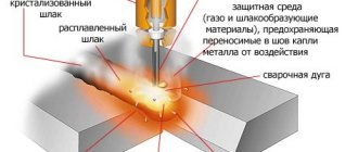
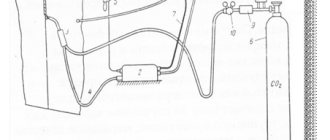
The essence of the method is that air (oxygen, hydrogen, nitrogen, water vapor, etc.) is pushed out of the welding zone by a jet of carbon dioxide, and the oxidation of the metal molten by the arc by carbon dioxide itself is compensated due to the increased content of deoxidizing elements in the electrode wire (Fig. . 5). The quality of welded joints is significantly influenced, especially in semi-automatic welding, by the welding technique.
The reliability of the gas protection of the welding zone from air, the cooling rate of the metal, the shape of the weld, and the conditions for removing gas bubbles and non-metallic inclusions from the weld pool depend on the distance, angle of inclination and nature of the movement of the torch.
Rice. 5. Scheme of surfacing in a carbon dioxide environment : 1 – mouthpiece; 2 – electrode wire; 3 – burner; 4 – tip; 5 – burner nozzle; 6 – electric arc; 7 – weld pool; 8 – weld bead; 9 – restored product
The process of repair welding and surfacing in carbon dioxide must be carried out using a short arc. When welding at currents of 200...250 A, the arc length should be in the range of 1.5...4.0 mm, since increasing the arc length increases the splashing of liquid metal and causes waste of alloying elements. Welding is possible on direct current, as well as on alternating current using an oscillator.
Automatic surfacing in a shielding gas with a consumable electrode is carried out by feeding wire from a cassette to the welding site at a constant speed through a current-carrying nozzle. Shielding gas from the cylinder is supplied through a hose through the torch nozzle to the place where the arc burns. The effectiveness of gas protection depends on the design features of the gas supply nozzle, the distance between the end of the nozzle and the surface of the part, as well as the deposition rate, shielding gas pressure and air movement at the deposition site. Surfacing in protective gas allows you to mechanize the work process in any spatial position. For surfacing in a carbon dioxide environment, carbon and low-alloy wire with a diameter of 0.8 to 3 mm is used. Wire with a diameter of 0.8...1.6 mm is used for minor wear of parts and for surfacing cylindrical parts of small diameters with any wear. The maximum thickness of the deposited single-pass layer in this case is 1…2.5 mm. The surface of the wire should be free of rust and various contaminants that lead to the formation of porosity and reduce the stability of the arc. Wire cleaning can be done either mechanically or chemically. The chemical composition of the electrode wire must be such that it is possible to sufficiently deoxidize the molten metal bath, alloy it and obtain a dense deposited metal. When surfacing carbon and low-alloy steels, silicon and manganese are used as deoxidizing agents.
For surfacing steel and cast iron products in a carbon dioxide environment, wire grades Sv-12GS, Sv-08G2S, Sv-Kh13, Sv-Kh17, Sv-06Kh19NT, Sv-18KhMA, Sv-08Kh20N9G7T are used.
For welding in CO2, flux-cored wire of the PP-18T, PP-4Kh2V8T, PP-Kh12VFT brands is also used.
The use of wire grades Sv-12GS, Sv-08GS, Sv-08G2S for surfacing produces a deposited metal that is not very hard and wear-resistant. Such wires are used mainly to restore the geometric parameters of a product.
During surfacing operations there is no need to obtain deep penetration of the base metal. Therefore, the main factors are: stable arc burning, productivity and quality of surfacing work. From the point of view of process stability, it is recommended to take the current strength depending on the wire diameter according to the following data:
| diameter (mm) | 0,8; | 1,0; | 1,2; | 1,6; | 2,0; | 2,5; |
| current (A) | 60…120 | 80…160 | 90…260 | 120…350 | 200…450 | 250…550. |
The decrease in current should correspond to a decrease in the electrode wire feed speed.
An increase in arc voltage leads to an increase in the width of the deposited metal bead, an increase in metal losses due to spattering, waste and oxidation, the quality of the deposit deteriorates, and pores appear. Therefore, it is recommended to withstand a certain arc voltage depending on the current strength:
| current (A): | 60 | 100 | 140 | 200 | 250 | 300 | 400; |
| voltage (V): | 18 | 19 | 20 | 22 | 25 | 28 | 30. |
Carbon dioxide surfacing has especially great advantages over submerged arc surfacing when restoring cylindrical parts of small diameters (10...20 mm).
Electrode wire stickout has a significant impact on the stability of the surfacing process. A large overhang causes excessive heating and burnout of the wire at the point of contact with the current-carrying device. The higher the current density, the smaller the electrode stickout should be.
When surfacing in a CO2 environment, the beads should overlap each other by 1/3 of the width, which gives a more even surface of the deposited metal.
Surfacing of steels with a high carbon content or alloying impurities must be done with preheating of the part and with higher heating of carbon dioxide. Otherwise, hardening of the metal in the heat-affected zone is possible, which leads to the appearance of microcracks and impairs the machinability of the metal with a cutting tool.
For welding with a consumable electrode in a carbon dioxide environment, semi-automatic and automatic machines of both Russian and foreign production are used.
Rice. 2. Scheme of combining vibro-arc surfacing with thermomechanical processing: 1 - deforming roller; 2—mouthpiece; 3 - detail; 4 - supporting rollers.
For submerged surfacing of parts, semi-automatic and automatic surfacing heads of various designs are produced (PSh-5, PSh-54, PDShM-500, ABS, A-580M, A-874N, A-384MK, ADS-1000-4). The main parts of the surfacing head are a wire-pulling mechanism with a device for stepwise or smooth change of wire feed speed during automatic submerged arc welding: a - longitudinal section through the weld pool; b - diagram of the interaction between metal - slag - gas.
Rice. 3. General scheme of interaction of metal with gases and slag
Rice. 4. Installation diagram for automatic surfacing of cylindrical parts under a layer of flux: 1 - gearbox; 2 - electric motor; 3 — counter drive; 4 — welding converter; 5 — hardware box; 6 — lathe chuck; 7—deposited part; 8 - holder; 9 - bunker; 10—wire feeding mechanism; 11 - cleaner; 12 — cassette with wire.
The installation diagram for automatic surfacing is shown in Fig. 4. The surfacing head is mounted on the support of a lathe, equipped with a gearbox to change the speed of the part from 0.25 to 4 min”-1. Current flows to the workpiece through copper-graphite brushes and a ring-shaped copper busbar mounted on the machine chuck. The metal is deposited by longitudinal movement of the caliper with the surfacing head. The power sources used are rectifiers VDG-301, VDU-301UE, VDU-504, VDU-1001, VS-600, VSS-400, VKSM-500, VKSM-1000, DC welding generators (PSO 300/500, PSU- 300/500, PSG 300/500).
However, when surfacing on such installations, the flux gets onto the machine bed and causes its rapid wear; suction of unmelted flux is difficult; the possibilities of surfacing products with complex configurations are limited, etc.
The Maloyaroslavets branch of GOSNITI and TsOKTB have developed machines for restoring worn surfaces of parts such as “rotation bodies” of tractors, cars and agricultural machines:
1) SZhS-11200-GOSNITI - for wide-layer surfacing of the surfaces of the running tracks of support and support rollers of caterpillar tractors with flux-cored wire PPAN-122, PPAN-125, 0 2.6...3.2 mm or solid wire Ni-ZOKHGSA, Sv-08, 0 2... 3 mm under fluxes ANK-18, AN-348A for hardness up to 56 HRC3. The diameter of the welded rollers is 180… 240 mm. Capacity 40…50 rollers per shift. Source! arc supply - rectifier VKSM-1000-1 - 1. Overall dimensions 2230X 1146X2360 mm.
2) OKS-11236-GOSNITI - for surfacing the surfaces of flanges and support rollers, guides and tension wheels of caterpillar tractors with flux-cored wire and solid wire submerged. The brands of electrode material and fluxes are the same. The diameter of the welded rollers is 270…790 mm. Capacity 25…30 rollers per shift. The arc power source is a welding rectifier VS-600. Overall dimensions of the machine are 2130X930X1860 mm.
Institute of Electric Welding named after. E. O. Paton developed a series of specialized surfacing machines U-425, U-427, U-441, U-470 for surfacing individual parts with solid electrode wire and tape.
In addition, general-purpose machines with an oscillating electrode have been developed: U-651 (for open-arc surfacing of worn surfaces and splines of parts with a diameter of 20-M 50 mm and a length of 1300 mm. Electrode wire with a diameter of 1 ... 2 mm or flux-cored wire with a diameter of 2 ... is used. 3 mm); U-652 (for restoration by submerged surfacing of crankshafts with a journal diameter of up to 100 mm and a shaft length of up to 1300 mm with solid (1...2 mm) or flux-cored wire with a diameter of 2...2.5 mm); U-653 and U-654 (for submerged surfacing and flux-cored wire surfacing of external, internal, cylindrical, conical and spline surfaces of parts with a diameter of 50 to 800 mm and a length of up to 1300 mm). Transverse vibration of the electrode makes it possible to increase labor productivity and improve the quality of surfacing.
Purpose of fluxes. Fluxes used in surfacing have the following purposes: they create the possibility of using a current of greater density than in manual welding; protect the welding zone from exposure to oxygen and nitrogen in the air and reduce spattering and waste of metal; slow down the process of metal hardening, creating favorable conditions for gases to escape from the seam; reduce heat loss from the welding arc due to radiation and heating of ambient air flows; create good conditions for the formation of a fine-grained weld structure and ensure stability of the welding process.
In addition, many of the fluxes used provide alloying of the weld, for example, with silicon, chromium, manganese and other elements, which increases the wear resistance of the restored part. Compared to manual welding, the productivity of automatic submerged cladding increases by more than 7 times.
High productivity, good bead formation and high quality of deposited metal are the main advantages of this method. The disadvantages are: the need and difficulty of removing the slag crust, the formation of a large amount of dust, a large heat-affected zone, the impossibility of surfacing parts with a diameter of less than 45 mm, a decrease in fatigue strength to 20...40%.
According to the production method, fluxes are divided into fused (AN-348A, AN-20, AN-28, AN-60, OSTS-45) and unfused ceramic (ANK-18, K-2, KS-1, ZhSN-1, E -29). The former are obtained by fusing the components of the charge in electric or flame furnaces, followed by grinding them to a certain granulation. They ensure stability (uniformity) of the chemical composition of the deposited metal. The main disadvantage of these fluxes is their weak deoxidizing effect. Fused fluxes can only slightly alloy the deposited metal with manganese and silicon, increasing their content to 0.15...0.20% due to silicon and manganese reduction processes.
Unfused (ceramic) fluxes are made from a mixture of powdered materials held together primarily by liquid glass. They allow you to alloy the deposited metal with any elements. However, chemical heterogeneity increases to 10...15% due to the greater difference in the concentration of carbon and carbide-forming elements between the deposited and base metals. Ferrochrome, ferromanganese, ferrosilicon, ferrotitanium are introduced into their composition as alloying components, and marble, limestone, fluorspar, quartz, and titanium dioxide are used to form slags. In this case, individual alloying elements play the role of both alloying and deoxidizing elements.
The use of ceramic fluxes is promising for the restoration of many machine parts with high wear (track rollers, idler wheels, their axles, frame axles), since the presence in their composition, in addition to slag-forming components, alloying, deoxidizing and modifying substances allows the use of non-deficient low-carbon wire to obtain high-quality metal with the necessary service properties.
Mixed fluxes are widely used when restoring parts, that is, when alloying elements are added to the fused standard flux AN-348A.
To obtain hard and wear-resistant coatings, the following alloying materials are used: silver graphite from electrodes for steel-smelting furnaces and fine gray “Taiginsky”; ferromanganese containing 70...80% manganese and 1.5...2.0% carbon; ferrosilicon containing 70...80% silicon; ferrochrome XP-800, containing 70...80% chromium and 7...8% carbon; aluminum powder.
The advantage of ceramic fluxes and flux mixtures is that their use in surfacing provides a hardening structure, and therefore high hardness (without subsequent heat treatment) due to the introduction of a high content of chromium and carbon into the coating. In this case, chromium significantly reduces the critical hardening rate, and the presence of carbon ensures self-hardening of the deposited metal during its natural cooling.
The disadvantages of these fluxes include the fact that when they are used in the deposited metal, there is an uneven distribution of alloying elements and structural heterogeneity, leading to “spotty” hardness of the coating.
Electrode materials. Solid wires with a diameter of 1.2...2.5 mm are used as electrode materials. For surfacing low-carbon and some low-alloy steels, low-carbon (Sv-08, Sv-08A, Sv-15), manganese (Sv-08G, Sv-08GA, Sv-15G, Sv-10G2) and silicon-manganese (Sv-10GS) wires are used. steels For surfacing alloyed and high-alloy steels, wire made from alloyed and high-alloy steels is used (Np-18KhGSA, Np-ZOKHGSA, Sv-08Kh14, Sv-2Kh13, Np-65G).
The use of flux in arc surfacing entails a number of technological difficulties and complicates the mechanization and automation of the process.
In the case of using flux-cored wire or tape, it is possible, by changing the composition of the filler, to abandon flux and protective gases, since the gases and slag formed during the surfacing of powdered components of the wire or tape charge can protect the liquid metal from exposure to the atmosphere and increase the stability of the surfacing process. Flux-cored wire (FC) is made from a low-carbon steel strip rolled into a tube, inside which a charge is placed - a powdered core consisting of a mixture of ferroalloys (ferrotungsten, ferrochrome, ferromanganese, ferrovanadium), iron powder, graphite and other materials.
The core of flux-cored wires for submerged arc surfacing contains predominantly alloying elements, and for open arc surfacing it contains materials that form gases and slags, which reliably protect against oxygen and nitrogen in the air. The advantage of cored wires with internal protection is that their use does not require the use of protective gases, fluxes or other means. It becomes possible to alloy the deposited metal layer over a wide range.
At the same time, the deposited metal contains a large number of alloying elements that ensure its self-hardening in air.
The use of flux-cored wires allows saving surfacing material.
Flux-cored wires are recommended for the restoration of parts with large amounts of wear, medium and high hardness - HB 200...600, especially those operating under conditions of intense wear: road wheels, axles, cranked axles, tractor transmission shafts, etc.
Currently, steel strips made from various grades of steel are used for submerged surfacing: tool steel, spring steel, stainless steel and heat-resistant alloys. The tape is supplied in rolls. For surfacing, a tape with a thickness of 0.1 ... 0.3 mm and a width of 20 ... 50 mm or a special flux-cored tape PL-AN102, PL-A171, etc. is usually used.
Work is underway on the use of cermet strips for mechanized surfacing, which are produced by cold rolling of powders followed by sintering in a protective environment (tapes LM-70KhZMN, LM-5KhV4VFS, etc.).
The use of flux-cored wires and tapes makes it possible to obtain a deposited layer of the required composition and quality and save electrode materials.
The grade of electrode material and flux is selected taking into account the required physical and mechanical properties of the deposited metal of the part being restored.
Justification for the choice of submerged arc surfacing mode. The submerged surfacing mode (including the grade of flux and filler material) includes the parameters of the electric current, the surfacing speed, the wire feed speed, its diameter and position relative to the surface being deposited, and the surfacing pitch.
Welding current determines the depth of penetration of the base metal and the productivity of the process. With increasing current (at a constant deposition rate and voltage), the volume of the liquid bath, the depth and area of metal penetration increase, which leads to an increase in the height of the deposited bead. However, with a further increase in current, the formation of the weld bead deteriorates; there is no smooth transition from the surface of the deposited metal to the base metal. There is a danger of deformation of the part, the concentration of alloying elements in the deposited layer decreases, and the proportion of the base metal in it increases. The smaller the diameter of the part, the smaller the current and diameter of the electrode wire should be. The current is selected depending on the diameter of the electrode wire and is regulated by its feed speed. Arc voltage is related to the amount of welding current. The greater the current, the higher the arc voltage should be.
With increasing arc voltage (at a constant current and speed of movement), the width of the deposited bead increases, and the amount of molten flux increases, i.e., consumption. With a low arc voltage, a high and narrow bead is obtained, with a high arc voltage, a low and wide bead is obtained.
In addition, as the voltage increases, arc stability deteriorates. For surfacing parts, the recommended voltage is within 26...36 V. The range of optimal modes for submerged surfacing during alloying is shown in Fig. 2.5.
The deposition rate also has a significant influence on the formation of the weld bead. With an increase in the deposition rate, the width of the deposited bead decreases and the depth of penetration decreases slightly. The deposition rate is limited by the size of the weld pool and the rate of its crystallization. Typically, the deposition speed is selected at 15...45 m/h.
The electrode extension is selected to provide the greatest melting of the electrode, less than the base metal, and sufficient flux melting to protect the molten metal pool. When using surfacing wire with a diameter of 1.2...1.5 and 1.6...2.0 mm, the electrode extension is recommended to be 10...20 and 20...25 mm, respectively, and for steel strip - 30...35 mm.
The electrode is shifted from the zenith when surfacing cylindrical surfaces in the direction opposite to the direction of rotation by an amount equal to 10% of the diameter of the part being deposited, or it is set experimentally: the molten metal and flux, being in a horizontal position, must have time to harden and not flow down the cylindrical surface.
Rice. 4. Selection of submerged arc surfacing mode during alloying:
The inclination of the electrode, in turn, affects the cross-sectional shape of the weld bead. The process proceeds normally and leads to the formation of a correctly formed weld bead only if the electrode is inclined at an angle of 6...8° to the axis of the bead in the direction of welding. With a further increase in the angle of inclination, lack of penetration appears along the edges of the roller.
The surfacing pitch is determined by the diameter of the part being deposited, the current strength, the diameter of the wire, etc. With circular surfacing, the pitch is set so that each subsequent bead overlaps the previous one by approximately 1/2...1/3 of the width. Speed, deposition step and other parameters are set according to the dimensions of the part.
The optimal modes for surfacing with electrode strips are: welding current density (not lower than 15 A/mm2); arc voltage (not less than 25 V and not higher than 35...37 V); surfacing speed (8...20 m/h); electrode extension (30...35 mm); direct current of reverse polarity. The most suitable flux for surfacing with electrode strips is AN-60.
When surfacing with electrode tapes, automatic surfacing heads OKS-1252M, A-384MK, ABS, A-874N, ADS-1000-2, ADS-1000-4 and current sources VDU-504, VKSM-1000, PSO-500 can be used as surfacing heads. etc. Surfacing machines must be equipped with a special attachment for feeding electrode strip.
The advantages of this method are high productivity, small penetration depth, the ability to widely adjust the width of the roller (up to 50 mm or more) and change the chemical composition (powder belts). In addition, surfacing with electrode tape allows you to increase the welding current without significantly increasing the depth of penetration of the base metal.
The disadvantages are the difficulty of surfacing parts with small diameters, as well as the small permissible tilts of the part (5...7°) in the transverse and longitudinal directions and the difficulty of exciting the arc.
The sequence of establishing submerged surfacing modes: thickness of the deposited layer, diameter of the electrode wire, current value, arc voltage, electrode feed speed, surfacing speed and pitch, electrode wire stickout, thickness of the flux layer, grade of electrode wire and flux.
A large number of variable parameters characterizing the surfacing mode makes it difficult to control the automatic surfacing process. Therefore, optimization of these parameters, and primarily the parameters of current and deposition rate, which determine the thermal regime of welding, is especially important in the issue of restoration of parts by surfacing.
The constancy of the chemical composition and structural homogeneity of the deposited metal, the size and shape of the deposited beads, the depth of penetration and the quality of fusion of the metals being joined, and the depth of heating of the base metal (heat-affected zone) significantly depend on the thermal regime of surfacing. The penetration depth must be minimal and at the same time sufficient to ensure that a reliable connection is achieved between the deposited and base metals.
An increase in the thermally affected zone and heating temperature leads to a change in the structure of the base metal. This is of particular importance when surfacing parts made of high-carbon and chromium steels, which are prone to hardening. When heated followed by rapid cooling in the heat-affected zone, hardness and brittleness sharply increase, sometimes accompanied by the appearance of cracks. The latter, along with residual stresses, structural heterogeneity, and porosity, is one of the reasons for the decrease in fatigue strength of parts restored by submerged arc surfacing.
When restoring automobile and tractor parts, the recommended ranges for changing the heat input of the welding arc are within the range of 630... 1890 kJ/m.
As can be seen, the same values of arc energy input, and therefore the physical and mechanical characteristics of coatings and parts restored by surfacing, can be obtained not with one value of the mode parameters, but in a wide range of changes in one of the parameters with a corresponding change in the other two.
We have analyzed the recommended modes of submerged surfacing (including surfacing with electrode tape). The results of the analysis show that, despite significant differences in the values of the main parameters of the mode (current value, voltage, deposition rate), the value of the arc energy input is in the range of 630...1890 kJ/m.
To obtain high-quality coatings, the heat input of the arc should be in the range of 630... 1590 kJ/m. The larger the diameter of the electrode wire and the dimensions of the part, the larger the value of W should be taken. The choice of surfacing mode parameters based on the value of W is very important.
Semi-automatic machines for surfacing in shielding gases
Semi-automatic PDG-603 (Fig. 6, a) is intended for mechanized arc welding and surfacing in a shielding gas environment, as well as self-shielding flux-cored wire of products made of low-carbon and structural steels. The semi-automatic machine has smooth control of welding parameters, the setting of three independent welding modes, a feed attachment with four
driving gear rollers, a remote control panel, as well as water cooling of the torch when welding at maximum conditions.
Rice. 6. Semi-automatic machines for arc welding and surfacing in shielding gases : a – semi-automatic PDG-603; b – semi-automatic “Midicom-160”
The semi-automatic machine PDGO-501-1 is designed for semi-automatic welding and surfacing of metal with a consumable electrode both in a protective gas environment and with flux-cored wire. The wire feed speed is adjustable in steps from 95 to 725 m/h, wire diameter is 1.2...3.2 mm. The semi-automatic machine is placed on a light trolley along with a device on which a coil of electrode wire weighing up to 80 kg can be placed. The semi-automatic welding kit may include:
- power supply VDG-506 with arc voltage regulation from 18 to 50 V;
- torch for current up to 300 A for welding in a shielding gas environment;
- torch with a current of up to 500 A for welding with flux-cored wire;
- welding wires and control cable with a range of 10 m. Semi-automatic “Midicom-160”. , Russia. Small-sized semi-automatic welding “Midicom-160” (Fig. 6, b) is designed for manual arc welding on direct current with a consumable electrode in a shielding gas environment
low-carbon, alloy, and stainless steel with a total thickness of up to 4 mm. Can be used to perform a variety of welding and installation work in car repair and construction. The semi-automatic device consists of a power transformer, a rectifier and an LC filter of welding current, an electrode wire feeder with a reel and a flexible working hose, a shielding gas supply device, an electronic control unit, a selection of operating modes and indications, and a forced cooling system.
The semi-automatic MIG 305 C/S is used for welding metals of any thickness and chemical composition with solid or flux-cored wire in shielding gases.
Technical characteristics of the semi-automatic device
- Current 40…300 A
- Mains voltage 3380 V
- Current at duty cycle = 35% 285 A
- Current at duty cycle = 60% 215 A
- Current at duty cycle = 100% 170 A
- Open circuit voltage 16…47 V
- Number of voltage adjustment stages 20
- Weight 130 kg
The most favorable conditions for the formation of a metal bead are observed during surfacing in inert monatomic gases argon and helium (Fig. 7). In argon, there are two types of metal transfer through the arc: large-droplet transfer without short circuits with slight spattering at a subcritical current and jet transfer at a current greater than the critical value. The type of metal transfer through the arc gap affects the form of penetration of the base metal and the formation of the deposited bead. Surfacing with jet transfer of electrode metal is undesirable, since this significantly increases the depth of penetration of the base metal.
In helium, droplet transfer is observed with short circuits of the arc (low current and voltage) and without short circuits at increased current and voltage with slight spattering of the electrode metal.
Rice. 7. Scheme of the surfacing process with electrode wire in an argon environment : 1 – welded product; 2 – burner; 3 – electrode wire; 4 – shielding gas; 5 – gas nozzle; 6 – welding arc; 7 – weld pool; 8 – weld bead; 9 – protective atmosphere
A bead of metal deposited in a helium environment has less convexity than in argon, since argon increases the surface tension of the liquid metal. The use of an Ar+He mixture allows you to take advantage of the advantages of both gases.
Surfacing with flux-cored wire and flux-cored strip
A very promising method for restoring and strengthening the surfaces of parts, which can significantly increase labor productivity compared not only with manual but also mechanized welding in carbon dioxide, is welding and surfacing with flux-cored wire. Its distinctive feature compared to other mechanized methods is that it combines the advantages of both manual welding - simplicity and mobility, and mechanized welding in carbon dioxide - greater productivity and high quality of welded joints.
The use of flux-cored wire for surfacing operations allows one to significantly expand the range of welded steels, since for most of them it is impossible to obtain the corresponding monolithic alloyed wire metallurgically.
The idea of using electrodes with a strong conductive shell and a less durable “core”, the composition of which can be changed, was put forward in the 19th century by the great Russian inventor N.N. Benardos, the founder of electric arc welding. In the 30s, for the first time in the history of welding technology, Soviet engineer V.E. Sakhnovich experimentally proved the possibility of using electrodes consisting of a thin-walled steel tube and a welding flux core for automatic open arc welding, i.e., without external protection with carbon dioxide or flux. He used electrodes made from seamless steel tubes into which powdered dry flux was poured; the ends of the tubes were welded, and they were crimped by 1.5...2.0 mm in order to compact the charge. They were named V.E. Sakhnovich “electrodes with internal coating”. In the early 60s, at the Electric Welding Institute named after. E.O. Paton proposed a tubular electrode wire, called “cored wire for welding”. Flux-cored wire welding is constantly being improved, and this mechanized arc welding method is increasingly used both in our country and abroad.
Automatic and semi-automatic surfacing with flux-cored wire
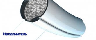
Flux-cored wires are tubular wires with a complex internal cross-section filled with powdery filler (Fig. 8). The filler has a composition suitable for welding electrode coatings. The mass of powdered filler ranges from 15 to 40% of the weight of the wire.
The powder included in the flux-cored wire, when melted by an electric arc, performs the following functions:
- provides gas and slag protection of the weld pool from environmental influences;
- promotes deoxidation of the weld pool;
- alloys the weld;
- stabilizes the arc discharge.
Rice. 8. Flux-cored wires for welding and surfacing : a – appearance; b – wire sections
According to the method of protection, flux-cored wires are divided into self-shielding and those used with additional protection with gas (CO2) or flux. Self-shielding wires, as a rule, are used both for the production of welded structures and for surfacing parts. Flux-cored wires, used with additional protection, are mainly used for surfacing work.
Surfacing with flux-cored wire with internal protection is based on introducing into the wire core, in addition to alloying components, also slag-forming and gas-forming materials. The use of flux and gas protection when surfacing with such wire is not required. The alloying elements of the flux-cored wire pass into the seam, and gas and slag-forming materials protect the metal from nitrogen and atmospheric oxygen. In the arc, a thin film of molten slag covers the droplets of liquid metal and insulates them from the air. The decomposition of gas-forming materials creates a flow of protective gas. After solidification, a thin slag crust forms on the surface of the weld bead, which may not be removed when applying subsequent layers. When surfacing, various self-protecting flux-cored wires are used. For surfacing low-carbon layers, welding wires of the PP-AN3 type and others are used. For surfacing parts operating at high pressures and elevated temperatures, flux-cored wire PP-3ХВ3Ф-О is used (the letter “O” in the designation of the grade of flux-cored wire indicates that this flux-cored wire designed for open arc surfacing). Surfacing of parts subject to intense abrasive wear is carried out using self-shielding flux-cored wire PP-U15X12M-O. Flux-cored wires have been developed for correcting (welding) defects in steel castings (PPs-TMV6, PPs-TMV29, PPs-TMV14, PPs-TMV15, VELTEC-N210, VELTEC-N215).
The technology for surfacing with self-shielding flux-cored wire is basically no different from the technology for surfacing in carbon dioxide. An open arc makes it possible to accurately guide the electrode and observe the process of formation of the deposited layer, which is of great importance when surfacing parts of complex shapes.
The advantages of this method: the use of less complex equipment compared to the equipment used for submerged arc surfacing and shielding gas, as well as the ability to perform surfacing work in the open air; productivity increases compared to submerged surfacing and shielding gases, and the cost of surfacing is reduced. Flux-cored wire makes it possible to use alloying substances more economically, and therefore is very promising. Recommended grades of flux-cored wire for surfacing various parts are given in the appendix. 2.
Typically, flux-cored wires are used for semi-automatic hose welding. Due to the possibility of observing the formation of a seam, the technique of surfacing various products is practically no different from the technique of surfacing them in shielding gases with a consumable electrode. When multilayer welding or surfacing with flux-cored wire, the surface of the previous layers should be thoroughly cleaned of slag.
Surfacing with flux-cored wires has its disadvantages. The low rigidity of the tubular structure of flux-cored wire requires the use of feed mechanisms with limited wire compression force in the feed rollers. Surfacing can be carried out only in the lower and rarely in the vertical position. This is explained by the fact that the resulting weld pool of increased volume, covered with liquid-flowing slag, is not held in the vertical and overhead positions by the force of surface tension and arc pressure. A significant disadvantage of flux-cored wires, which hinders their widespread industrial use, is the increased likelihood of pores forming in welds, caused by the presence of voids in the wire. In addition, unmelted components of the core, passing into the weld pool, contribute to the appearance of gaseous products. Moisture that gets into the filler during storage of the wire, as well as grease and rust, traces of which are on the metal sheath, also increases the likelihood of pore formation.
For automatic surfacing of parts with flux-cored wire, surfacing installations UD-209, UD-609, UNP-350-1, etc. are used. Typically, such installations include a manipulator-rotator based on a lathe, an arc power source, a welding head with a wire feed mechanism, control panel, protective gas cylinder. A schematic diagram of such installations is shown in Fig. 9.
Rice. 9. Diagram of a typical installation for automatic surfacing of cylindrical parts with flux-cored wire : 1 – part to be welded; 2 – manipulator-rotator; 3 – welding head; 4 – power supply; 5 – control panel; 6 – tailstock; 7 – protective gas cylinder
Powder surfacing strips
Powdered tapes are produced on special mills equipped with rollers for forming and rolling the casing tape. The mill has a metering device for feeding the charge and a cage of rolls for compacting this charge, forming a core of powder strip. The drawing process, in contrast to the production of all-metal tape, is absent in the production of flux-cored tape. The tape is usually made with a width of 40...50 mm. Powder-cored tapes are used for surfacing products made of various structural alloys, but mainly steel or cast iron. When surfacing with flux-cored strips, fluxes or shielding gases can be used as a protective medium. Some tapes can be used without additional protection. For example, flux-cored tapes PL-AN101 and PL-AN102 are universal. They are designed for both submerged arc and open arc surfacing. Basically, flux-cored belts are used in cases where the size of the worn surface is quite large and the degree of wear is small. For example, flux-cored tapes PL-U40Kh38G3RTYU and PLU30Kh30G3TYU are used for submerged surfacing of parts of construction and road machines operating under conditions of abrasive wear: the first - in the absence of impacts, the second - for parts experiencing abrasive wear with shock loads.
102
Construction machinery and equipment
Automatic electric arc surfacing under a layer of flux is one of the main methods for restoring worn parts used in enterprises repairing transport construction machines. This surfacing method was developed by the Institute of Electric Welding named after. E. O. Paton.The essence of the method: an electric arc burns between the electrode wire and the welded part under the protection of flux. The process proceeds as follows. Electrode wire or tape is automatically fed continuously and evenly into the arc burning zone. Under the influence of the arc temperature (6000-7000 ° C), part of the flux melts and a slag layer is created on the surface of the metal, protecting the molten metal from the harmful effects of air.
Rice. 20.2. Scheme of the surfacing process under a layer of flux:
1 - electrode wire; 2—slag crust; 3—gas bubble; 4— flux; 5—liquid bath; 6—welding arc; 7—welded part.
The presence of a protective layer promotes slow cooling of the deposited metal, which has a positive effect on the formation of the surfacing layer, reduces porosity and makes it difficult to harden the surface.
The quality and mechanical properties of the deposited layer are greatly influenced by the material of the wire and its diameter, the composition of the flux and the dimensions of its constituent elements (granulation), wire feed and surfacing speeds, the type and polarity of the current, surfacing modes, the selected surfacing technique and the location of the electrode in relation to welded surface.
Cylindrical surfaces are deposited along a helical line with the previous roller overlapping the next one by 1/2 - 1/3 of the width. The electrode extension is assumed to be 20-30 mm for wire with a diameter of 2-3 mm. With thicker wire the overhang increases. The arc voltage is 25-30 V. The current strength depends on the diameter of the part, the amount of wear and the diameter of the wire. The wire diameter is selected taking into account the thickness of the surfacing layer and the diameter of the part. To restore parts, wire with a diameter of 1.5-3 mm is usually used.
Welding or surfacing wire is available in diameters from 0.3 to 8 mm. The wire can be carbon and alloyed. It is marked taking into account its purpose, chemical composition and diameter. For example, low-carbon welding wire with a diameter of 3 mm and a carbon content of up to 0.1% is designated ZSV0.8; Alloyed surfacing wire with a diameter of 4 mm with a carbon content of 0.35–0.45% and manganese 0.7–1.0% is designated 4Np-40G. Electrode surfacing tape (designated LS) is available in widths from 30 to 100 mm for both single-layer surfacing (with the letter A) and multi-layer.
Fluxes used for automatic and semi-automatic surfacing can be fused manganese (AN-348 A, OSTS-45) and ceramic (ANK-18, ANK-19).
For surfacing under a layer of flux, you must have the following equipment: an automatic surfacing head, a welding current power source, equipment for controlling and regulating the surfacing process, mechanical equipment for installing and moving the part, fastening and moving the head, as well as auxiliary equipment (flux hopper, etc. ).
The main elements of the welding process are automated - feeding the wire to the arc, maintaining a constant arc gap and moving the arc along the welded seam.
Rice. 20.3. Schemes for applying beads during surfacing:
a - correct; b - incorrect.
Any welding head can be used for surfacing, but it is better to use special surfacing heads. The most common surfacing heads are A-580M, A-384MK, A-874N. These are universal devices that allow you to work on both direct and alternating current. Surfacing machine A-874N can be used to restore cylindrical and flat parts both under a submerged arc and in a carbon dioxide environment and an open arc using solid or flux-cored wire or tape. The device has a mechanism for transverse oscillation of the electrode, which allows for wide-layer surfacing.
The power source is conventional welding converters PSO and PS or selenium rectifiers. Old lathes are usually used as mechanical equipment. The part is installed in the centers of the machine, the head and auxiliary equipment are mounted on the support. To reduce the rotation speed of the machine, a reduction gear is installed. The diagram shows the operation of a surfacing installation: electrode wire 4 is fed by an automatic surfacing head 3 through a mouthpiece 5 to the welded part 7, which rotates. At the same time, flux is supplied to the arc zone from hopper 6.
Automatic surfacing under a layer of flux, compared to the manual method, increases productivity several times due to an increase in the speed of surfacing and improves the quality of surfacing: the weld is uniform and dense, alloying additives are preserved, the quality of surfacing does not depend on the individual skills of the welder; reduces material consumption; almost completely eliminates electrode wire losses; eliminates the production of coated electrodes; allows you to use flux 2-3 times; reduces energy consumption as a result of eliminating unproductive heating of the base metal, radiation and losses due to splashing and waste, which occur with the manual method; reduces the costs associated with mechanical processing after surfacing, since due to the uniform thickness of the deposited layer, the allowance for subsequent processing is reduced; improves the working conditions of welders, since there is no powerful light flux accompanying manual welding, and the emission of harmful gases is reduced.
Rice. 20.4. Installation diagram for automatic surfacing under a layer of flux:
1 - selenium rectifier; 2 — control panel; 3 — automatic head; 4 - electrode wire; 5—mouthpiece; 6—hopper; 7 - welded part; 8 - inductance regulator.
In semi-automatic surfacing under a flux layer, only the wire feeding and maintaining a constant arc gap are mechanized. For this method, semiautomatic hose welding machines PSh-5, PSh-54, PDShM-500 are used. Converters are used as a power source.
To increase productivity, two- and multi-electrode surfacing under a layer of flux is used. Multi-electrode surfacing is based on the use of the “running” arc phenomenon and consists in the fact that a special surfacing head feeds several electrode wires into the arc zone simultaneously at the same speed. When surfacing with six electrodes with a diameter of 3 mm, a weld with a width of up to 70 mm and a thickness of 3-4 mm is deposited in one pass. Despite the high welding current (up to 800 A), the penetration depth is only 1.5-2 mm. This method has high productivity and allows you to reduce the specific energy consumption per 1 kg of deposited metal by 15-20%.
Methods of automatic surfacing under a flux layer also include surfacing with flux-cored wire, strip and plate electrodes.
The essence of surfacing with flux-cored wire is that the molten metal is protected from the influence of air and is alloyed with alloying elements located inside the wire. Flux-cored wire is a metal sheath 0.5-1 mm thick, densely filled with charge. Powdered alloying and fluxing elements are used as a charge - fine cast iron shavings, blast furnace ferromanganese, ferrochrome, silver graphite, etc. Surfacing with flux-cored wire has greater hardness and high wear resistance. Therefore, it is used in the repair of parts of construction machines subject to abrasive wear and shock loads (teeth and cutting edges of excavator buckets, blades of bulldozers, motor graders, scrapers, etc.). Parts with flux-cored wire are fused using the same machines as with conventional electrode wire. There are also special devices A-765, A-1030, etc.
The current sources are PSG welding converters and BC rectifiers with a rigid electrical characteristic.
You can fuse parts with a strip electrode using flux or powder strip. In the first case, a low-carbon steel strip serves as the electrode, and flux is applied to the part. In the second case, the electrode consists of two tapes that make up the shell and a powdery charge located inside the shell. One of the tapes has cells that protect the charge from moving.
Surfacing with a strip electrode is highly productive (up to 25 kg/h), allowing you to create a layer up to 100 mm wide and 2-8 mm thick in one pass. As with multi-electrode surfacing, the welding arc moves continuously, which ensures uniform melting of the electrode over the entire cross-section. To work with a strip electrode, special attachments have been developed for surfacing machines A-384 and others. This method is used to deposit parts with high wear, for example, crawler rollers, track links, tension and drive wheels, working parts of earth-moving machines, etc.
This method also includes surfacing with a plate electrode, which consists of the following. The surface of the deposited flat part is covered with a uniform layer of flux 3–5 mm thick and a plate electrode (sheet steel 0.4–1 mm thick or roofing steel) is placed on it according to the size of the surface to be deposited. The top of the electrode is covered with a layer of flux 10-15 mm thick and covered with a copper bar. To initiate the arc, small steel shavings are poured into the place where it burns. The arc burns between the part and the electrode. From the moment the arc is excited, surfacing continues automatically.
Features of automatic vibration-arc surfacing: the electrode simultaneously with the translational movement vibrates with a given frequency and amplitude, so the arc burning process is periodically interrupted. Liquid is supplied to the contact area between the electrode and the part, which cools the part and ionizes the arc.
The diagram shows the operation of the surfacing installation. The welding wire 4 from the cassette 6 is directed by the feeding mechanism 5 through the mouthpiece which rotates in the centers 2 to the welded part 1 of the lathe. The wire mouthpiece makes oscillatory movements under the action of vibrator 7. At the same time, coolant (a solution of soda ash with the addition of 0.5% mineral oil or a 15% aqueous solution of glycerin) is supplied to the part through hose 3 through the mouthpiece by a pump. The waste liquid is collected in a special tank.
Fig.20.5. Installation diagram for vibro-arc surfacing:
1 – part; 2 – mouthpiece; 3 – hose for supplying coolant; 4 – welding wire; 5 – feeding mechanism; 6 – cassette with wire; 7 – vibrator.
Surfacing heads are used with an electromagnetic vibrator (UANZh, OKS-6569 heads) or with a mechanical vibrator (GMVK, VG heads). Current sources must have a rigid characteristic (type BC).
Surfacing is carried out with wire with a diameter of 1.25-2 mm in the following modes: wire feed speed - 60-90 m/h, current - 120-180 A, surfacing step - 1.6-2 wire diameters, electrode oscillation amplitude - 1.5- 2 mm, its reach is 5–8 mm, deposition speed is 30–60 m/h.
This method is used for surfacing cylindrical parts with a diameter of up to 100 mm with wear of no more than 2 mm per side, operating under minor dynamic loads. Its advantages: the possibility of surfacing parts of small diameters, since during surfacing the part heats up slightly and is not subject to deformation. Disadvantages: significant reduction in the fatigue strength of parts (by 30-40%) and the possibility of microcracks.
One of the promising methods that improves vibration-arc surfacing is surfacing in a gas-liquid environment. Unlike surfacing in liquid, here atmospheric air is displaced from the surfacing zone by a stream of oxygen at low pressure (0.02-0.04 MPa). Together with oxygen, a small amount of water (0.3 l/h) is constantly supplied to the surfacing zone. Once in the arc combustion zone, water evaporates, and the hydrogen dissociating from it reduces the oxidative effect of oxygen.
Oxygen is supplied to the welding site from a cylinder 12 through a reducer 11, a metering jet 7 and a gas supply nozzle 2 under pressure. Water comes from the pressure tank 5 through a fabric filter 4 and a metering valve 6. The electrode wire from the cassette 10 is supplied to the part to be deposited 1 through a tube in the mouthpiece 3 by the feed mechanism 9 of the vibrating arc head 8. Surfacing is carried out using a direct current of reverse polarity. The current source 13 is a PSG-500 converter with a ballast rheostat. To stabilize the arc, a choke 14 is included in the welding chain.
This surfacing method has been successfully used to restore a number of parts, including camshafts and engine connecting rods. At the same time, their durability is not inferior to new parts, and the cost of repairs is 30-40% lower.
Rice. 20.6. Installation diagram for vibro-arc surfacing in a gas-liquid medium:
1 - welded part; 2 — gas supply nozzle; 3 - mouthpiece; 4 — fabric filter; 5 - pressure tank; 6 - dosing tap; 7—dosing jet; 8 — vibrating-arc head; 9 — feeding mechanism; 10— cassette; 11— gearbox; 12 - balloon; 13 - generator; 14 - throttle.
Surfacing in a protective gas environment can be automatic or semi-automatic. To do this, use the usual surfacing heads indicated above.
The peculiarity of this method is that the welding arc burns in a gas stream, which displaces air from the arc combustion zone, protecting the molten metal from nitrogen and oxygen in the air.
Carbon dioxide, water vapor, and a gas-liquid jet can be used as a gas medium. The most common method is surfacing in a protective environment of carbon dioxide. Carbon dioxide is supplied in black steel cylinders labeled “Carbon Dioxide”.
Gas through the dryer 5, electric heater 4, reduction gear 3, flow meter 2 and gas supply hose 1 is supplied to the gas-electric burner 11. At the same time, electrode wire and current are supplied to the burner. The desiccant is an oboe cartridge filled with silica gel or copper sulfate.
During combustion, carbon dioxide reacts with the molten metal, which can cause it to oxidize. To neutralize the effects of gases on metal, electrode wire with a high content of manganese, chromium, and silicon, which have deoxidizing properties, is used. The consumption of carbon dioxide depends on the strength of the welding current and is in the range of 8–15 l/min. The gas pressure leaving the reducer should be no more than 0.25 MPa.
Rice. 20.7. Installation diagram for surfacing in carbon dioxide environment:
1 — hose for gas supply; 2 - flow meter; 3 - gearbox; 4 — gas heater; 5 - desiccant; 6 - balloon; 7 — hardware box; 8 — welding generator; 9—mechanism for feeding welding wire; 10—electrode wire; 11 - gas-electric burner.
The part is fused with a short arc, which ensures stable combustion and good bead formation. This method is effective in restoring small parts, deep internal surfaces, and parts of complex shapes.
Surfacing of parts in a carbon dioxide environment, compared to submerged arc surfacing, increases productivity by 20-30%, eliminates the formation of a slag crust, allows the surfacing of small-diameter parts (starting from 10 mm), and provides deeper penetration. Disadvantages: the need to use more expensive wire, increased metal spattering, additional costs for transporting gas cylinders.
Plasma surfacing is one of the new promising methods. The essence of the process: filler metal powder is blown by a carrier gas into an electric arc (non-transient arc), which melts the powder and transfers it to the surface of the part, melted by the electric arc (transient arc).
The filler powder is prepared from alloys based on nickel, cobalt and iron.
The transient arc burns between the tungsten electrode and the internal nozzle of the torch, forming a high-temperature plasma jet (temperature 16,000-24,000 ° C).
A plasma jet is a highly ionized gas with electrical conductivity and high temperature. A plasma jet is produced by heating a plasma-forming gas in an electric arc burning in a closed space - a plasma torch or plasma torch.
Plasma formation occurs in a special plasma head IMET-107, which consists of a housing, an electrode holder, a nozzle for supplying protective gas, and a water-cooled nozzle.
During operation, three gas flows move in the burner: plasma-forming (argon), carrier and protective (argon, helium, nitrogen). The first protects the electrode from oxidation, stabilizes and compresses the arc; the second - feeds the filler powder into the burner and blows it into the arc; the third one protects the deposited metal from oxidation.
The power source for the non-transient arc is PSU-500 converters, the current in the arc is 16-25 A at a voltage of 10-12 V. To power the transient arc, the PSO-300 converter is used, the current is up to 130 A.
Rice. 20.8. Installation diagram for plasma surfacing with powder injection into the arc:
1 - throttle; 2 - oscillator; 3 - plasma-forming gas; 4— tungsten electrode; 5 — internal burner nozzle, 6 — feeder for feeding powders; 7 — external nozzle; 8 - shielding gas; 9 — protective nozzle; 10 - carrier gas; 11 - welded part; 12—transient arc power supply (PS-500); 13 — power source of non-transient arc (PS-300); 14 — ballast rheostag; 15 - capacitor.
The advantages of this method: the ability to deposit various alloys, good quality of the deposited metal and high process productivity (6 kg/h).
The essence of electric contact surfacing is that a filler electrode wire (or tape) is welded onto the worn surface of a part using contact welding along a helical line with overlapping adjacent rollers (Fig. 20.9). At the same time, the filler wire is subjected to pressure by the surfacing roller. A strong connection between the rolls of molded wire and the surface of the part is ensured by the melting of the thinnest surface layers of metal at the point of contact, accompanied by diffusion and setting. The process of electric contact surfacing occurs at a current of 5,000–10,000 A, voltage of 2–7 V. Pressure of up to 150 N on the roller is created by a hydraulic cylinder or a power screw and a spring. The current, thanks to the presence of a special interrupting device, is supplied in short-term pulses, which cause heating of the filler material and the part at the point of contact.
See also: