Normative references
For dated references, only the edition indicated below applies. For undated references, the latest edition of the documents referenced in this standard, including any amendments, applies.
This standard uses references to the following standards:
ISO 669:2000 Resistance welding. Equipment for contact welding. Mechanical and electrical requirements (ISO 669:2000, Resistance welding. Resistance welding equipment. Mechanical and electrical requirements)
ISO 10447 Resistance welding. Peel and chisel testing of resistance sport and projection welds (ISO 10447, Resistance welding — Peel and chisel testing of resistance sport and projection welds)
ISO 14270:2000, Specimen dimensions and procedure for mechanized peel testing resistance sport, seam and embossed projection welds
ISO 14271:2000, Vickers hardness testing of resistance spot, projection and seam welds (low load and microhardness) microhardness))
ISO 14272:2000, Specimen dimensions and procedure for cross tension testing resistance spot and embossed projection welds
ISO 14273:2000, Specimen dimensions and procedure for shear testing resistance spot, seam and embossed projection welds
ISO 14732 Welding personnel. Qualification testing of fusion welding operators and resistance welding setters for fully mechanized and automatic welding of metallic materials (ISO 14372, Welding personnel — Approval testing of welding operators for fusion welding and of resistance weld setters for fully mechanized and automatic welding of metallic materials)
ISO 15607:2003 Specification and qualification of welding procedures for metallic materials. General rules (ISO 15607:2003, Specification and qualification of welding procedures for metallic materials - General rules)
ISO 15609-5:2004 Specification and qualification of welding procedures for metallic materials. Technical requirements for the welding procedure. Part 5. Resistance welding (ISO 15609-5:2004, Specification and qualification of welding procedures for metallic materials - Welding procedure specification - Part 5: Resistance welding)
ISO 17653:2003 Destructive testing of welds in metallic materials. Torsion test of spot welds (ISO 17653:2003, Destructive tests on welds in metallic materials — Torsion test of resistance spot welds)
Note - When using this standard, it is advisable to check the validity of the reference standards in the public information system - on the official website of the Federal Agency for Technical Regulation and Metrology on the Internet or using the annually published information index “National Standards”, which was published as of January 1 of the current year , and according to the corresponding monthly information indexes published in the current year. If the reference standard is replaced (changed), then when using this standard you should be guided by the replacing (changed) standard. If the reference standard is canceled without replacement, then the provision in which a reference is made to it is applied in the part that does not affect this reference.
Contact welding machines and machines
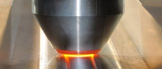
Bronze is most often used for roller electrodes. They are made in the form of pointed disks with a diameter of 35-45 cm, the width of the working rim is 4-10 mm. For welding complex workpieces, machines with two or more roller pairs are used.
The power consumption of the devices varies from 25 to 300 kilowatts.
Low-power machines are considered to be 25-40 kilowatts, average power is 4-100, high-power machines consume from 100 to 300.
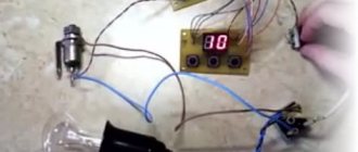
Machine MSh-2203
The medium power device MSh-2203 requires a three-phase power supply of 380 volts, an operating current of up to 22 thousand amperes. The clamping force reaches 5 tons
The resistance seam welding machine welds steel sheets up to 1 mm thick. There are two modifications - with a roller reach of 400 and 700 mm.
Test welded joint
6.1. Basic provisions
In accordance with 6.2, it is necessary to prepare a standard control welded joint, for which the entire welded product can be used.
Test specimens shall be cut from relevant parts, control welded joints or welded separately in accordance with 6.3.
It is necessary to use test specimens and control welded joints of the same material and with the same edge width and overlap length. If possible, shunting and inductive effects must be taken into account. If the applicable standard requires it, the rolling direction must be indicated on the reference welded joint.
6.2. Shape and dimensions of control welded joints and samples for destructive testing
6.2.1. Basic provisions
The shape and dimensions of test welded joints and test specimens and welding procedure testing are given in the following standards: ISO 14270, ISO 14271, ISO 14272, ISO 14273, ISO 17653 and ISO 10447.
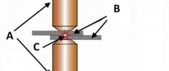
6.2.2. Macro sanding
The test specimen must be prepared and etched to produce transverse and longitudinal sections to identify inclusions, the heat-affected zone and, if necessary, the cross-section of the weld.
The transverse macrosection must contain intact base metal.
6.3. Welding control welded joints or test specimens
The preparation of units (parts), control welded joints or test specimens and welding of control welded joints or test specimens must be carried out in accordance with pWPS and in accordance with the general rules for welding work (parameters, equipment, etc.).
If tacks are used during spot welding, they must also be on the final control welded joint.
Before certification, the welding procedure and test program for control welded joints must be agreed upon with the expert or expert body.
Terms used by GOST
GOST 15878-79 regulates the following structural elements of resistance welding:
- thickness of welded parts (from 0.3 to 6.0 mm). It is possible to work on parts of different thicknesses. In this case, calculations are made for a part with a smaller thickness. When one thickness is two times greater than another, all parameters increase by 1.2 - 1.3 times. This indicator, along with the type of metals being fused and the physical and mechanical requirements for the structures being manufactured, sets all other parameters of the technological process. In GOST they are presented in the form of tables;
- calculated : melting point diameter and seam width (not less than 1.5 - 16 mm). Within these dimensions, the melt will solidify and create a monolithic joint;
- the total length of the cast, overlapped and uncovered section of the seam . This is a characteristic of seam welding (when considering its longitudinal section). To ensure the tightness of the seam, the size of the overlapped zone must be at least 25% of the total length of the cast section. In the case of creating a seam for metals with a thickness of less than 0.3 mm, the size of the overlap can be reduced (without loss of tightness);
- the amount (depth) of penetration (from 20 to 95% of the thickness of the parts, depending on their material);
- distances between points for different patterns of their location . Between centers in one row from 7 to 65 mm. Between rows from 8.5 to 78 mm;
- number of rows of dots.
Tests and evaluation of results
7.1. Scope of control
Testing includes both non-destructive and destructive tests.
The choice of the type of testing and the number of test specimens depends on the operating conditions and requirements for the quality of the welded product. The type of tests and the number of samples must be established before certification (Table 1).
If there is no need to determine the standard deviation of test results in the transverse and longitudinal directions, then a smaller number of samples may be used.
Table 1 - Examples of testing spot, seam and projection welded joints
| Control welded joints/test specimens | Type of test | Number of samples |
| Single point spot or projection welding specimen | Visual inspection | All |
| Shear tests | 11 | |
| Stretchinga) | 11 | |
| Macro sandb) | 2 | |
| Hardness | If you want to | |
| Torsion testc) | 11 | |
| Pull tests | 11 | |
| Chisel test | 11 | |
| Two-point spot or projection weld sampled) | Visual inspection | All |
| Shear tests) | 11 | |
| Stretching (cross)a) | 11 | |
| Macro sandb) | 2 | |
| Hardnessf) | If you want to | |
| Pull tests | 11 | |
| Chisel test | 11 | |
| Multi-point or relief patternsg) | Visual inspection | All |
| Shear (shear) testsh) | 11 | |
| Macro sandb) | 11 | |
| Hardnessf) | 2 | |
| Pull tests | If you want to | |
| Chisel test | 11 | |
| Samples of lap seam welding (control welded joints) | Visual inspection | All |
| Delamination tests | 11 | |
| Shear (shear) tests | 11 | |
| Pull tests | 3 | |
| Leak test | 3 | |
| Macro sanding) | 2 | |
| Hardnessf) | If you want to | |
| Seam welding with edge crushing | Visual inspection | All |
| Shear testsm) | 11 | |
| Bending testsn) | 2 | |
| Pull tests) | 9 | |
| Bloatj) | 3 | |
| Leak testk) | 3 | |
| Macro sanding) | 2 | |
| Hardnessf) | If you want to | |
| a) Instead of a shear test. b) Two specimens offset by 90° and clamped perpendicular to the plane of the plate. Limitation of deformation on the main axes must be established. c) Instead of a shear test, if it is not possible to prepare a standard specimen or in cases where torsion predominates. d) Only for single-sided current supply. f) The two-point connection must be cut into single-point specimens. The deviation of the sample width from the standard depends on the dot pitch. f) Point-to-point connection. g) A multi-point seam must be made with the points arranged in the same way as is done on the finished product. h) If the spot weld is made in the same manner as for the two-point tests. i) Instead of a tensile test in case of predominant shear load. j) Only if there are requirements for tightness (hydrotest). k) Only if there are increased requirements for tightness (leak detection). l) One longitudinal and one transverse sample. m) If possible, with a right angle to the seam. n) External and internal sides. o) For seam welding only: three samples - from the beginning, middle and end of the seam. | ||
7.2. Arrangement and cutting of test specimens
Test specimens should be selected after visual inspection or other alternative tests.
Cutting samples according to 6.2.
It is allowed to cut test samples from areas that do not contain acceptable defects.
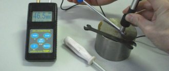
7.3. Visual control
Spot welds and seam welds should be inspected using a 6x to 10x magnification loupe, mirror, or endoscope to determine the following surface characteristics: surface cracks, metal burnout, spatter, electrode material deposition, electrode gouges and discontinuity.
7.4. Repeated tests
If a part or test weld does not satisfy any visual inspection requirement or any other type of inspection, then another additional part or test weld must be inspected. If this additional part or the test weld does not satisfy the requirements, the pWPS must be changed. Modified pWPS shall be qualified in accordance with this standard.
If any test specimen does not satisfy the essential requirements of 6.2 due to geometric defects (e.g. position, shape), then additional test specimens must be made, one for each failure. These samples can be taken from the same control weld if there is enough material in it, or from a new joint
If any of these additional samples do not satisfy the basic requirements, then the pWPS must be changed. Modified pWPS shall be qualified in accordance with this standard.
Scope of certification
8.1. Basic provisions
All requirements listed below must be applied independently of each other.
If the parameters are outside the acceptable limits, new tests of the welding procedure are necessary.
8.2. Manufacturer related
Certification of pWPS through testing in accordance with this standard allows welding work to be carried out in workshops and on sites under simultaneous technical and quality control by the manufacturer.
Technical control and quality control shall apply to a welding procedure if the manufacturer who has qualified the welding procedure takes full responsibility for welding performed in accordance with that procedure.
8.3. Related to the material
All tests must be carried out using materials similar to those used in production (thickness, chemical composition, mechanical properties). In case of deviations from these requirements, all changes must be established before certification.
8.4. Common to all welding procedures
8.4.1. Welding process
The qualification applies only to the welding process used during testing.
Where equipment has remote control or more than one welding program used in a job as part of a sequence of operations, the WPS must contain a description of all welding programs used.
For automatic or robotic control of more than one welding program, the WPS must contain a description of all welding programs used, each of which requires qualification.
8.4.2. Type of current
The welding procedure is qualified by the type of current (alternating, direct or pulsed), frequency and polarity used in testing the welding procedure.
8.4.3. Welding cycle
The welding procedure is qualified by the welding cycle used in welding.
8.4.4. Heat treatment after welding
Any heat treatment provided shall be taken into account when testing the welding procedure.
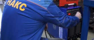
8.4.5. Type of welding equipment
Welding procedures are qualified by the type of testing equipment used.
8.4.6. Welding electrodes
Welding procedures are qualified by the materials and design of the electrodes used.
Stitching machines
In addition to stationary welding machines, manufacturers also produce portable or hanging devices. They are designed for welding thin-walled products of complex configuration. The power source is still located on the workshop floor, and the rollers and clamping device are mounted on movable pliers. Using an articulated pneumatic drive, the pliers are installed in the position required for work.
Seam pliers
Welding procedure certification protocol
The Welding Procedure Qualification Report (WPQR) is a report of the results of the evaluation of each test joint, including retests. The main points listed for WPS in ISO 15609-5 along with the description of the characteristics given in clause 7 should be included in the protocol.
If no unacceptable test results are found, the WPQR describing the test results is considered positive and must be signed and dated by the examiner or examining body.
WPQR should be designed to make the data easier to understand.
Application ZA (required)
Information on the compliance of reference international standards with reference European standards
The documents presented below are necessary for the application of this standard. For dated references, only the edition referred to applies. For undated references, the current edition of the document referred to (including any amendments) applies.
| Publication | Year | Name | EH | Year |
| ISO 14732 | 1998 | Welding personnel. Qualification testing of fusion welding operators and resistance welding setters for fully mechanized and automatic welding of metallic materials | EN 1418 | 1997 |
Machine design for seam contact welding
The main supporting structure of the device is the frame. All other components are attached to it:
- power supply;
- fixed roller bracket;
- movable roller bracket;
- clamping device;
- workpiece feed mechanism
The clamping device can be manual, pneumatic, hydraulic or combined. The manual (more precisely, foot) drive has the least power.
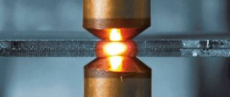
The roller electrodes are made in the form of bronze disks tapering towards the edges; they are secured to the ends of the brackets using plain bearings.
Machine design for seam contact welding
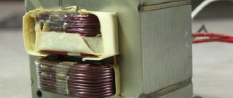
The power source provides periodic supply of high power current to the electrodes. It also powers the drive of the clamping device and the feed mechanism. The power supply of modern devices is made using an inverter pulse circuit with double voltage conversion. This allows you to reduce the size of the device and eliminate voltage surges in the supply network.
Appendix YES (reference)
Information on the compliance of reference international standards with reference national standards of the Russian Federation
Table DA.1
| Designation of the reference international standard | Degree of compliance | Designation and name of the corresponding national standard |
| ISO 669:2000 | — | * |
| ISO 10447 | — | * |
| ISO 14270 | — | * |
| ISO 14271 | — | * |
| ISO 14272 | — | * |
| ISO 14273 | — | * |
| ISO 14732 | MOD | GOST R 53526-2009 “Personnel performing welding. Qualification testing of fusion welding operators and resistance welding setters for fully mechanized and automatic welding of metal materials" |
| ISO 15607 | IDT | GOST R ISO 15607-2009 “Technical requirements and certification of welding procedures for metallic materials. General rules" |
| ISO 15609-5 | — | * |
| ISO 17653 | — | * |
| *There is no corresponding national standard. Before its approval, it is recommended to use the Russian translation of this international standard. A translation of this international standard is located in the Federal Information Fund of Technical Regulations and Standards. Note - This table uses the following conventions for the degree of compliance with standards: — IDT — identical standards; — MOD — modified standards. | ||
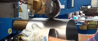
Roller stand for contact welding
To weld structures in the shape of a cylinder (or a system of mating cylinders), roller stands are used. They are distinguished by a large overhang of the roller brackets, which makes it possible to weld fairly large and extended structures. The stand is equipped with a large number of adjustable supports, allowing you to secure cylindrical workpieces of different lengths and diameters. The roller electrodes are driven by a worm gear. The workpieces rotate on the stand, and thus the rollers pass the entire seam line. The stands produce smooth and sealed seams of high strength.
Roller stand for contact welding