Cold or hot metal drawing is a type of metal forming. Using these methods, an assortment of round and shaped wires, rods, pipes and other products made of ferrous, non-ferrous metals and alloys are produced that are sold in the retail chain. For this purpose, drawing equipment is used, which, according to the kinematic principle, makes it possible to obtain products of the required diameter using single and multiple drawing methods. Twisted fittings, wire, metal ropes, mesh and fasteners are obtained from products made by drawing, where a drawing machine or machine is used. Products obtained by drawing are used in various industries, agriculture and by home craftsmen.
The essence and purpose of the drawing operation
The essence of the drawing process is to pull a metal workpiece of a larger diameter through a hole of the required shape and obtain a product of a smaller diameter. Manufactured products are characterized by the quality of the outer surface, density and accuracy of cross-sectional dimensions. Operations are performed on special machines called drawing mills. They increase labor productivity: the labor intensity of manufacturing becomes much lower than when producing such products by other methods.
Drawing mills are produced by manufacturers with rectilinear movement of the workpiece and with winding on drums. In the latter case, they can be with one or more driving drums, which allows one or several workpieces to be drawn at the same time.
Metal drawing
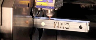
Drawing is one of the oldest methods of OMD. Its essence lies in drawing a cold rod through a hole (hole, die), the output dimensions of which are smaller than the dimensions of the original section of the workpiece (see Fig. 1.4). The method is widely used in metallurgy and metalworking. The range of resulting products includes profiles with a diameter from several microns to 100 mm, not only round, but also the most exotic shapes of solid or hollow cross-section made of noble, non-ferrous and ferrous metals and alloys.
If the only goal is to increase accuracy and improve the surface quality of the product, then this type of drawing is called calibration.
The degree of deformation during drawing is limited by the drawing force, which should not cause the appearance of stresses at the front end exceeding 0.5...0.7 of the yield strength of a given metal. Therefore, single draws during drawing are only 1.2...1.3 and rarely reach 1.5.
The drawing force largely depends on the friction coefficient. To reduce it, lubricants are used (for example, soap shavings with various fillers).
The use of roller dies instead of monolithic ones has a great effect, but due to their complexity they are rarely used, although the drawing coefficient in such dies can reach 4...5.
Usually the die consists of two parts - the holder and the die itself (Fig. 13.1). The cage is made of strong tough steel, and the die is made of carbide materials. For drawing the finest wire, dies are made from industrial diamonds, and for drawing rods and pipes of large cross-sections - from tool steels.
The drag consists of several sections (Fig. 13.1). The middle section is the working or deforming zone. Has a conical shape. On the entrance side it is adjacent to a lubrication zone, also conical in shape, and on the other side there is a calibrating belt, which gives the final shape to the profile. The lubrication zone is adjacent to the inlet zone, and the calibrating belt is adjacent to the outlet zone of a conical or spherical shape.
The angle of the working cone (2a) is taken equal to 8...24o, the lubrication zone - 20...60o, and the inlet and outlet zones - 60...90o. The length of the working cone is 0.5...0.7, and the length of the calibrating belt is 0.3...1.0 of the diameter of the resulting profile.
Hollow products are drawn in several ways (Fig. 13.2): on a short fixed mandrel, on a long movable mandrel, on a short “floating” mandrel and without a mandrel.
Drawing forces are determined either experimentally using force measuring instruments (for example, dynamometers) or analytically.
Drawing mills. The main elements are a drawing tool and a pulling device. Two main types of mills are used: with linear movement of the drawn metal (chain, rack, hydraulic) and with winding on a drum (drum mills).
The former are used for profiles that cannot be wound due to their size or shape.
The chain mill consists (Fig. 13.3.) of a frame 3, an endless chain 2, a trolley with a gripper 4, a stand for fastening the dies 5, a motor with transmission devices 1.
On modern mills, it is possible to simultaneously draw up to 10 bars at a speed of up to 2 m/sec, with a pulling force of up to 1.5 MN. The length of the products is limited by the dimensions of the frame and is usually up to 15 m (maximum up to 50 m).
Drum mills, depending on the number of dies through which the metal is sequentially pulled, are divided into single and multiple.
Single-use ones are used for drawing rods, shaped profiles and pipes. The drum axis is vertical or horizontal. The drum is both a pulling and winding device. To avoid distortion of the profile shape during winding, the diameter of the drum should be 30...40 times greater than the diameter of the product being wound (up to 3 m). Drawing force is up to 100 KN, drawing speed is up to 4.5 m/sec.
The principle of operation of multiple drawing mills (Fig. 13.4) is to simultaneously pull the workpiece through several sequentially located dies. When leaving one die, the end of the metal is wound onto a drum, and then unwinds from it and through a system of guide rollers enters the next die, etc. Mainly used for wire drawing. The multiplicity of drawing is determined by the number of dies (6...9 or more). Drawing speed up to 20 m/sec.
Basic technological operations during drawing.
The workpiece supplied for drawing may have different structure and mechanical properties along the length, which negatively affects the drawing conditions. Therefore, preparing metal for drawing begins with heat treatment.
1. Heat treatment of the workpiece is intended to homogenize the structure and increase plastic properties. Depending on the material, annealing, normalization, hardening and tempering, and patenting are used.
Patenting is most widely used in the preparation of wire rod from carbon steels. Provides a fine-grained sorbitol metal structure. It consists of heating the workpiece to the austenitization temperature and cooling it in a lead (salt) bath at a temperature of 450…500°C. The process is carried out continuously.
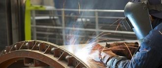
2. Removal of scale from the surface of the workpiece is carried out chemically or mechanically. Pickling is carried out in continuous pickling units in solutions of sulfuric or hydrochloric acids. With the mechanical method, scale is often removed by repeated bending in two planes, followed by treatment with metal brushes.
3. After etching, the surface of the workpiece is thoroughly washed in hot and cold water under a pressure of approximately 1 MPa.
4. Applying a lubricating layer. To better retain the lubricant, a thin layer of various materials is applied to the surface of the workpiece: iron oxide hydrate (yellowing operation), copper (copper plating), lime (liming), Fe, Mn phosphates, etc. (phosphating).
5. Drying the coils in chambers at a temperature of 300-750o.
6. Drawing. Compression per pass is 10...30%, total 75...85% for steel and up to 95% for non-ferrous metals.
If, upon reaching the maximum reduction, the specified wire size is not obtained, repeated drawing is carried out with all preparatory operations performed.
7. Finishing operations: heat treatment, straightening, grinding, polishing, applying protective coatings (galvanizing, tinning, aluminizing, enameling, varnishing, etc.) depending on the purpose of the products.
Drawing is one of the oldest methods of OMD. Its essence lies in drawing a cold rod through a hole (hole, die), the output dimensions of which are smaller than the dimensions of the original section of the workpiece (see Fig. 1.4). The method is widely used in metallurgy and metalworking. The range of resulting products includes profiles with a diameter from several microns to 100 mm, not only round, but also the most exotic shapes of solid or hollow cross-section made of noble, non-ferrous and ferrous metals and alloys.
If the only goal is to increase accuracy and improve the surface quality of the product, then this type of drawing is called calibration.
The degree of deformation during drawing is limited by the drawing force, which should not cause the appearance of stresses at the front end exceeding 0.5...0.7 of the yield strength of a given metal. Therefore, single draws during drawing are only 1.2...1.3 and rarely reach 1.5.
The drawing force largely depends on the friction coefficient. To reduce it, lubricants are used (for example, soap shavings with various fillers).
The use of roller dies instead of monolithic ones has a great effect, but due to their complexity they are rarely used, although the drawing coefficient in such dies can reach 4...5.
Usually the die consists of two parts - the holder and the die itself (Fig. 13.1). The cage is made of strong tough steel, and the die is made of carbide materials. For drawing the finest wire, dies are made from industrial diamonds, and for drawing rods and pipes of large cross-sections - from tool steels.
The drag consists of several sections (Fig. 13.1). The middle section is the working or deforming zone. Has a conical shape. On the entrance side it is adjacent to a lubrication zone, also conical in shape, and on the other side there is a calibrating belt, which gives the final shape to the profile. The lubrication zone is adjacent to the inlet zone, and the calibrating belt is adjacent to the outlet zone of a conical or spherical shape.
The angle of the working cone (2a) is taken equal to 8...24o, the lubrication zone - 20...60o, and the inlet and outlet zones - 60...90o. The length of the working cone is 0.5...0.7, and the length of the calibrating belt is 0.3...1.0 of the diameter of the resulting profile.
Hollow products are drawn in several ways (Fig. 13.2): on a short fixed mandrel, on a long movable mandrel, on a short “floating” mandrel and without a mandrel.
Drawing forces are determined either experimentally using force measuring instruments (for example, dynamometers) or analytically.
Drawing mills. The main elements are a drawing tool and a pulling device. Two main types of mills are used: with linear movement of the drawn metal (chain, rack, hydraulic) and with winding on a drum (drum mills).
The former are used for profiles that cannot be wound due to their size or shape.
The chain mill consists (Fig. 13.3.) of a frame 3, an endless chain 2, a trolley with a gripper 4, a stand for fastening the dies 5, a motor with transmission devices 1.
On modern mills, it is possible to simultaneously draw up to 10 bars at a speed of up to 2 m/sec, with a pulling force of up to 1.5 MN. The length of the products is limited by the dimensions of the frame and is usually up to 15 m (maximum up to 50 m).
Drum mills, depending on the number of dies through which the metal is sequentially pulled, are divided into single and multiple.
Single-use ones are used for drawing rods, shaped profiles and pipes. The drum axis is vertical or horizontal. The drum is both a pulling and winding device. To avoid distortion of the profile shape during winding, the diameter of the drum should be 30...40 times greater than the diameter of the product being wound (up to 3 m). Drawing force is up to 100 KN, drawing speed is up to 4.5 m/sec.
The principle of operation of multiple drawing mills (Fig. 13.4) is to simultaneously pull the workpiece through several sequentially located dies. When leaving one die, the end of the metal is wound onto a drum, and then unwinds from it and through a system of guide rollers enters the next die, etc. Mainly used for wire drawing. The multiplicity of drawing is determined by the number of dies (6...9 or more). Drawing speed up to 20 m/sec.
Basic technological operations during drawing.
The workpiece supplied for drawing may have different structure and mechanical properties along the length, which negatively affects the drawing conditions. Therefore, preparing metal for drawing begins with heat treatment.
1. Heat treatment of the workpiece is intended to homogenize the structure and increase plastic properties. Depending on the material, annealing, normalization, hardening and tempering, and patenting are used.
Patenting is most widely used in the preparation of wire rod from carbon steels. Provides a fine-grained sorbitol metal structure. It consists of heating the workpiece to the austenitization temperature and cooling it in a lead (salt) bath at a temperature of 450…500°C. The process is carried out continuously.
2. Removal of scale from the surface of the workpiece is carried out chemically or mechanically. Pickling is carried out in continuous pickling units in solutions of sulfuric or hydrochloric acids. With the mechanical method, scale is often removed by repeated bending in two planes, followed by treatment with metal brushes.
3. After etching, the surface of the workpiece is thoroughly washed in hot and cold water under a pressure of approximately 1 MPa.
4. Applying a lubricating layer. To better retain the lubricant, a thin layer of various materials is applied to the surface of the workpiece: iron oxide hydrate (yellowing operation), copper (copper plating), lime (liming), Fe, Mn phosphates, etc. (phosphating).
5. Drying the coils in chambers at a temperature of 300-750o.
6. Drawing. Compression per pass is 10...30%, total 75...85% for steel and up to 95% for non-ferrous metals.
If, upon reaching the maximum reduction, the specified wire size is not obtained, repeated drawing is carried out with all preparatory operations performed.
7. Finishing operations: heat treatment, straightening, grinding, polishing, applying protective coatings (galvanizing, tinning, aluminizing, enameling, varnishing, etc.) depending on the purpose of the products.
Types and methods of drawing
Drawing is performed on a drawing mill.
Structurally, the device consists of the following main parts: a die (die), mandrels of various designs, broaching and auxiliary devices for automation and mechanization of the process. In this case, the drawing machine of a rectilinear design is distinguished according to the principle of operation of the main motor of continuous action (track), hydraulic, chain and rope. The process is classified according to the following parameters:
- by type (wet, dry);
- heating the workpiece (cold, hot);
- number of drawn workpieces (1, 2, 4, 8);
- degree of purity of the resulting product (rough, finishing);
- mobility of the drag (stationary, movable);
- number of transitions (single and multiple);
- method of traction (hydraulic, drum, chain).
The variety of parameters has given rise to a huge number of manufactured units, differing in technical characteristics, work technology and productivity.
Drawing is used to produce pipes with a diameter of 0.3÷500 mm with a wall thickness of 0.05÷6 mm. In this case, manufacturing methods can be as follows:
- draft;
- profiling method;
- hydrodynamic friction;
- on a special mandrel (fixed short, long movable, floating);
- on a deformable core;
- with distribution of a pipe-shaped workpiece.
The method, and therefore the equipment for it, is chosen depending on the requirements for the finished product and the brand of the workpiece used. Pipes are manufactured using a chain and drum drawing mill. In the latter case, drawing is called coil drawing.
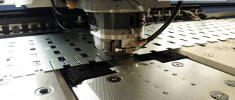
Special mills for broaching
Metal can be processed by drawing in several passes. The picture will be presented for illustrative purposes.
As for the blanks, they are most often made of non-ferrous metal and steel. The initial section can be equal to 0.01 mm. The equipment differs in the type of die that is installed on it. Let's say that mills with diamond dies are used only for the thinnest products. Carbide die is used for medium and thick workpieces. Steel equipment is used only for working with the largest products.
The design of the mills itself can also differ quite a lot. Some of them can reach processing speeds of up to 50 meters per second. Others may be equipped with more than two dozen portages at once. Certain designs allow you to work both with and without sliding. Drums for coil processing can be horizontal or vertical; there may be an individual or group type electric drive.
Main stages of the process
The final product obtained by drawing is subject to certain requirements, which are indicated in the technological characteristics. The workpiece goes through certain stages that affect the final result. They are as follows:
- annealing of the workpiece to obtain a fine-grained structure and increase plastic properties;
- removing scale from the workpiece surface;
- washing the workpiece after etching in a sulfuric acid solution;
- applying a special layer, the composition of which depends on the material of the workpiece;
- drawing on the mill;
- elimination of hardening;
- finalization of the resulting products (trimming to the required length, finishing the ends).
As a rule, they affect the density, hardness, fluidity, electrical resistance of the material (increase), plastic, anti-corrosion properties (decreases). This manifestation, called cold hardening, is eliminated by heat treatment - normalization, patenting, tempering, annealing. The choice of method depends on the grade of metal or alloy and the conditions of the drawing process.
Descaling Information
It is necessary to carefully prepare the surface for further processing. Then the result of the drawing process will be much better. To remove scale, modern production uses the following technologies:
- Electrochemical method.
- Mechanical method.
- Chemical option. For example, when an emulsion is used to draw copper wire.
The machining technique is the most common when creating carbon steel workpieces. From an economic point of view, this solution is most in demand. And the procedure itself is performed without additional complications.
First, the wire is laid between the rollers of a special structure, then it is periodically bent in different planes. Finally, metal from wire rod and other variants is cleaned using special brushes.
The chemical method of getting rid of scale will require a serious investment of money. In this case, hydrochloric or sulfuric acid is used. And for the employees themselves, the operation is associated with increased danger. Therefore, such processes are used only when other options are not available for one reason or another.
Only those who have undergone special training are allowed to access the equipment and the work itself. Chemical options for the procedure will become indispensable if scale needs to be removed from stainless, acid-resistant, high-alloy steel grades. This is a great option for those who are concerned about how to protect the cable from abrasion while drawing.
Electrochemical cleaning involves electrolytic etching. The technology is divided into cathode and anode varieties. The effectiveness and safety of the second option is higher. In this case, the role of the anode is played by the workpiece being cleaned. The cathode becomes copper, iron or lead.
Cathodic etching poses a great danger due to the fact that it actively releases hydrogen into the atmosphere. Scale separation is practically uncontrolled. Because of this, so-called “etching fragility” is formed. The design does not change its original properties.
The workpiece must be thoroughly washed after scale has been removed from it using a chemical method. Otherwise, the design will not get rid of problematic elements:
- iron salts;
- mud;
- sludge;
- remnants of etching elements;
- acid solution.
These components will simply dry out if not treated immediately after the operation is completed. First, the structure is washed in cold water, then the pressure is applied to cold water. The pressure value with annealing is approximately 700 Pa.
Video: wire drawing in Germany.
Equipment and machines for drawing
A drawing machine with a direct or alternating current drive can be used for single or multiple drawing.
In the latter case, the metal workpiece passes through several dies, changing its profile or diameter downward sequentially. The single-shot drawing machine is used for workpieces with a diameter of 8 to 20 mm. From a special unwinding device, the workpiece, after passing through the die, is wound onto a drum whose diameter does not exceed 750 mm. All operations on such a device are automated: the drum is served by a lift, and the stacking of workpieces is done by a hoist. Such drawing machines are used for the production of wire shaped profiles from ordinary and difficult-to-deform grades of workpieces during the operation of wire sizing. Drum and chain mills differ in the way they are wound. For drum devices, the winding of manufactured products is carried out on a special turntable; for chain devices, it cannot be wound.
In the video you can clearly see the wire making process:
We ask those who have worked on chain and drum mills to share their experience in the comments to the text, and also talk about the nuances of the technological process.
About other important features of the procedure
According to experts, the technology has only one significant drawback. This is that the wire deformation rate is too small. This happens due to the limitation caused by the strength of the exit end of the workpiece. Whatever deformation force is applied, this is the result we get. Drawing marks are also different.
The starting material must always be rolled, pressed, or continuously cast. This applies to carbon and alloy steels, non-ferrous metals. Casting will be of high quality only if there is a certain structure at the base. Then you can forget about traces of stains.
Patenting is a technology that has always been used for steel wires in the past. In this procedure, the material was first heated to the austenitizing temperature. And then the exposure was carried out using molten salt or lead. The exposure involved maintaining the temperature at approximately 500 degrees Celsius. This is also different from drawing.
Nowadays, you can do without such complex procedures. When leaving the rental equipment, it has become much easier to ensure the required characteristics. Each machine is equipped with a specialized cooling system. Nowadays, work processes cannot be completed without soap shavings for dry drawing.
Special types of broaching
Since today technology has developed quite significantly, sometimes drawing can be performed using one of two innovative technologies. The first is called electroplastic. The method is based on the principle that if an electric current is passed through the workpiece during drawing, the effort required for drawing is significantly reduced. This innovative method is used most often when processing alloys, which themselves are quite difficult to deform.
The ultrasonic method is used in particular for those structures that, due to their initial characteristics, are prone to such disadvantages as deformation aging, as well as a decrease in plastic properties when heated.