material provided by SIDOROV Alexander Vladimirovich
During the manufacturing process of machines, some of their parts are connected to each other, and permanent or detachable connections are formed. []
One-piece
are connections that cannot be disassembled without breaking or damaging parts. These include riveted, welded, adhesive, soldered, and conditionally interference fit joints.
Detachable
are connections that can be disassembled and reassembled without damaging parts. Detachable connections include threaded, keyed, splined and other connections.
Welded joints
are formed by local heating of parts in the welding zone. Electrical types are the most widespread, the main ones being arc and resistance welding.
The following types of arc welding
:
- automatic submerged arc welding (this type of welding is highly productive and economical, produces good seam quality, and is used in large-scale and mass production for structures with long seams);
- semi-automatic submerged arc welding (used for structures with short intermittent seams);
- manual welding (used in cases where other types of arc welding are irrational, this type of welding is low-productive, the quality of the weld depends on the qualifications of the welder).
contact welding
used in serial and mass production for lap joints of thin sheet metal (spot, seam contact welding) or for butt joints of round and strip metal (butt contact welding).
Advantages of welded joints
:
- low cost of connection due to low labor intensity of welding and simplicity of weld design;
- relatively small weight of the structure (15-25% less than the weight of the riveted one):
- due to the absence of holes for rivets, a smaller area of welded parts is required;
- the parts can be connected without overlays;
- there are no protruding massive rivet heads;
Disadvantages of welded joints
:
- the strength of the weld depends on the qualifications of the welder (it can be eliminated by using automatic welding);
- warping of parts due to uneven heating during the welding process;
- insufficient reliability under significant vibration and shock loads.
Interference connections
are carried out by selecting the appropriate fits, in which the interference is created by the necessary difference in the landing dimensions of the parts placed on one another. The mutual immobility of the connected parts is ensured by friction forces arising on the contact surface of the parts.
Connections of parts with interference are conventionally classified as permanent connections, although, especially with hardened surfaces, they allow disassembly and reassembly of parts. For this use:
- mechanical interface;
- thermal landings;
- cooling of the covered part.
Advantages of interference connections
:
- simplicity of design and good alignment of the parts to be connected;
- high load capacity.
Disadvantages of interference connections
:
- complexity of assembly and, especially, disassembly;
- dissipation of joint strength due to fluctuations in actual fitting dimensions within tolerances.
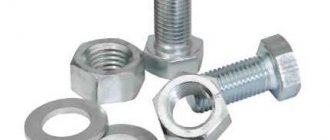
Threaded connections
are the most common detachable connections. They are formed by bolts, screws, studs, nuts and other threaded parts.
Threads are classified
depending on the:
- shape of the surface on which the thread is formed: cylindrical;
- conical;
- triangular;
- right (the helix rises from left to top to right);
- single-pass;
- fastening (used in threaded connections; they have a triangular profile, which is characterized by high friction, which protects the thread from self-unscrewing, as well as high strength and manufacturability);
Advantages of threaded connections
:
- high load capacity and reliability;
- availability of a large range of threaded parts for various operating conditions;
- ease of assembly and disassembly;
- low cost due to standardization and high-performance manufacturing processes.
Disadvantages of threaded connections
:
- the presence of a large number of stress concentrators, which reduce fatigue resistance at variable stresses.
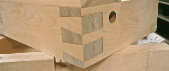
Keyed connections
consist of a shaft, key and hub of the female part.
Key
is a beam inserted into the grooves of the shaft and hub to transmit torque between the shaft and the female part.
Keyed connections are divided into
on the:
- unstressed (when assembling connections, no pre-stresses arise in the parts): with feather keys (the working edges are lateral, they do not hold the parts from axial displacement along the shaft) based on the shape of the ends they are distinguished: with rounded ends (Figure 1, version 1);
- with flat ends (Figure 1, version 2);
- with one flat and the other rounded end (Figure 1, version 3);
- with wedge keys (they have the form of single-bevel self-braking wedges with a slope of 1:100, do not require locking the hub from longitudinal movement along the shaft, and are good at absorbing shock and alternating loads) (Figure 3);
Figure 1 — Connections with parallel keys
Figure 2 - Connection with a segment key: 1 - setscrew; 2 — spring lock ring
Figure 3 — Connection with a taper key
Figure 4 — Connection with tangential keys
Advantages of keyed connections
:
- simplicity of design;
- comparative ease of installation and dismantling.
Disadvantages of keyed connections
:
- the keyway weakens the shaft and hub of the female part not only by reducing the cross-section, but, most importantly, by a significant concentration of bending and torsion stresses;
- labor-intensive manufacturing.
Spline connections
are formed by protrusions - teeth on the shaft and corresponding depressions -
splines
in the hub of the female part. The working sides are the sides of the teeth. Simply put, spline connections can be considered as multi-key connections.
Spline connections are distinguished
:
- by the nature of the connection: fixed (for securing the female part to the shaft);
- movable (allow the part to move along the shaft);
- by outer diameter (most technologically advanced);
- straight-sided (have a constant thickness of teeth) (Figure 5);
Figure 5 - Straight spline connection
Figure 6 — Involute spline connection
Figure 7 - Triangular spline connection
Advantages of spline connections
(compared to keyed connections):
- provide better alignment of the parts to be connected and more accurate direction during axial movement;
- the number of connection parts is reduced (a spline connection is formed by two parts, a keyed connection is formed by three or four);
- with the same dimensions, they allow the transmission of large torques due to the larger contact surface;
- ensures high reliability under dynamic and reverse loads;
- the shaft is weakened slightly by the teeth;
- The length of the hub decreases.
Disadvantages of spline connections
(compared to keyed connections):
- more complex manufacturing technology;
- higher cost.
Classification
The different types of compounds can be divided into two main groups. The first of which, according to the principle of operation:
- Movable. Parts can move relative to each other.
- Fixed. Both parts of the part are rigidly fixed to each other.
In turn, each type of previous classification can be carried out in two connection methods:
- Detachable. It is used when periodic replacement of parts, assembly and disassembly of the mechanism as a whole is required. These are the following types of connections: threaded (using running bolts), toothed, keyed, etc.
- One-piece. Such connections can only be dismantled using mechanical action, which destroys the mating parts. What types of connections are these? Among them are welding, gluing, riveting, flaring, crimping, interference fit, stitching, core punching, etc.
So, let's take a closer look at the main types of parts connections.
Installation of networks using sleeves
This option claims to be the most reliable connection method. Any load and quality of wires.
Crimping wires with sleeves
The conductive wires are inserted into a special tube - a sleeve, and crimped with a certain force. There is one thing, but. The cross-section of the wires should not exceed the cross-section of the mounted sleeves. Having inserted and crimped the clip, the sleeve is carefully insulated with heat-shrinkable tubing or other insulating materials.
Overall rating. A great way to securely connect wires. The direction of the conductors can be on different sides of the tube or on one side. The sleeves are quite inexpensive. A good way to reliably connect wires to each other.
There are also disadvantages. Disposable use of sleeves, they are not dismountable. To carry out such work you will need a tool: pressing pliers, which are also used as a special tool. They remove the insulation. They have a crimping device in their arsenal, and electrical installation work takes a little longer.
Threaded method
An old and long-tested mounting option. The following elements are used for it: bolts, screws, studs, screw ties and others. Fastening is carried out through threads on the fastener and in the hole of the part.
Spiral projections on the rod and in the technological hole of the parts are called threads. Let's look at the main fasteners:
- A bolt is a threaded rod with a fastening head at one end. Its shape can be hexagonal, square, round, etc.
- The screw differs from the previous product in that there is a slot (slot) for a screwdriver on the head. It can be hexagonal, straight, cross, etc. According to the type of head, products can be countersunk, cylindrical, semicircular, semi-countersunk.
- A stud is a rod with threads on both ends. Unlike previous options, it does not have a head.
- The mounting pin is slotted at one end.
- Nut is a prism with a through hole or plugged on one side.
Washers are available for these hardware: flat, spring, and deformable. This type of fixation is used everywhere.
Isolation with PPE caps
Deciphering the product is not difficult, connecting insulating clips (PPE). They are ordinary nylon or plastic caps with an internal lock.
Connection with PPE caps
The simplest type of connection of wires, it is carried out after twisting the conductors themselves, the cores. Caps are often used to connect wires in junction boxes and to mark connections with the desired color.
Assessment of the use of such products: Quite low cost of PPE. The use of safe material prevents ignition of electrical wiring. Easy installation, put it on a twist of wires and you're done. These caps have a wide range of colors, which is convenient. Of course, if the wires are not color coded, colored PPE has the ability to determine or simply mark zero, phase and other necessary electrical routes.
There are also disadvantages: Insufficient level of fixation. Multicore wires can be installed only after soldering.
Keyed
The keys secure the shaft with parts that transmit rotation and vibration. The design of such elements can be prismatic, wedge, segmental, tangential. Such fasteners form the following types of connections:
- Unstressed ones are carried out using prismatic segment keys. There is no pre-stress during assembly.
- Stressed ones are produced by tangential and segmental keys. Mounting stress appears during assembly. Used for complex mechanisms.
Soldering
Soldering is when electrical wires are joined using molten solder. This type of connection is most suitable for copper wires. Although there are now various fluxes for aluminum, experienced electricians prefer to refrain from such soldering. But if necessary, you can use special fluxes and even solder copper and aluminum.
Positive sides
This type of connection cannot be compared with twisting; soldering is much more reliable (in terms of reliability it is second only to welding).
Using soldering, you can connect stranded and single-core wires, as well as wires of different sections.
This type of connection does not require any maintenance throughout the entire period of operation.
Soldering is considered low in cost, the only equipment you need is a soldering iron, and flux and solder are very inexpensive, and their consumption is quite negligible.
Negative sides
The disadvantages of this method include high labor intensity. Soldering requires certain preparatory work; wire strands must first be tinned before twisting. The surfaces to be soldered must be free of oxides and absolutely clean before starting work.
And of course, you need experience in using a soldering iron, that is, the person who will connect the wires using the soldering method must have a certain qualification. After all, during the soldering process it is very important to maintain the required temperature conditions. An underheated soldering iron will not heat the connection well; overheating is also unacceptable, because the flux will burn out very quickly, not having time to do its job.
Soldering is a slow process, but this disadvantage is compensated by the reliability of the contact connection.
Installation
The step-by-step soldering process is as follows:
- Remove the insulation from the cores by 40-50 mm.
- Sand the bare areas of the wires until they shine using sandpaper.
- Dip a heated soldering iron into rosin and move it over the cleaned surfaces several times.
- Perform a twist.
- Bring the soldering iron tip to the solder.
- Now immediately heat the twist with solder, the tin should melt and fill the gaps between the turns.
- Thus, the entire twist is enveloped in tin, after which it is allowed to cool.
- Wipe the hardened solder with alcohol and insulate it.
Soldering wires with a soldering iron is shown in this video:
Soldering wires using a gas soldering iron:
Soldering twists by immersion in molten solder:
Toothed (spline) connections
The fastening occurs due to the protruding teeth on the shaft and the recess under them in the hub.
Dimensions are fixed by standards. This method is used for movable and fixed fastenings.
There are three options for fixation in terms of rigidity: light, medium, high. The difference is in the number and height of the teeth. It lies in the range of 6-20 pieces. Tooth Shape:
- Triangular ones are in little demand. Used for small stationary shafts and low torque.
- Straight-sided. Centered along the side edges, along the inner and outer diameters.
- Involute. Suitable for large shafts.
Where are these types used? The purpose of connections of this type is to transmit torque. The most well-known application is in power tools.
We looked at detachable mounts. Next, we will study the main types of permanent connections.
Detachable connections, their classification and purpose
Classification and purpose of detachable connections
Detachable connections include: threaded connections, connections using pins, wedges and keys, as well as toothed (spline) connections and others.
The detachable connection allows for repeated disassembly and subsequent reassembly; in this case, the integrity of the parts included in the connection is not compromised.
Threaded connections
Threaded connections are connections in which one of the parts has an external thread and the other has an internal thread. This connection is obtained by screwing one part onto another.
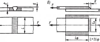
Bolted connection
It consists of a bolt, nut and washer and fastened parts. In parts 1 and 2, a hole is drilled with a diameter larger than the diameter of the bolt thread ( ). Insert bolt 3 into the hole, put on washer 5 and screw on nut 4 (Figure 17.1).
Features when performing a bolted connection:
- In the connection drawing, only three dimensions are indicated: thread diameter, bolt length and hole diameter in the parts being fastened;
- The bolt head and nut in the main image are usually shown with three faces;
Hairpin connection
A stud connection consists of a stud, nut, washer and fastened parts (Figure 17.2).
A socket is drilled into part 1 and a thread is cut into it. The threaded end of the pin 3 is screwed into the socket. A hole with a diameter of 1.1 d is drilled in part 2 and put on a pin. Then put washer 5 on the stud and screw on nut 4.
Features of making a hairpin connection:
- The dividing line of the fastened parts must coincide with the thread run-out of the screwed-in threaded end of the stud;
- The pin socket ends in a cone at an angle of 120°. This cone is of a technological nature and is obtained from a drill;
Screw connection
A screw connection consists of a screw and fastened parts (Figure 17.3).
In part 1, a socket is drilled into which a thread is cut. A hole with a diameter of 1.1 d is drilled in the attached part 2. The screw fits freely into the hole in part 2 and is screwed into part 1.
The conical head of the screw, called countersunk, should not protrude above the surface of the part.
The slot in the head for the screwdriver is positioned in the front and left views perpendicular to the front and profile planes of projection, and in the top view - conventionally at an angle of 45 degrees.
If the diameter of the screw head in the drawing is less than 12 mm, then the slot is shown as one thick line.
Constructive, simplified and conventional images of threaded connections
There are constructive, simplified and conventional images of fasteners and their connections.
When constructing a design, the dimensions of the parts are selected and drawn according to the relevant standards.
In a simplified representation, the dimensions of fasteners are determined by conditional relationships depending on the thread diameter.
A conventional image is used when the diameter of the rod is less than 2 mm.
In simplified illustrations, threads are shown along the entire length of the threaded fastener shank. Chamfers, roundings, and gaps between the part rod and the hole are not shown. In views obtained by projection onto a plane perpendicular to the thread axis, the thread on the rod is depicted by one circle corresponding to the internal diameter of the thread (the arc corresponding to the internal diameter of the thread is not depicted). These same views do not show the washers used in the connection. In simplified images, the end of the part hole is not shown (Figure 17.4).
Wedge connection
A wedge connection is used when it is necessary to quickly disassemble and assemble machine parts to be connected, as well as tightening parts with adjusting the corresponding gaps between them (Figure 17.5).
A wedge is a block that has a bevel on one side with a certain slope. The wedge is rounded along the edges and ends.
Connection using pins
According to their shape, pins are divided into cylindrical and conical. Pins are used for mutual installation of parts, as well as connecting and safety parts.
Keyed connection
Keys are used for detachable connection of parts when transmitting torque and axial force. A keyed connection consists of a wheel, a shaft and a key. A key is inserted into a special groove made on the shaft and the wheel is placed on the shaft so that the groove of the wheel hub hits the protruding part of the key.
The dimensions of the key design are standardized and depend on the diameter of the shaft. There should be a small gap between the upper non-working edge of the key and the edge of the hub groove. According to their design, keys are divided into prismatic (Figure 17.7, version 1), segmental (Figure 17.8) and wedge (Figure 17.9).
Designation examples:
- parallel key - Key GOST 23360-78, where 2 is the design (one end is rounded, the other is straight); 12×8 - section; 45 - key length;
- taper key - Key GOST 24068-80 (version 1 is not specified);
- segment key - Key GOST 24071-80, where 10 is the width; 16 - height of the key (version 1 is not specified).
Spline connections
A toothed, or splined, connection of a part with a shaft is formed by protrusions on the shaft and depressions of the same profile in the bushing or hub. (A spline connection can be considered a “multi-key” connection, in which the keys are integral with the shaft and located parallel to its axis). Compared to a keyed connection, it is capable of transmitting greater torques, and it is easy to carry out overall centering of the sleeve and shaft and their axial movement.
It is used in critical mechanical engineering structures.
There are standard splines with straight-sided and involute profiles in cross section. Triangular profile splines are not standardized. The slots in the longitudinal section are not conventionally hatched. A cross-section (section) is allowed to show the profile of one tooth and two cavities. The rest are indicated by circles: the tops of the teeth are a solid main line, and the valleys are a solid thin line. The image of a spline connection (Figure 17.11) with straight-sided splines differs from the image of a connection with involute splines (Figure 17.12) in that the latter has a dividing surface line (dash-dotted line).
The main convention in depicting spline joints is that the longitudinal section shows only that part of the bushing splines that is not covered by the shaft splines.
The symbol for straight-sided splines includes: the designation of the centering surface (letters D, d or b), the number of splines z, the diameter of the recesses d, the diameter of the projections D, the width of the spline b. In addition, the designations of the tolerance fields must be indicated.
Figure 17.13 shows an example of a designation in a connection, Figure 17.14 - on a shaft, Figure 17.15 - in a hole.
Centering surface D, z=8; d = 36mm, D = 40mm, b = 7mm.
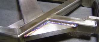
Welding
What makes them special? These types of joints are formed by heating and fusing the material at the attachment point to form a weld. This clutch is considered one of the most common.
There are several welding options. The most popular of them:
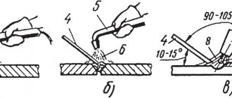
- Electric arc welding. Three main subtypes can be distinguished: automatic submerged welding (characterized by high productivity and quality, used in mass production), semi-automatic submerged arc welding (used for short intermittent welds), manual (lower productivity speed, quality depends directly on the experience of the welder).
- Contact welding. Used in mass production for thin sheet metal. The seam is made as an overlap.
One of the popular mounting options is shown in the photo.
Often used in suburban construction.
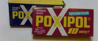
Adhesive joints
This type of fastening does not require heating of the surfaces.
Each type of metal has its own adhesive that will ensure a tight adhesion. For such operations, parts are prepared. The surface is sanded, degreased, a special primer is applied, and then a gluing operation is performed. The compositions used differ in additional properties and adhesion to various surfaces.
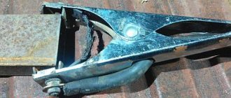
Rivet fixation
This coupling method is mainly used for joining sheet metal and shaped profiles. The technological hole in the surfaces is made by drilling, then a rivet is inserted.
Due to mechanical action, the rod and head are deformed, fill and fix the hole. This operation is performed manually and mechanized. Rivets are used to fix material that is not amenable to welding, soldering, gluing, and to parts where it is necessary to delay the destructive process.
Advantages and disadvantages of types of connections
Each fastener has its own characteristics. Let's consider all the options in terms of advantages and disadvantages:
- Threaded. Withstands heavy loads, reliable adhesion, a wide range of products, ease of installation and dismantling, the ability to use mechanization, low cost. Disadvantages: increased amount of tension concentrates, reduces resistance.
- Keyed. Simple design, easy installation and dismantling. Disadvantages: the veneer groove weakens them by reducing the cross-section of the shaft and hub. This also occurs due to concentrations of torsional and bending stresses. A labor-intensive process for manufacturing fasteners.
- Serrated. Forms good adhesion and precise direction of axial movement, transmits greater torque, fewer parts, reliability under reverse and dynamic loads, less shaft weakening, reduced hub length. Disadvantages: increased price, complex production technology.
- Welding. Low cost of work, the connection is hermetically sealed and tight, the use of automated processes, the ability to work with thick profiles. Disadvantages: in manual welding, the quality depends directly on the qualifications of the worker, deformation of the surface of parts when heated, low reliability under vibrations and shock impacts.
- Soldering. No deformation of the surfaces of parts, high accuracy, desoldering possible. Disadvantages: the process of preparing the base is complex; a minimum gap must be ensured.
- Glue. Low cost, no weakening of the working section, possibility of combined use with other types of fasteners, tightness of the joint, increases the anti-corrosion properties of the seam, resistance to water, chemicals, temperature changes, simple application technology. Disadvantages: careful preparation of the base; if the composition is incorrectly selected, the strength characteristics may be reduced.
- Riveted. Possibility of application to materials that cannot be welded, reliability, prevents the appearance of fatigue cracks. Disadvantages: labor-intensive, material-intensive, the process causes deformation of the surfaces of parts due to mechanical stress.
- Pressure connections. The design is quite simple, the parts are well arranged relative to each other, and can withstand heavy loads. Disadvantages: difficult to assemble, strength dissipates under the influence of vibrations and vibrations.
As you can see, each type has its own advantages and disadvantages. Taking these factors into account, the optimal types of fasteners are selected in each specific case. Let's look at where different connections are used.
Crimping
For this method, special tubular sleeves or lugs are used, with which the wires to be connected are crimped and crimped. The essence of the method is the joint deformation of the sleeve and the cores inserted into it. When deformed, the sleeve contracts and puts pressure on the conductive surfaces. The conductors engage in mutual adhesion, which ensures reliable electrical contact.
The advantage of such a connection is its reliability, and also the fact that it can be classified as “set and forget”; it does not require maintenance.
But along with the positive aspects, crimping also has a number of disadvantages. First, a special tool is required (a crimping press or mechanical or hydraulic pliers). Secondly, the quality of the connection directly depends on the correctly selected sleeve (it is selected depending on the number of cores being connected and their cross-section).
Before connecting two wires using crimping, they are not only stripped of insulation, but also lubricated with a special paste. Aluminum is treated with quartz-vaseline paste; it removes the oxide film and prevents it from appearing again. For copper conductors, quartz impurities are not needed; technical petroleum jelly is sufficient. It is needed to reduce friction. Lubrication also minimizes the risk of damage to the cores during deformation.
Next, the cores must be inserted into the sleeve until they mutually stop, and alternate crimping is performed on both sides. The pressed joint is insulated using insulating tape, varnished cloth or a thermal tube.
How to connect wires with sleeves is shown in these videos:
Types of connections. Application examples
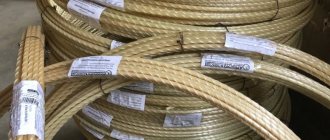
Threaded, adhesive, and welded connections are found everywhere in any industry. For example, construction, furniture, heavy industry and so on. Keyed and splined fastenings are widely used in power tools, equipment, and mechanical engineering. Interference connections are installed on the shafts of gear rings and worm wheels. Soldering is often used in electronic systems where maximum precision is required. Riveting is used for stitching together sheets of thin metal. However, as shown in the last photo, fairly large channels can be fastened using rivets. This is just a small list of the applications of individual fastening options.
We can say that with technical progress, clutch technology is rapidly developing, which means that new types of parts connections will appear. The modern world is filled with units, machines and mechanisms. The quality and service life of the components depend on how firmly the parts are secured. It is also important that the connection does not distort the shape of the product and does not introduce additional changes to the design. Therefore, it must comply with technological standards. If you follow them, the number of emergency situations at enterprises will be reduced significantly, and the units themselves will last a very long time.
So, we found out what types of connections there are.
Application in terminal block circuits
Terminal blocks are electrical products made of non-conducting material, inside of which a conductive sleeve is inserted, which has a pair of screws at opposite ends. They serve to secure the wire. An excellent choice for implementing a modern way of connecting wires.
Types of terminals for connecting wires
When choosing a reliable connection of wires, it is important to remember: terminal blocks are produced with different holes for many cross-sections.
This method is almost always used for connections in junction boxes of any type, during installation, installation of wall and other lamps. It is suitable for mounting most devices, switches and sockets. It is easy to mount a network using such fittings; you just need to insert the bare ends into the holes and, using moderate force, securely tighten the screws. The wire itself should not be crushed. Having figured out how to properly connect electrical wires using terminals, it is worth exploring other equally reliable methods.
Connecting the wire with a screw clamp
Evaluation of the terminal method: Excellent quality of fastening. Their prices are reasonable. Quite quick and easy installation. A good opportunity to connect different conductors, for example, aluminum and copper.
Sometimes the terminal blocks themselves are sold in poor quality, which threatens to break them during installation. Possibility of connecting no more than two cables of the same section into one socket. Be sure to read how to correctly connect wires by color.
It is not recommended to connect aluminum and stranded circuits with blocks. This is due to the high fragility of aluminum wires and the great flexibility of the stranded wire conductors themselves. But overall a decent method.