Technical data
- Ball screw drives, pdf, English, volume -4.41 MB:
- Instructions for the ball screw, pdf file, volume 209 kb:
SNR produces rolled and ground ball screws (Ball Screws). A wide range of nuts, processing options and extensive technical knowledge allow us to design ball screws according to the special requests of our customers.
Ball-and-wound drives are used in a wide variety of industries, such as metalworking, woodworking, aircraft manufacturing, automatic assembly lines, and semiconductor manufacturing.
Stroke variation and tolerance
The accuracy classes of ball screws are determined in accordance with ISO 3408. The accuracy determines the maximum permissible deviation of the ball screw stroke per useful stroke lu. For accuracy classes t7-t10, the average deviation on a stroke is 300 mm in any part of the thread.
lu - useful stroke - this is the stroke plus the length of the ball nut le - run-out - this is the axial stroke beyond the useful stroke, which serves for safety. Limited stroke and rigidity tolerances for useful stroke are not used. lo - nominal stroke is the axial stroke of the nominal pitch multiplied by the number of rotations of the ball nut relative to the spindle C - user-defined useful stroke adjustment. The difference between the useful and actual stroke is determined by the user (standard c=0) ep - the upper and lower limits of the actual stroke form the accuracy ranges for the average stroke Vup - the permissible deviation of the useful stroke is higher than the useful stroke lu V300p - the permissible deviation for a stroke length of 300 mm V2πp - the permissible deflection per revolution
Permissible stroke deviations
| Screw length lu, mm | Accuracy class | ||||||||||
| T0 | T1 | T3 | T5 | T7 | T10 | ||||||
| from | before | ep | vu | ep | vu | ep | vu | ep | vu | ep | vu |
| 0 | 315 | 4 | 3.5 | 6 | 6 | 12 | 12 | 23 | 23 | 52 µm / 300 mm | 210 µm / 300 mm |
| 315 | 400 | 5 | 3.5 | 7 | 6 | 13 | 12 | 25 | 25 | ||
| 400 | 500 | 6 | 4 | 8 | 7 | 15 | 13 | 27 | 26 | ||
| 500 | 630 | 6 | 4 | 9 | 7 | 16 | 14 | 32 | 29 | ||
| 630 | 800 | 7 | 5 | 10 | 8 | 18 | 16 | 36 | 31 | ||
| 800 | 1000 | 8 | 6 | 11 | 9 | 21 | 17 | 40 | 34 | ||
| 1000 | 1250 | 9 | 6 | 13 | 10 | 24 | 19 | 47 | 39 | ||
| 1250 | 1600 | 11 | 7 | 15 | 11 | 29 | 22 | 55 | 44 | ||
| 1600 | 2000 | — | — | 18 | 13 | 35 | 25 | 65 | 51 | ||
| 2000 | 2500 | — | — | 22 | 15 | 41 | 29 | 78 | 59 | ||
| 2500 | 3150 | — | — | 26 | 17 | 50 | 34 | 96 | 69 | ||
| 3150 | 4000 | — | — | 32 | 21 | 62 | 41 | 115 | 82 | ||
| 4000 | 5000 | — | — | — | — | 76 | 49 | 140 | 99 | ||
| 5000 | 6300 | — | — | — | — | — | — | 170 | 119 | ||
Tolerance for stroke changes within an interval of 300 mm (international standards)
| Accuracy class | T0 | T1 | T3 | T5 | T7 | T10 |
| e300 DIN, ISO | 3.5 | 6 | 12 | 23 | 52 | 210 |
| e300 JIS B 1192 | 3.5 | 5 | 8 | 18 | 50 | 210 |
| e2π | 3 | 4 | 6 | 8 | — | — |
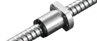
A ball screw is a more popular type of rolling screw-nut transmission. Functionally, a ball screw is a linear mechanical drive that reorganizes reciprocating motion into rotational motion (and vice versa). Structurally, it represents a screw with a nut moving along it with helical grooves of a curved profile. Inside the nut, between its thread and the screw thread, balls roll along a spiral-shaped closed path, falling into the return channel (bypass channel) - external or internal.
A simple screw drive consists of a nut and a screw. They have a trapezoidal thread. Consequently, when moving in this gear, sliding friction appears, and a lot of energy (~70%) in the form of heat.
In turn, the ball screw includes rolling elements - balls that transmit mechanical energy between the nut and the screw. What guarantees visible advantages:
1. Efficiency can be more than 80%
2. Obtaining high-precision translational motion
3. High load-bearing capacity with small dimensions
4. Service life is longer and can be determined by rolling fatigue calculation if necessary
5. Wear rate is reduced
6. Ensures continuous operation due to less heat
7. Significant resource.
There are also small disadvantages:
1. Ball screws are prone to rolling due to their low friction coefficient. As a result, a braking device is used to eliminate
independent movement of the mechanism
2. Complexity of the nut design
3. High precision of nut creation is required
4. Need protection from transmission contamination.
Ball screws with preload are assembled to eliminate axial play in the screw-nut combination and increase the accuracy and rigidity of movement. Preload removes repeating screw pitch errors and aligns the position of the nut axis relative to the screw axis. Depending on the device, preload is performed by selecting a larger diameter of the balls or selecting two nuts, with further relative axial displacement, in one housing.
The nut design and thread profile are determined by the manufacturer.
Main characteristics of ball screws.
Regarding Industry Standard 2 R31-5-89 (Metal-cutting machines. Ball screws. Technical conditions), the material for assembling and processing ball screws must comply with GOST 7599-82.
Radial clearance.
Before preload is applied, for semicircular ball screws, the radial clearance is equal to the values presented in Table 1.
The radial clearance is measured when the assembled nut is shifted in the radial direction, under the influence of a force that is 1.5 - 2 times higher than the gravity force of the given nut. It is necessary that the measuring tip of this indicator touches the outer plane of the nut.
Table 1. Ball screw radial clearance before preload
| Nominal diameter d0, mm | Thread pitch Р, mm | Radial clearance, mm | |
| maximum | minimum | ||
| 16 | 2,5 | 0,020/- | 0,056/- |
| 25 | 5,0 | 0,093/0,107 | 0,067/0,073 |
| 25 | 10,0 | 0,170/0,170 | 0,110/0,113 |
| 32 | 5,0 | 0,096/0,110 | 0,064/0,075 |
| 32 | 10,0 | 0,170/0,171 | 0,110/0,112 |
| 40 | 5,0 | 0,096/0,110 | 0,064/0,072 |
| 40 | 6,0 | 0,101/0,113 | 0,059/0,065 |
| 40 | 10,0 | 0,161/0,173 | 0,119/0,126 |
| 50 | 5,0 | 0,101/0,110 | 0,059/0,061 |
| 50 | 10,0 | 0,163/0,175 | 0,117/0,125 |
| 50 | 12,0 | 0,183/0,197 | 0,137/0,146 |
| 63 | 10,0 | 0,165/0,177 | 0,115/0,123 |
| 80 | 10,0 | 0,167/0,179 | 0,113/0,121 |
| 80 | 20,0 | 0,247/0,273 | 0,193/0,211 |
| 100 | 10,0 | 0,170/0,192 | 0,110/0,118 |
| 100 | 20,0 | 0,250/0,276 | 0,180/0,198 |
| 125 | 20,0 | 0,422/0,430 | 0,338/0,350 |
* The value after the curved line refers to screws with relief grooves.
Axial rigidity.
Axial stiffness is the ratio of the axial force affecting the transmission, which is applied to the nut group, to the axial movement of the screw if it does not turn.
The axial stiffness indicators must be greater than the indicators given in tables 2 and 3.
Table 2. Axial rigidity of housing ball screws
| Nominal diameter d0, mm | Thread pitch P, mm | Stiffness for accuracy classes, N/µm | |||||
| P1 T1 | PZ TZ | P5 T5 | P7 T7 | – T9 | – T10 | ||
| 25 32 | 5 5 | 460 650 | 500 700 | 420 590 | 400 560 | – | – |
| 40 | 5 6 10 | 950 830 740 | 880 770 680 | 800 705 620 | 760 660 590 | – – – | – – – |
| 50 | 5 10 12 | 1250 1000 900 | 1150 920 825 | 1050 840 750 | 990 800 705 | – – – | – – – |
| 63 | 10 | 1350 | 1260 | 1150 | 1100 | – | – |
| 80 | 10 20 | 1700 1450 | 1570 1360 | 1430 1240/td> | 1350 1180 | – – | – – |
| 100 | 10 20 | 2200 2100 | 2040 1950 | 1860 1780 | 1770 1700 | – – | – – |
*For classes T9 and T10, rigidity is not regulated.
*Rigidity is also not regulated when used with one nut. And with two nuts, they are regulated in relation to the data from the table; in this case, the nuts are enclosed in a housing (technological).
Table 3. Axial stiffness of frameless ball screws
| Nominal diameter d0, mm | Thread pitch P, mm | Stiffness for accuracy classes, N/µm | |||||
| P1 T1 | PZ TZ | P5 T5 | P7 T7 | – T9 | – T10 | ||
| 16 | 2,5 | 230 | 215 | 200 | 190 | – | – |
| 25 | 5 10 | 560 460 | 540 440 | 490 400 | 460 380 | – – | – – |
| 32 | 5 10 | 760 610 | 730 590 | 665 535 | 630 500 | – – | – – |
| 40 | 5 10 | 1050 820 | 1000 780 | 950 715 | 900 680 | – – | – – |
| 50 | 5 10 | 1250 1100 | 1200 1050 | 1100 980 | 1050 930 | – – | – – |
| 63 | 10 | 1550 | 1500 | 1370 | 1300 | – | – |
| 80 | 10 20 | 1900 1650 | 1800 1580 | 1650 1440 | 1570 1370 | – – | – – |
| 100 | 10 20 | 2450 2350 | 2350 2250 | 2150 2075 | 2050 1970 | – – | – – |
| 125 | 20 | 2850 | 2750 | 2525 | 2400 | – | – |
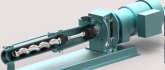
Using linear displacement sensors, a measuring device is placed at three points evenly fixed around the circumference on the screw. It allows measurements of nut displacement. In turn, an axial force is applied to the screw. All indicators of axial force F are located in Table 4.
Table 4. Values of axial force F when determining ball screw stiffness
| Size d0 x P, mm | F, kN | Size d0 x P, mm | F, kH |
| 16x2.5 | 0,5 | 50x10 | 3,75 |
| 25x5 | 1,6 | 50x12 | 6,9 |
| 25x10 | 3,0 | 63x10 | 7,5 |
| 32x5 | 2,3 | 80x10 | 9,15 |
| 32x10 | 2,5 | 80x20 | 12,0 |
| 40x5 | 4,6 | 100x10 | 15,0 |
| 40x6 | 3,0 | 100x20 | 25,95 |
| 40x10 | 3,25 | 125x20 | 40,0 |
| 50x5 | 4,85 | 125x20 | 40,0 |
Load capacity.
Table 5 shows the dynamic load capacity (Ca), statistical load capacity (C0a), minimum (Txx min) and maximum (Txx max) values of the no-load torque of ball screws.
Ball screws are characterized by a basic dynamic axial load capacity (Ca) and a basic statistical axial load capacity (C0a). In turn, C0a is the statistical axial force H, which causes general residual plastic deformation of the nut, grooves and ball. It is equal to 0.0001 of the diameter of the ball.
Table 5. Main characteristics of ball screws
| Size d0 x P, mm | Load capacity, N | Тхх, N m | ||
| static C0a | dynamic Ca | min | max | |
| 16x2.5 | 9600 | 5000 | 0,05 | 0,20 |
| 25x5 | 28100 | 16580 | 0,08 | 0,32 |
| 25x10 | 48800 | 46400 | 0,11 | 0,35 |
| 32x5 | 37500 | 17710 | 0,18 | 0,56 |
| 32x10 | 65000 | 49800 | 0,22 | 0,60 |
| 40x5 | 49400 | 19170 | 0,30 | 0,84 |
| 40x6 | 56400 | 23700 | 0,32 | 0,83 |
| 40x10 | 85900 | 54700 | 0,45 | 0,95 |
| 50x5 | 62800 | 20640 | 0,50 | 1,35 |
| 50x10 | 112500 | 57750 | 0,48 | 1,23 |
| 50x12 | 119900 | 65400 | 0,49 | 1,09 |
| 63x10 | 149700 | 62030 | 0,75 | 2,03 |
| 80x10 | 197700 | 66880 | 1,23 | 3,25 |
| 80x20 | 297600 | 143400 | 2,30 | 3,88 |
| 100x10 | 251100 | 71840 | 2,04 | 5,20 |
| 100x20 | 386400 | 151800 | 2,75 | 5,23 |
| 125x20 | 729000 | 278000 | 2,80 | 5,50 |
The basic statistical axial load capacity corresponds to a gear that is made of ordinary steel [1,3].
If the properties of the material differ from the usual ones, then in this case the value of the adjusted dynamic load capacity (Cap) and the adjusted static load capacity (C0ap) is calculated:
C0ap = K0С0а and Сap = KCa,
where K0 and K are correction factors.
The values in Tables 2-5 apply to 3-way ball screw nuts. If the number of nut contours is 1; 2; 4; 5; 6, then it is necessary to reduce the axial stiffness:
– for a static load capacity of 3; 1.5; 0.75; 0.6; 0.5 times (appropriate),
– for dynamic load capacity of 2.57; 1.42; 0.78; 0.64; 0.55 times (corresponding).
It is required that the critical axial force indicators comply with Industry Standard 2 N62-6-85.
Ball screw with preload.
Ball screws with preload are assembled to eliminate axial play in the screw-nut combination and increase the accuracy and rigidity of movement. Preload removes repeating screw pitch errors and aligns the position of the nut axis relative to the screw axis. Depending on the device, preload is performed by selecting a larger diameter of the balls or selecting two nuts (if the thread profile is semicircular), with further relative axial displacement, in one body. in the latter case, the housing and nut are connected by gear couplings. In such couplings, the internal teeth are cut on the body, and the external teeth are cut on the nut flanges.
Let us assume that the number of teeth on the flange of one nut is z, and on the flange of the other nut (z 1), then turning the nuts in one direction by the number of teeth k, at a step P, leads to their displacement along the axis:
Δ = Pk / [z(z 1)]
For example, if the number of teeth z = 92, nut rotation k = 1 and pitch P = 10 mm, then we have an axis displacement Δ = 1.2 µm.
The rotation of the nuts occurs on a specialized mandrel-pipe, outside the screw. The outer diameter of such a mandrel is usually equal to the inner diameter of the thread along the screw recesses. After this, the nuts are screwed onto the screw along with the housing.
Operating test and bearing strength test according to ISO 3408-3
Measuring the radial runout t5 of the outer diameter of the shaft on the segment l5 to determine straightness with respect to AA'
| Nominal diameter d0v mm | I5 | t5p in µm/interval I5 | ||||||
| accuracy class | ||||||||
| from | before | 0 | 1 | 3 | 5 | 7 | 10 | |
| 6 | 12 | 80 | 16 | 20 | 25 | 32 | 40 | 80 |
| 12 | 25 | 160 | ||||||
| 25 | 50 | 315 | ||||||
| 50 | 100 | 630 | ||||||
| 100 | 200 | 1250 | ||||||
| Nominal diameter I1/d0 | t5max in µm/I1>4*15 | ||||||
| From | before | 0 | 1 | 3 | 5 | 7 | 10 |
| — | 40 | 32 | 40 | 50 | 64 | 80 | 160 |
| 40 | 60 | 48 | 60 | 75 | 96 | 120 | 240 |
| 60 | 80 | 80 | 100 | 125 | 160 | 200 | 400 |
| 80 | 100 | 128 | 160 | 200 | 256 | 320 | 640 |
Measurement of radial runout t6.1 of the support journals in relation to AA' at l6≤l. For length l6>l the condition must be satisfied
| Nominal diameter d0v mm | l in mm | t6.1p in µm/interval l | ||||||
| accuracy class | ||||||||
| from | before | 1 | 3 | 5 | 7 | 10 | ||
| 6 | 20 | 80 | 10 | 12 | 20 | 40 | 63 | |
| 20 | 50 | 125 | 12 | 16 | 25 | 50 | 80 | |
| 50 | 125 | 200 | 16 | 20 | 32 | 63 | 100 | |
| 125 | 200 | 315 | — | 25 | 40 | 80 | 125 | |
Measurement of radial runout t7.1 of the screw end journals in relation to the support journals for l7≤l. Suitable for length l7>l
| Nominal diameter d0v mm | l in mm | t7.1p in µm/interval l | ||||||
| accuracy class | ||||||||
| from | before | 1 | 3 | 5 | 7 | 10 | ||
| 6 | 20 | 80 | 5 | 6 | 8 | 12 | 16 | |
| 20 | 50 | 125 | 6 | 8 | 10 | 16 | 20 | |
| 50 | 125 | 200 | 8 | 10 | 12 | 20 | 25 | |
| 125 | 200 | 315 | — | 12 | 16 | 25 | 32 | |
End run-out t8.1 of the shoulder of the propeller support pin relative to the support pin.
| Nominal diameter d0v mm | t8.1p in µm | |||||
| accuracy class | ||||||
| from | before | 1 | 3 | 5 | 7 | 10 |
| 6 | 63 | 3 | 4 | 5 | 6 | 10 |
| 63 | 125 | 4 | 5 | 6 | 8 | 12 |
| 125 | 200 | — | 6 | 8 | 10 | 16 |
Axial runout t9 of the nut bearing surface in relation to AA' (only for preloaded ball nuts)
| Flange diameter D2v mm | t9p in µm | ||||||
| accuracy class | |||||||
| from | before | 0 | 1 | 3 | 5 | 7 | 10 |
| 16 | 32 | 8 | 10 | 12 | 16 | 20 | — |
| 32 | 63 | 10 | 12 | 16 | 20 | 25 | — |
| 63 | 125 | 12 | 16 | 20 | 25 | 32 | — |
| 125 | 250 | 16 | 20 | 25 | 32 | 40 | — |
| 250 | 500 | — | — | 32 | 40 | 50 | — |
Radial runout t10p of the outer diameter of the nut in relation to AA' (only for ball nuts with preload)
| Flange diameter D2v mm | t10p in µm | ||||||
| accuracy class | |||||||
| from | before | 0 | 1 | 3 | 5 | 7 | 10 |
| 16 | 32 | 8 | 10 | 12 | 16 | 20 | — |
| 32 | 63 | 10 | 12 | 16 | 20 | 25 | — |
| 63 | 125 | 12 | 16 | 20 | 25 | 32 | — |
| 125 | 250 | 16 | 20 | 25 | 32 | 40 | — |
| 250 | 500 | — | — | 32 | 40 | 50 | — |
Changing the parallelism t11 of the cylindrical nut relative to AA' (only for preloaded ball nuts)
| t11p in µm per 100 mm (cumulative) accuracy class | |||||
| 0 | 1 | 3 | 5 | 7 | 10 |
| 14 | 16 | 20 | 25 | 32 | — |
The concept of accuracy class of ball screws
The general characteristic of ball screw accuracy, which is determined by the maximum errors of the instruments, is called their accuracy class. It is characterized by the following parameters:
- thread distance;
- geometric tolerance;
- level of surface smoothness;
- backlash;
- starting torque value;
- temperature operating conditions.
According to the production method, such transfers are:
- rolled. They are made by cold rolling, during which screw threads are made using special rolls. They belong to the transport group, since due to the graininess of the surface they allow movements that are not as smooth and accurate as precision pairs;
- polished. In such units, the screw grooves are hardened with multi-stage grinding. Used for high-precision devices. Belong to the precision group.
Precision rolling is also used, which involves a combination of both thread processing methods.
Depending on the application, there are 2 main groups of ball screws:
- transport (regular, with a gap). Such gears with low accuracy due to the presence of axial play are used for movements that are measured separately, without taking into account the angle of helical rotation. Examples: movements with low resistance (in door and valve drives), solving transport problems (in elevators), machine tools;
- positional (with interference, precision). Used when necessary to solve a high-precision problem. In this case, idling movement is not allowed. In such cases, transmissions require the presence of strong connections between nuts and assemblies. The dynamic load of the rod is reduced due to the strict dependence of screw speeds on nut movements.
Each of these groups has its own requirements, including accuracy class. Typically, positional gears have higher accuracy, while transport gears have a larger amount of backlash. Improve the performance of transport hubs with:
- creating preload. It involves applying a certain force to a pair to obtain the required level of axial rigidity. Helps reduce overall rod vibration and stabilize the nut axis in relation to the screw;
- increasing the diameter of the balls;
- using a double nut.
OST 2 R31-4-88 regulates the accuracy of ball screws in Russia, defining the following classes:
- for transport (T): T1, T3, T5, T7, T9, T10;
- for positional (P): P1, P3, P5, P7.
Foreign standards DIN 69051, Part 3 ISO 3408-3 provide for the following gear accuracy classes:
- for transport: C0, C1, C3, C5, C7, C10;
- for positional: C0, C1, C3, C5.
Tests for compliance with specifications 3408-3
Measuring the braking torque at the load Δ Tp
Braking torque via load Tpr
The ball screw torque required to turn the ball nut against the screw (or vice versa) without external load. Possible frictional moments due to the sealing element are not taken into account.
Total braking torque Tt
The torque required to turn a ball nut against a ball screw (or vice versa) without external load, including the frictional moment of the sealing elements
Torque Variation
Fluctuation value of a predetermined braking torque under preload. Positive or negative value relative to the average torque
Measurement method
Preload generates a dynamic friction torque between the nut and the threads in the ball screw. This is measured by moving the threaded spindle at a constant speed while the nut is held in place by a special locking device. The measured force F is used to calculate the braking torque of the threaded spindle.
| Average torque Tp0 [Nm] | Overall length [mm] | |||||||||||||
| Up to 4000 | From 4000 to 10000 | |||||||||||||
| 40 | (Thread length/screw diameter)≤40 | — | ||||||||||||
| ΔTpp (in % up to Tp0) accuracy class | ΔTpp (in % up to Tp0) accuracy class | ΔTpp (in % up to Tp0) accuracy class | ||||||||||||
| from | before | 0 | 1 | 3 | 5 | 7 | 0 | 1 | 3 | 5 | 7 | 3 | 5 | 7 |
| 0.2 | 0.4 | ± 30 % | ± 35 % | ± 40 % | ± 50 % | — | ± 40 % | ± 40 % | ± 50 % | ± 60 % | — | — | — | — |
| 0.4 | 0.6 | ± 25 % | ± 30 % | ± 35 % | ± 40 % | — | ± 35 % | ± 35 % | ± 40 % | ± 45 % | — | — | — | — |
| 0.6 | 1.0 | ± 20 % | ± 25 % | ± 30 % | ± 35 % | ± 40 % | ± 30 % | ± 30 % | ± 35 % | ± 40 % | ± 45 % | ± 40 % | ± 45 % | ± 50 % |
| 1.0 | 2.5 | ± 15 % | ± 20 % | ± 25 % | ± 30 % | ± 35 % | ± 25 % | ± 25 % | ± 30 % | ± 35 % | ± 40 % | ± 35 % | ± 40 % | ± 45 % |
| 2.5 | 6.3 | ± 10 % | ± 15 % | ± 20 % | ± 25 % | ± 30 % | ± 20 % | ± 20 % | ± 25 % | ± 30 % | ± 35 % | ± 30 % | ± 35 % | ± 40 % |
| 6.3 | 10 | — | — | ± 15 % | ± 20 % | ± 30 % | — | — | ± 20 % | ± 25 % | ± 35 % | ± 25 % | ± 30 % | ± 35 % |
Application areas of ball screws
Ball screw in a CNC machine
The relative simplicity of the design and the ability to manufacture a ball screw with various characteristics expands the scope of its application. Nowadays, ball screws are integral components of homemade milling machines with numerical control. Well, the scope of application is not limited to this.
Due to their versatility, ball screws can be installed not only in CNC machines. Smooth running and virtually zero friction make them indispensable components in precision measuring instruments, medical installations, and mechanical engineering. Often, spare parts from these devices are taken to complete homemade equipment.
This was made possible thanks to the following properties:
- minimizing friction losses;
- high load capacity factor with small design dimensions;
- low inertia. The movement of the body occurs simultaneously with the rotation of the screw;
- no noise and smooth running.
However, the disadvantages of ball screws for CNC equipment should also be taken into account. First of all, these include the complex design of the housing. Even if one of the components is slightly damaged, the ball screw will not be able to perform its function. There are also restrictions on the speed of rotation of the propeller. Exceeding this parameter may result in vibration.
To reduce the axial clearance, the assembly is performed with interference. To do this, balls of increased diameter or two nuts with axial displacement can be installed.
Axial clearance and interference
Through interference, the ball screw gap is eliminated and rigidity increases. Moreover, the positioning accuracy of the ball screw is also improved. The tension of a single nut is achieved by installing balls of selected sizes. Double nut tension is created by pulling two nuts against each other.
Table 1 Combination of axial clearance and interference
| Symbol | 0 | 1 | 2 | 3 | 4 |
| Axial clearance | Yes | No | No | No | No |
| Preload | No | No | easy | average | high |
| % of dynamic maximum permissible load | — | — | ~3 | ~5 | ~7 |
table 2
| C.I. | S.K. | S.C. | DC | S.U. | D.U. | S.E. | |
| 0 | * | * | * | * | * | * | * |
| 1 | * | * | * | * | * | * | * |
| 2 | * | * | * | * | * | ||
| 3 | * | * | |||||
| 4 | * | * |
Combination of axial clearance 0
Table 3
| Spindle diameter | Axial clearance of screwed ball screw |
| 04-14 | 0.05 |
| 15-40 | 0.08 |
| 50-100 | 0.12 |
Special ball screws
Ball screw performance continues to improve due to improvements in manufacturing methods and materials. New generation ball screws have higher load capacities, meaning they are increasingly being used for higher load applications as well as in more challenging environmental conditions. Consequently, the rise of ball screw drives is replacing traditional hydraulic drive methods in some high force applications.
New ball screw designs can also better withstand harsh conditions such as extreme temperatures, high particulate levels, exposure to chemicals and high-pressure washes, and shock and vibration.
With an increasing number of product options, engineers are looking for new tools and services to help simplify the ball screw selection process. Manufacturers offer sizing and product selection tools, as well as custom design services.
Critical ball screw rotation speed
Like any torsion shaft, the ball screw has a critical speed, which is harmonic oscillation. Constantly rotating the ball screw within the critical speed range will shorten the operating period and may affect the performance of the machine. The critical speed is a function of the ball screw diameter, length, and mounting configuration. The axial clearance of the nut does not affect the critical speed nk.
The operating speed should not exceed 80% of the critical speed. The formula below for calculating the permissible nkzyl speed takes into account this safety factor of 0.8.
,where Nk – critical speed (rpm) Nkzyl – operating rotation speed (rpm) α – safety factor (=0.8) E – elastic modulus (E=2.06*105 N/mm2) l – geometric moment of inertia (mm2) d2 – diameter of the ball screw rod (mm) γ – specific density of the material (7.6*10 -5 N/mm3) g – constant value of earth’s gravity (9.8*10 3 mm/s2) A – cross-section of the ball screw (mm2) lk – unsupported length between two bodies f – installation correction factor
| Floating – floating | λ=3.14 | f=9.7 |
| Hard - floating | λ=3.927 | f=15.1 |
| Hard - hard | λ=4.730 | f=21.9 |
| Hard - loose | λ=1.875 | f=3.4 |
The maximum permissible speed of the ball screw is limited.
For SC/DC nuts d0*nkzyl≤120 000
For CI, SK, SU/DU, SE nuts d0*nkzyl≤90 000, where d0 is the central diameter of the spindle, mm
Please contact our engineers if the required speed exceeds DN, or if the ball screw is used at higher speeds.
Permissible axial load for the propeller (longitudinal stability)
Like other screws, ball screws can withstand a limited axial load. If the load exceeds the maximum permissible values, this leads to damage to the screw. The permissible axial compression is a functional dependence of the length, diameter and type of mounting of the screw. The maximum compressive load should be 50% or less of the theoretically permissible load. The calculation using the formula below takes this safety factor into account.
, where Fk – theoretical maximum permissible axial load Fkzyl – maximum permissible working axial load α – Safety factor (=0.5) E – elasticity modulus ( E = 2.06*10 5 N/mm2) l – geometric moment of inertia l= d2 – diameter of the ball screw rod (mm) lk – length without support m,N factor associated with
| Floating - floating | m=5.1 | N=1 |
| Hard - floating | m=10.2 | N=2 |
| Hard - hard | m=20.3 | N=4 |
| Hard - loose | m=1.3 | N=0.25 |
Basics of calculation
Average rotation speed and average load
If speed and load vary, life calculations should be made using average values of Fm and nm
For the average rotation speed nm, in case of speed changes, the following formulas apply:
where nm is the average speed, q is the fraction of time
For the average load Fm, in case of load changes, the following formula is used:
, where Fm – average load q – fraction of stroke or time at constant speed
For average load Fm, if rotation speed and load change, the formula applies:
where Fm is the average load q is the fraction of time nm is the average speed.
Nominal life
Resource L, expressed in number of revolutions:
L – resource, Fm average load, Сa – dynamic load
Resource expressed in hours Lh
Lh – life in hours L – life in revolutions nm – average rotation speed (rpm) ED – operating time (%)
Motor driving torque and external force
Drive torque Mta To convert rotary motion into reciprocating motion:
Drive torque Mte for converting reciprocating motion into rotary motion
where Mta – drive torque (Nm) Mte – resistance moment (Nm) F – working load (kN) P – pitch (mm) η – efficiency (about 0.9) η' – efficiency (about 0.8)
When using double preload nuts, the idle torque must be taken into account:
Drive power Pa
Pa – drive power Mta – drive torque n – rotation speed
Ball screw drives (ballscrews). Basic theoretical information.
Material provided by the site "Designer's Handbook"
Ball screws (ball screws)
A ball screw (ball screw) consists of a screw and a nut and is used to convert rotational motion into linear motion. In the ball screw, screw 7 and nut 2 have helical grooves (threads) of a curved profile, which serve as raceways for balls placed between the turns of the screw and nut (Fig. 1). The most widely used threads are those with a semicircular profile. In this case, rotation of the nut secured against axial movements causes translational movement of the screw, or rotation of the screw secured against axial movements leads to translational movement of the nut. Basic geometric parameters of the transmission: nominal diameter d
0
,
i.e.
the diameter of the location of the centers of the rolling elements, the pitch P
of the thread and the diameter
D
ω of the rolling elements (usually
Dω = 0.6P).
The main advantages of a ball screw:
- the ability to create large axial forces;
- low friction losses (transmission efficiency 0.9 and above);
- the ability to obtain translational movement with high accuracy;
- small dimensions with high load-bearing capacity;
- significant resource.
The disadvantages include the complexity of the nut design, the need for high manufacturing precision and good protection of the transmission from contamination. Ball screws are used
in precision movement mechanisms, in tracking systems and in critical power transmissions (machine tools, robotics, aviation and space technology, nuclear energy, press-forging equipment, etc.).
Device and principle of operation.
When the screw rotates, the balls are drawn into motion along the screw grooves, progressively move the nut and, rolling out of the thread, return to their original position through the bypass channel (return channel).
Thus, the movement of the balls occurs along a closed circuit inside the nut. The most common ball screw design is one in which the return channel connects two adjacent turns.
Ball screw with preload.
In order to eliminate the axial gap in the screw-nut interface and thereby increase the axial rigidity and accuracy of movement of the driven element, the ball screw is assembled with
preload.
For a transmission with a semicircular thread profile, the interference is created by installing two nuts followed by their relative axial displacement. The relative displacement of the nuts is carried out by installing spacers between them or by their relative angular rotation. The thread profile and nut design (ball return channel, tension adjustment, etc.) are determined by the manufacturer.
ACCURACY STANDARDS
According to their accuracy parameters, ball screws are divided into positional and transport
(OST 2 R31-7-88). Positional ball screws allow indirect measurement of axial displacement depending on the angle of rotation and thread stroke of the screw. In transport ball screws, displacements are measured directly using a separate measuring system that does not depend on the angle of rotation of the screw. The kinematic and geometric accuracy classes of ball screws must comply with OST 2 RZ 1-4-88. According to this standard, accuracy classes are established for positional (P) and transport (T) ball screws, respectively: P1, PZ, P5, P7 and T1, TZ, T5, T7, T9. T10.
Kinematic accuracy
Ball screws are characterized by the kinematic error of the screw pair - the difference between the actual and nominal axial displacements of one of the mating parts of the screw pair in their relative motion.
The largest kinematic error is understood as the largest algebraic difference in the values of the kinematic error of the screw pair within a given length of axial movement. The dependence of the kinematic error of the screw pair on the nominal axial displacement is shown in Fig. 2. The deviation of the kinematic error over the entire measured length l
and thread should not exceed the permissible value
e
p
.
V
300r - width of the oscillation band of the kinematic error within 300 mm of the measured thread length;
V
2πр is the width of the deviation band of kinematic error pulsations within one revolution, i.e.
within the thread stroke P
h.
The permissible values of standardized indicators (Tables 5 and 6) are regulated by OST 2 RZ1-4-88, which takes into account ISO requirements.
5. Acceptable values of indicators V
300r and
V
2πr, mm
| Index | Accuracy class | |||||
| P1,T1 | PZ, TZ | P5.T5 | P7,T7 | T9 | T10 | |
| V 300rub | 0,006 | 0,012 | 0,023 | 0,052 | 0,100 | 0,210 |
| V 2πр | 0,004 | 0,006 | 0,008 | 0,012 | — | — |
MAIN CHARACTERISTICS OF BALL SCREWS
According to OST 2 R31-5-89, the quality of materials, processing and assembly of ball screws must comply with GOST 7599-82, and for export deliveries - OST2 N06-1-86. Radial clearance
between the screw and the nut before creating preload for a ball screw with a semicircular profile must correspond to the values given in the table. 8. Radial clearance is measured when the assembled nut is displaced in the radial direction under the influence of a force exceeding the gravity of the nut by 1.5-2 times. The measuring tip of the indicator should touch the outer surface of the nut.
8. Ball screw radial clearance before preload is created
| Nominal diameter d 0 | Thread pitch R , mm | Radial clearance, mm | |
| maximum | minimum | ||
| 16 | 2,5 | 0,020/- | 0,056/- |
| 25 | 5,0 | 0,093/0,107 | 0,067/0,073 |
| 25 | 10,0 | 0,170/0,170 | 0,110/0,113 |
| 32 | 5,0 | 0,096/0,110 | 0,064/0,075 |
| 32 | 10,0 | 0,170/0,171 | 0,110/0,112 |
| 40 | 5,0 | 0,096/0,110 | 0,064/0,072 |
| 40 | 6,0 | 0,101/0,113 | 0,059/0,065 |
| 40 | 10,0 | 0,161/0,173 | 0,119/0,126 |
| 50 | 5,0 | 0,101/0,110 | 0,059/0,061 |
| 50 | 10,0 | 0,163/0,175 | 0,117/0,125 |
| 50 | 12,0 | 0,183/0,197 | 0,137/0,146 |
| 63 | 10,0 | 0,165/0,177 | 0,115/0,123 |
| 80 | 10,0 | 0,167/0,179 | 0,113/0,121 |
| 80 | 20,0 | 0,247/0,273 | 0,193/0,211 |
| 100 | 10,0 | 0,170/0,192 | 0,110/0,118 |
| 100 | 20,0 | 0,250/0,276 | 0,180/0,198 |
| 125 | 20,0 | 0,422/0,430 | 0,338/0,350 |
Note. The denominator shows the radial clearance values for screws with relief grooves (Fig. 1.6). Axial rigidity.
Axial stiffness is understood as the ratio of the axial force applied to the nut group acting on the transmission to its axial movement relative to the screw, provided that the screw does not rotate.
The axial stiffness values must be no less than the values given in table. 9 and 10. When measuring stiffness, the body of the nut group and the screw are kept from turning. A measuring device is attached to the screw, allowing simultaneous measurements of the displacement of the housing (nut) relative to the screw at three points evenly spaced around the circumference using linear displacement sensors. An axial force F is applied to the screw.
The values of the force
F
applied to the screw when determining the axial stiffness are given in table.
11. Load capacity.
The values of dynamic
C
a and static
C
0a load capacities, as well as the minimum and maximum values of the ball screw idling moment
T
xx are given in table.
12. Ball screws are characterized by a basic static axial load capacity C
0a and a basic dynamic axial
C
a.
Basic static axial load capacity C
0a
is
the static axial force (N) that causes a total permanent plastic deformation of the ball, screw grooves and nut equal to 0.0001 times the ball diameter.
9. Axial rigidity of housing ball screws
| Nominal diameter d0 , mm | Thread pitch R, mm | Stiffness for accuracy classes, N/µm | |||||
| P1 T1 | PZ TZ | P5 T5 | P7 T7 | — T9 | — T10 | ||
| 25 32 | 5 5 | 500 700 | 460 650 | 420 590 | 400 560 | — | — |
| 40 | 5 6 10 | 950 830 740 | 880 770 680 | 800 705 620 | 760 660 590 | — — — | — — — |
| 50 | 5 10 12 | 1250 1000 900 | 1150 920 825 | 1050 840 750 | 990 800 705 | — — — | — — — |
| 63 | 10 | 1350 | 1260 | 1150 | 1100 | — | — |
| 80 | 10 20 | 1700 1450 | 1570 1360 | 1430 1240 | 1350 1180 | — — | — — |
| 100 | 10 20 | 2200 2100 | 2040 1950 | 1860 1780 | 1770 1700 | — — | — — |
Notes: 1. Stiffness for accuracy classes T9 and T10 is not regulated. 2. For versions with one nut, the rigidity is not regulated, for versions with two - according to the values given in the table (in this case, the nuts are enclosed in a technological housing).
10. Axial rigidity of frameless ball screws
| Nominal diameter d0 , mm | Thread pitch R, mm | Stiffness for accuracy classes, N/µm | |||||
| P1 T1 | PZ TZ | P5 T5 | P7 T7 | — T9 | — T10 | ||
| 16 | 2,5 | 230 | 215 | 200 | 190 | — | — |
| 25 | 5 10 | 560 460 | 540 440 | 490 400 | 460 380 | — — | — — |
| 32 | 5 10 | 760 610 | 730 590 | 665 535 | 630 500 | — — | — — |
| 40 | 5 10 | 1050 820 | 1000 780 | 950 715 | 900 680 | — — | — — |
| 50 | 5 10 | 1250 1100 | 1200 1050 | 1100 980 | 1050 930 | — — | — — |
| 63 | 10 | 1550 | 1500 | 1370 | 1300 | — | — |
| 80 | 10 20 | 1900 1650 | 1800 1580 | 1650 1440 | 1570 1370 | — — | — — |
| 100 | 10 20 | 2450 2350 | 2350 2250 | 2150 2075 | 2050 1970 | — — | — — |
| 125 | 20 | 2850 | 2750 | 2525 | 2400 | — | — |
Note. The rigidity for accuracy classes T9 and T10 is not regulated.
11. Values of axial force F
when determining the rigidity of a ball screw
| Size d 0 x P, mm | F , kN | Standard size d 0 x | F , kH |
| 16x2.5 | 0,5 | 50x10 | 3,75 |
| 25x5 | 1,6 | 50x12 | 6,9 |
| 25x10 | 3,0 | 63x10 | 7,5 |
| 32x5 | 2,3 | 80x10 | 9,15 |
| 32x10 | 2,5 | 80x20 | 12,0 |
| 40x5 | 4,6 | 100x10 | 15,0 |
| 40x6 | 3,0 | 100x20 | 25,95 |
| 40x10 | 3,25 | 125x20 | 40,0 |
| 50x5 | 4,85 |
12. Main characteristics of ball screws
| Size d 0 x P, mm | Load capacity, N | Тхх, N m | ||
| static C0a | dynamic Ca | min | max | |
| 16x2.5 | 9600 | 5000 | 0,05 | 0,20 |
| 25x5 | 28100 | 16580 | 0,08 | 0,32 |
| 25x10 | 48800 | 46400 | 0,11 | 0,35 |
| 32x5 | 37500 | 17710 | 0,18 | 0,56 |
| 32x10 | 65000 | 49800 | 0,22 | 0,60 |
| 40x5 | 49400 | 19170 | 0,30 | 0,84 |
| 40x6 | 56400 | 23700 | 0,32 | 0,83 |
| 40x10 | 85900 | 54700 | 0,45 | 0,95 |
| 50x5 | 62800 | 20640 | 0,50 | 1,35 |
| 50x10 | 112500 | 57750 | 0,48 | 1,23 |
| 50x12 | 119900 | 65400 | 0,49 | 1,09 |
| 63x10 | 149700 | 62030 | 0,75 | 2,03 |
| 80x10 | 197700 | 66880 | 1,23 | 3,25 |
| 80x20 | 297600 | 143400 | 2,30 | 3,88 |
| 100x10 | 251100 | 71840 | 2,04 | 5,20 |
| 100x20 | 386400 | 151800 | 2,75 | 5,23 |
| 125x20 | 729000 | 278000 | 2,80 | 5,50 |
Note. The given values for case ball screws correspond to versions II, III and IV. Basic dynamic axial load capacity Ca is the axial force (N) that the ball screw can support with a basic life of 1 million screw revolutions. Basic load capacities correspond to gears made of commonly used steels [1, 3]. If the properties of the material differ from the usual ones, and also depending on the accuracy class, hardness of the working surfaces, etc., the value of the corrected static C
0
ar
and adjusted dynamic
Car
load capacity:
С
0
ar =
K0
С
0
а
and
С ar = KСa,
where
Ko
and
K are
correction factors (see p. 798).
The idle torque is measured in a controlled gear installed in the centers of the stand, with the screw rotating at a frequency of 100 min-1. All parameters in table. 9-12 are indicated for ball screws with three-circuit nuts. For ball screws with nuts with the number of circuits 1, 2, 4, 5 or 6, the values of axial stiffness and static load capacity should be reduced by 3; 1.5; 0.75; 0.6 or 0.5 times respectively. The dynamic load ratings must be reduced by 2.57; 1.42; 0.78; 0.64 or 0.55 times respectively. In ball screws with liners installed in the nut windows using orientation elements that combine the return channel with the nut thread in the contact area of the balls with the nut, the dynamic load capacity is 1.02 times higher, and the durability is 1.06 times higher. The values of the critical axial force must comply with OST 2 N62-6-85. Ball screw with preload.
In order to eliminate the axial gap in the screw-nut interface and thereby increase the axial rigidity and accuracy of movement of the driven element, the ball screw is assembled with
preload.
Gears used in machine tool construction are carried out with interference;
they consist of two nuts, each of which has three working turns. Bypass channels in special liners connect two adjacent turns. The balls in this case are divided into three circulating groups. The thread profile is semicircular.
The tension is created by the relative axial displacement of the nuts, which is carried out
by installing spacers
between them or by their relative
angular rotation.
In the latter case, the connection of the nuts to the body is made using gear couplings, in which the outer teeth are cut on the flanges of the nuts, and the inner teeth are cut on the body.
The numbers of coupling teeth differ by one, which allows the nut to be rotated relative to one another by a small angle, causing an axial displacement of a very small amount. If the number of teeth on the flange of one of the nuts is z
, and on the flange of the other (
z
+1), then turning both nuts in one direction by
k
teeth leads at a step
P
to their axial displacement by Δ = Pk / [
z
(
z
+ 1) ] For example, with
z
=92,
P
=10 mm and
k
=1 we have Δ =1.2 µm. The nuts are turned outside the screw on a special mandrel - a pipe with an outer diameter equal to the inner diameter of the screw thread along the recesses, after which the nuts together with the body are screwed onto the screw.
TECHNICAL REQUIREMENTS
Technical requirements for the main parts of ball screws used in machine tool construction are established by OST 2 R31-5-89 (Table 13). Screw accuracy standards are according to OST2 R31-4-88.
13. Technical requirements for the main parts of the ball screw
| the name of detail | Material | Hardness of working surfaces HRCе, | Parameter Ra, µm, working surface roughness, no more |
| Screw | Steel 8ХФ GOST 5950-73 Steel 8ХФВД TU 3-213-84 | 59-63 | 0,63 |
| screw | Steel 9ХС GOST 5950-73 Steel ШХ15 GOST 801-78 | 59-63 | 0,63 |
| Earbuds | Steel 9ХС GOST 5950-73 Steel 40Х GOST 4543-71 Iron powder PZhV 3.160.24 GOST 9849-86 | 40-50 | 2,5 |
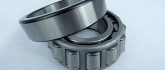
| Balloons | Steel ШХ 15 GOST 801-78 | 63-67 | 0,040 |
Notes: 1. Heat treatment according to RTM2 MT11-1-81. 2. For balls, accuracy level 20 according to GOST 3722-81. 3. The difference in size of the balls in one gear is no more than 0.001 mm 4. The deviation of the average diameter of the balls at D
ω < 5 mm – ±0.0025 mm;
2) D
ω ≥ 5 mm ±0.0050 mm Screws are also made from steel grades KhVG and 7G2VM with volumetric hardening, steel grade 8KhV with hardening by induction heating, steel grade 20KhZMVF with nitriding. For nuts, steel grade KhVG with volumetric hardening and case-hardened steel grades 18KhGT, 12KhNZA, 12Kh2N4A are used. The balls are made of chromium steel grade ШХ20СГ. The materials of the screw, nut and rolling elements must ensure the hardness of the working surfaces is not lower than 61 NKSe. During assembly, the nut cavity is filled with plastic lubricant brand CIATIM-201 or CIATIM-203. Transmissions require good protection against contamination. The most commonly used are harmonica-shaped bellows, telescopic casings and dirt removers - plastic sealing nuts with two or three convex turns along the profile of the grooves. Contaminant removers are attached to each end of the main nut.
NOMENCLATURE OF QUALITY INDICATORS
The range of quality indicators used in assessing the quality level of ball screws used in metal and woodworking machines, sections, lines, complexes, industrial robots and press-forging equipment is established by OST 2 RZ1-6-87. Classification groups.
The following groups of ball screws are distinguished: with preload;
without preload (gears with clearance). The nomenclature of product quality indicators, designations and characterized properties must correspond to those given in table. 14. The same table provides data on the applicability of ball screw quality indicators in scientific and technical documentation. The corresponding signs mean: “+” - applicability; “±”—limited applicability; “-”—inapplicability of the quality indicator. For gears with interference, indicators 1.4, 1.5, 1.7 and 1.11 are basic, indicator 1.10 is not used, indicators 1.3, 1.8, 1.9 and 1.12 have limited applicability. For gears with a gap, the main indicators are 1.4, 1.10, indicators 1.5-1.9, 1.11 are not used, indicator 1.3 has limited applicability. The range of quality indicators can be supplemented or modified by introducing other quality indicators that reflect design features or clarify the indicators given in Table. 14. Thus, the indicators of technical efficiency can be the indicators e
p,
V
ir,
V
zоor,
V
2πр of kinematic accuracy, characterizing the accuracy (instability) of positioning, and the indicator of economical use of energy is the efficiency
r\,
characterizing the efficiency of energy use.
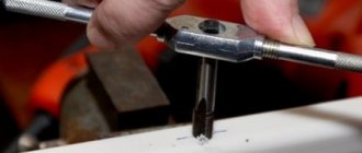
Mounting a nut on a screw
If ball screws and ball nuts are shipped separately, the screws must be installed by qualified personnel. Ball nuts must be mounted using a mandrel only. You can use the mandrel included with the ball screw. It is necessary to align the beginning of the screw thread to avoid damaging the seal and internal parts of the nut.
As standard, SNR ball screws are delivered with a nut installed. Dismantling the nut and spindle is not allowed (especially for preloaded nuts).
Note:
Ground ball screws with single or double nut are always shipped with the nut mounted, as are rolled screws with double nut.
Installation is carried out as follows:
Screw the nut onto the thread with light axial pressure. Then screw the nut down the entire length of the screw. Remove the mandrel only when the nut is completely screwed on. Secure the nut to prevent loosening. (use a rubber gasket or fix the support in the direction of the axis)
Important:
Use only original balls!
What to do, if…
Did the balls fly off while screwing the ball screw nut?
- Assemble the balls (the nut is only compatible with original balls) Loading power is ensured even when two or three balls are missing
- Carefully clean all components
- Use the mandrel as a mounting aid
- Put the balls back
- Start with the bottom stroke. Insert the balls into the circumference of the nut, the mandrel protects the balls from falling inside
Important:
Do not place idling balls between two baffles.
Ball screw operating conditions
The ball-bearing lead screw operates virtually without friction. The load between the screw and the nut is carried by ball bearings, which provide the only contact between the nut and the screw. The ball screw assembly will operate with either a nut rotating around a screw or a screw rotating through a nut. You can perform a simple functionality check in your business:
- Make sure the screw is clean and lightly oiled.
- Turn the nut around the fixed screw by hand. The nut should rotate smoothly, without jamming or freezing. Seizing should not be confused with balls that are compressed as they enter the raceway, passing under load between the nut and screw from the return system. Sticking or sticking (trapezoid) causes the balls to slip, form flat spots on the balls, and the nut eventually locks. In severe cases, the sliding balls can damage the raceways of the propeller and cannot be repaired.