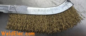
A simple and reliable carriage (broach) for an angle grinder
Materials and tools used by the author:
List of materials:
— square pipes of small diameter; — profile pipe 40X40 for the guide; — 8 bearings (used as rollers); - bolts and nuts; - a piece of round pipe; — 2 bearings for a hinge with a holder; - a few rods; - iron plates.
Homemade manufacturing process:
Step one. Preparing pipes for the carriage frame
First, we need to cut 4 pieces of profile pipe, their length must be exactly the same. We also measure each piece of pipe with a ruler for curvature. We either straighten a curved pipe or do not use it, otherwise the carriage will not work correctly. Next, we mark the locations and drill holes; they should all be drilled at right angles and in clearly defined locations. The author uses a drilling machine for drilling. Holes are needed for bolts that will tighten the entire structure and on which the bearings will be located.
At the end, we paint all 4 pieces of pipe well with a spray can so that the structure does not rust.
Step three. Carriage assembly
We assemble the carriage, here you will need bolts and nuts. As for the nuts, it is better to use those that have a plastic locking ring; such nuts will not unscrew themselves and the adjustment will not be lost.
Next, the carriage is adjusted on a profile square pipe measuring 40X40. However, you can completely adjust the carriage for a rectangular profile pipe. The most important thing is that the pipe is smooth, otherwise the cut will turn out crooked. You can also install a hinge unit on the prepared carriage axle; we clamp the bearings with a nut and washers.
We weld the prepared fastener through a piece of corner or plate to the carriage hinge. It is important that the angle grinder is fixed rigidly and that nothing springs; we strengthen the beam as much as possible with rods.
Step five. Assembly and testing
We assemble the carriage and fasten the profile pipe clearly horizontally. The homemade product is ready, the machine cuts perfectly, now it won’t be a problem to cut a sheet of metal straight. This is the end of the project, I hope you liked the homemade product and found useful thoughts for yourself. Good luck and creative inspiration if you decide to do this again. Don't forget to share your ideas and crafts with us!
Machine with shock absorbers
A reliable machine for a small grinder will be made from old car shock absorbers. The principle of its operation is similar to the pendulum, but the design of the components is different, which allows you to adjust the reach of the cutting power tool along the guide.
The manufacturing procedure is as follows:
- For the machine you need to find two old, but working shock absorbers from a passenger car.
- Shock absorbers have a weak point - the thin walls of the body. They cannot be a load-bearing structure, so brackets will need to be made. First, two identical plates are cut and holes are drilled in the center for a bolted connection. 8 half rings are cut out of a pipe whose diameter corresponds to the thickness of the shock absorber body. The blanks are welded against each other to the plates.
Making a stand for an angle grinder with your own hands
Angle grinders (angle grinders) are an indispensable hand tool. With their help you can saw, grind, cut almost any materials from wood to stone. But tasks often arise that require the use of machine tools.
For example, when cutting pipes, profiles or metal profiles, the task of cutting a long string into pieces of a certain length is quite common. In this case, it is important that the ends of the segments are strictly perpendicular to the center line.
When cutting ceramic tiles or bricks, it is even more difficult to maintain the perpendicularity of the cut while holding the grinder manually. When cutting thin and viscous material, the slightest deviation of the tool from the cut line can lead to jamming and breakage of the tool.
In such situations, it is quite natural to want not to buy a separate machine - this, as a rule, is not economically feasible.
You can expand the scope of use of your favorite hand tool by firmly securing it in some way.
Sheet steel cutting machine
Grinder machines, which can be used to cut steel sheet material, are much more complex than conventional pendulum ones.
The main difficulty here is that the sheet of metal has certain linear dimensions and it is necessary to maintain evenness of cutting along the entire line. Another difficulty here can be considered the effect of heating the cutting area, during which the metal expands and clamps the angle grinder disk in the channel, which is fraught with jamming and rupture of the tool with all the ensuing consequences. The main parts of such a machine:
- Base. Ideally, it should be no smaller than the sheet that is supposed to be cut with a grinder, or allow the entire cutting area to be laid on it. It is necessary to use steel as a manufacturing material so that it absorbs heat, preventing the steel cutting line from overheating.
- U-shaped stand. This structural element serves as a guide for pulling the angle grinder through. The length of the section between the legs of the stand should be sufficient to place a sheet between them, plus allow the body of the angle grinder to fit freely.
- The carriage is a movable element that moves along a U-shaped stand on bearings. A pendulum console and a depth limiter for lowering the cutting disc are attached to it.
- The pendulum console serves as a mechanism for lowering the angle grinder to the level of the working position. Also attached to it is a tool control handle.
You need to pull the angle grinder in the direction opposite to the direction of the sparks, otherwise the tool will be undermined with a high probability of jamming.
Materials and tools
The first question that a home craftsman faces when designing a stand for an angle grinder is what to make it from. The answer to this question is elementary: we will make what we have. If you have water pipes at hand, they will be useful for making hinges and guides. If there is a metal corner, we will assemble a frame from it.
The main and most complex component of a pendulum cutting saw is the hinge assembly. It bears the greatest loads, and the pendulum arm should not be able to deviate arbitrarily to the left or right. Please pay the greatest attention to the design of this unit. It is ideal to use roller bearings. Choose a couple of suitable sizes - and build the rest of the structure “around them”.
It is best to mount the pendulum arm on ball or roller bearings. This will ensure the best accuracy and rigidity. But if there are no suitable ready-made products, it is quite possible to look at options for homemade designs of this unit.
If there are no ready-made bearings, select pairs of metal tubes and steel pins of suitable diameters. This will allow you to make not very high-quality, but homemade bearings. For a “plywood” machine, good hanging hinges, used for fastening doors and gates, will work well as a suspension for the pendulum arm.
In any case, it is better to make the pendulum arm itself from a metal corner or a metal profile. But the holder in which the angle grinder will be fixed will probably be made of wooden beams.
For reliable and tight fixation of the grinder in the holder, it is better to cover the stock with soft and durable material. For example, leatherette. And it is most convenient to press the angle grinder to the holder with flexible metal ties with a screw assembly. These are widely used in plumbing and car service.
It is best to make the bed from a thick sheet of metal. Compromises are possible, up to thick plywood mounted on a frame made of wooden beams. It is good to provide on the work table the possibility of fastening the stop angles at some standard angles to the cutting axis. This way we get a “miter saw”.
Don’t forget that you won’t be able to control turning on the angle grinder on the machine in the usual way. We can replace the operator's hand on the control keys with the same screw ties for pipelines. But the key control station (which we will attach to the frame), a socket for connecting a fixed angle grinder to the circuit, and a wire with a plug of sufficient length to connect the entire machine to the network should be stored.
If we have metal blanks at our disposal, it is best to connect them by welding. If you do not have such an opportunity, it is better to turn to familiar masters of this business. Bolted connections become loose over time and negate all the advantages of a metal frame.
Of course, the grinder itself will come in handy when making the machine. Using it to cut blanks for a stand, you can feel like Munchausen, pulling yourself out of the swamp by your pigtail.
Assembly of a pendulum machine
The design of the pendulum machine consists of three main components:
- The bed is the simplest element of the machine for an angle grinder. The unit is made of a steel plate with a thickness of at least 10 mm with supports at the bottom. You can weld a frame from a profile pipe and sew 3 mm thick sheet metal on top. A bracket with a pendulum mechanism hinge is fixed to the frame.
- The pendulum is the main working mechanism of the machine. The structure in the shape of the letter “T” is welded from a profile pipe. A clamp for an angle grinder is fixed to one end, and the other side of the pendulum is attached to the hinge mechanism.
- The clamp for the grinder is made of metal brackets. The structure is firmly fixed to the pendulum through the console.
To make a machine, you will need a drawing or at least a simple diagram. One of the options is shown in the photo. The dimensions of the machine will have to be calculated according to the dimensions of the available grinder.
To correctly calculate the size of the machine components, first measure the dimensions of the angle grinder, and then the distance between the holes on the gearbox housing. When designing a pendulum, it is important to reduce the distance between the cutting disc of the grinder and the hinge mechanism to a minimum. This will stiffen the machine, allowing for smoother cuts.
After developing the drawing, we begin manufacturing all machine components:
- According to the dimensions of the diagram, metal blanks for all components are cut. First, the frame is made. It is necessary to take into account that during the cutting, the grinder disk will be buried in the slot of the slab. If you weld a rectangular frame from a profile for the bed, and sew a steel sheet on top, then a niche will form below. There will be enough space for the cutting disc to enter. When making a frame in the form of a plate of steel 10 mm thick, you need to weld supports from below.
- Next, we begin to manufacture the pendulum. An axle for the swivel bearings is welded to the end of the profile pipe workpiece. On the other side of the pendulum you need to make a clamp for the grinder. To do this, a bracket is bent from a steel strip in the shape of the letter “P”. The grinder gearbox should fit into it. Holes for bolted connections are drilled in the side shelves of the bracket.
- The second part of the clamp is bent from a steel rod. You should get a clamp in the shape of the letter “P”, into which the body of the angle grinder fits. A thread is cut at both ends of the clamp. The clamping strip is cut from a steel strip 5 mm thick. Holes are drilled along the edges of the strip at such a distance that the threaded ends of the clamp fit into them.
- Both U-shaped fastenings, that is, the clamp and the bracket, are fixed to the console. The part is a rectangular steel plate, which, together with the clamps for the angle grinder, is subsequently secured to the second end of the pendulum.
- The next step is assembling the hinge. Two bearings are mounted on a shaft welded to the pendulum. Nests for them can be made from a piece of pipe of the appropriate diameter. The cut rings are placed on the bearing races. Now this unit must be secured to the frame.
- The sockets will only have to be welded to the plate without removing the bearings. The knot is placed at a distance of 5–6 cm from the edge of the bed. During welding, the bearings are covered with a wet cloth or watered to avoid overheating.
- The pendulum lever with the hinge is ready. Now it’s time to secure the console with clamps to its second end. The grinder itself can be fixed on the pendulum so that the rotation of the disk is carried out “from itself” or “toward itself”. Here each master chooses at his own discretion.
- To prevent the pendulum and angle grinder from lowering arbitrarily, a return spring is provided. It should act in tension and be very elastic. The spring is secured with loops welded to the frame and pendulum.
- The machine is almost ready. All that remains is to make a slot in the plate for the disk to enter. You don't even need to measure anything here. The grinder clamped in the pendulum is turned on and the slab is cut with a cutting disc. Initially the slot will be thin. To expand it, a thick disk is placed on the grinder, and then the procedure is repeated.
While making a slot on the bed, a test of the machine occurred. The only thing missing is the last component – the clamp for the workpieces. There are many options here. You can simply attach small pieces of wood to the stove. As an option, a stop is welded from a piece of profile pipe onto the frame, and a nut and screw are fixed opposite it. It turns out to be a good screw clamp. If you fasten a metal ruler on top of the stop bar, it will be convenient to cut the workpiece to the required size.
Universal carriage for angle grinders and other tools
In this review, the author shows how to make with your own hands a universal carriage for an angle grinder (angle grinder) with a saw or cutting blade and other tools: a knife and a glass cutter.
To make this homemade device you will need: bolts and nuts, bearings, a profile pipe of square and rectangular cross-section, a metal strip and some other parts.
First of all, the author cuts four pieces of square profile pipe from which the carriage will be made. Holes must be drilled in the blanks at the marked locations.
The author welds nuts to two of the four blanks, as well as to a piece of profile pipe of rectangular cross-section, having previously welded them together.
Step-by-step instruction
So, the design details and the necessary tools have been selected, you can begin assembling and subsequent installation of the homemade carriage.
Step 1: Attaching the aluminum profiles
Since the carriage will “run along the saw table,” the first thing to do is guide grooves. To do this, take two U-shaped profiles, approximately equal to the length of the table. You can adjust the dimensions using a grinder.
At the same distance from the location of the cutting disc, circular saws draw two lines parallel to it. Then, using a hand router, U-profile holes are cut out along them, chips are blown out of them, and the corrugated pipes are secured in them using glue. After the glue dries, the grooves are ready.
Step 2: Making the carriage base
Next, the mobile base of the cross-cutting carriage is constructed. To do this, take two strips, which in thickness fit freely into the U-shaped groove. But there is one point here - the carriage will have to “slide” freely on the table, and for this it is raised above the table by 2-3 mm. To do this, nuts of equal thickness are placed into the profile grooves at equal distances, after which guide rails are laid on them.
Copying materials
The use of any materials posted on the Labuda.blog website is permitted only if you provide a direct indexed link (hyperlink) to the copied page of the Labuda.blog website. A link is required regardless of the full or partial use of materials.
ATTENTION! We do not allow third-party resources to embed links to image files hosted on our hosting. All images are protected from hotlinking. Regular copying (saving) of images to third-party resources is permitted!
legal information
Dear authors, remember that the publications you post must not violate the laws of the Russian Federation and the copyrights of third-party resources.
* Extremist and terrorist organizations banned in the Russian Federation and the Republics of Novorossiya: “Right Sector”, “Ukrainian Insurgent Army” (UPA), “ISIS”, “Jabhat Fatah al-Sham” (formerly “Jabhat al-Nusra”, “Jabhat al-Nusra"), National Bolshevik Party (NBP), Al-Qaeda, UNA-UNSO, Taliban, Majlis of the Crimean Tatar People, Jehovah's Witnesses, Misanthropic Division, Brotherhood "Korchinsky, "Art preparation", "Trident named after. Stepan Bandera", "NSO", "Slavic Union", "Format-18", "Hizb ut-Tahrir".
Device for accurately cutting metal
A 1300-watt grinder mounted on a homemade guide using bearings. They move along a 40 x 40 square that acts as a rail. It turned out 7 pieces. I fixed it on the rail on 4 sides, 2 between them, and one at the bottom moves along the plane. I installed the angle grinder on the guide using a fastener and secured it with a handle. On the other side with a bolt. There are slots here, you can choose the height of the disc.
There is a small nuance.
To get a high-quality cut and avoid the disc biting, you need to align the angle grinder and disc very evenly vertically. The side fastenings are not enough for this, because the angle grinder slightly changes its position to the right or left when loaded. To do this, the master did the following. To prevent this from happening, there are holes in the lid of the grinder, exactly the same for the handle. I screwed a bolt into it and secured it with a nut. I drilled an exactly parallel hole in the plate, screwed in a bolt, and secured it with a nut on both sides. Set it to a straight, vertical position. Tightened two nuts on both sides. Added a lower bearing. The height was already known after fixation. Got four points. The angle grinder is installed very firmly and tightly; there are no backlashes or swings when moving. This allows you to cut thick metal - five, six.
In terms of safety, I added a cover, since the front side of the disk is located towards the worker. If you come across a disc of poor quality, or it gets bitten, so that even if it shatters, the fragments do not fall on a person, add protection. I screwed it to the original one.
There were no problems with replacing the disk; the distance allows you to insert a key, unscrew the nut, and change it. Added a top rail. For what? It happens during operation that the disk bites or gets stuck. Since the revolutions are high, the entire structure together with the angle grinder can fly off the bottom rail. To prevent this from happening, I added this rail. The height is adjusted with a bolt. For smooth running, I added bearings on both sides.
Next, watch the video from the fifth minute.
Vadim Ivanov.
Guide for smooth cutting angle grinders
Let's make a simple device for an angle grinder. I had an idea in my head for a long time and decided to bring it to life. The device is simple, so you will need a minimum of materials. The first and most important thing is the grinder itself. The author of the homemade product uses a battery, but it turned out to be weak. Therefore, he recommends a regular 220 volt one. A piece of profile pipe 40 by 60 millimeters and a length of 150 and a profile pipe with sides of 25 millimeters. The length can be adjusted to suit your needs. For example, I decided that a piece 1 meter long was enough.
Let's start with the markings. From a 40 by 60 pipe you need to cut a corner with sides 50 by 35 millimeters. Cut out the rest of the pipe. We cut two more strips 25 and 20 millimeters wide. When all the workpieces are made, we move on to welding. We wrap the profile pipe with a sheet of paper to make gaps between the parts to be welded and the pipe. We display all the blanks as shown in the video. We clamp with clamps and grab. You can scald everything and sand the seams. We got the detail.
This is a tire with a carriage for smooth cuts of sheet metal and more. We will attach the carriages. I'll weld two strips of metal with holes for fastenings. It’s better to weld in place, so we screw the strips to the patient and grab them. And then you can paint it. We install the helmet and move on to the tests. We will cut a piece of 3mm metal. I secured the guide bar with two clamps.
The device works. I regretted installing the carriage on a cordless angle grinder. It is much weaker than the network one. Most likely, we will later convert the carriage into a network one with a 125 mm disk. An even cut is obtained using a device.
Preparing for work
You need to prepare for the work so that it doesn’t turn out that when you get to half of all the work, it turns out that something has been forgotten, missed or missing. Therefore, we recommend that you first read the material in this article and check the availability of all the necessary materials, tools and technological equipment. For this purpose, when describing the manufacturing process, everything is described in detail and broken down into operations.
Tool
To make a wood lathe from a drill, you will need the following tool:
- Sawing machine or circular saw.
- Jigsaw.
- Grinder (if correct, then an angle grinder (angle grinder).
- Screwdriver or drill.
- Grinding machine.
- Hand tools: clamps, screwdriver, hammer, square, marking pencil, etc.
Material and components
To make a woodworking machine with your own hands, you will need the following materials and components:
- Plywood 15 mm.
- Pine massif;
- Wing nut;
- Fastening: M6 bolt, self-tapping screws of various lengths.
Main structural elements
The design of a homemade lathe based on a drill consists of the following parts:
- Base:
- Frame;
- Spindle box;
- Headstock and tailstock;
- Tool rest with carriage;
- Drill.
Selecting material for the bed
In this case, the capabilities of the angle grinder are significantly expanded. By installing the grinder on a stationary structure, you can make a cutting machine that will accurately and at the desired angle cut any profiles - angles, I-beams, metal pipes.
To cut metal, wood, and plastic sheets of large sizes, you should install the grinder on a moving carriage moving along guides. In this case, it is advisable to use metal corners as guides.
Stand for grinder
The angle grinder stand comes in a variety of designs. A variety of materials and components can be used for its manufacture. It makes no sense to recommend a specific design, since each owner of an angle grinder will adapt the angle grinder to his own requirements.
Profiled pipes can be used as starting materials for the device, as they are the most durable and reliable for this type of work. For guides, you can use corners, 5U or 6.5U channels.
For complex structures you will need a welding machine, but it is easier to get by with screw connections. If the work does not require special precision, then the grinder can be used simply as a portable tool.
To perform precise work, for example, with a grinding attachment, you may need a stationary device - a stand for an angle grinder (you can assemble a simple collapsible machine with your own hands, which after use will be folded and hidden in the designated place). Such a frame is sometimes also made of wood. It is advisable to make a wooden frame if frequent and prolonged use of an angle grinder is not expected.
Construction of cutting machines
When designing a homemade cutting machine from an angle grinder, the following factors should be taken into account :
- The bed, or base, must be strong enough, stable, and heavy. For reliability, it must be attached to a workbench or table.
- Cutting equipment must be positioned strictly perpendicular to the base.
- The cutting wheel feed mechanism is equipped with a return spring or counterweight to prevent damage to the abrasive disc.
- For convenience and safety of work, the design is equipped with a handle. The best option would be if the angle grinder can be lowered by the standard handle.
- The protective cover prevents sparks from entering the worker.
- Clamping device. Securing the workpiece is a necessary requirement for obtaining a quality cut.
- If you plan to cut a large number of workpieces of the same size, then the design can be equipped with a movable stop.
- Starting device or emergency shutdown. Constantly turning on the grinder with a standard switch is inconvenient. And specialized starting devices have internal protection.
Miter box from a grinder
If you turn the tabletop under an angle grinder, you will get an excellent miter box. Using such a device, you can quickly cut a plinth, baguette, or profile from any material at a fixed angle.
One has only to install the appropriate disk, fix the tabletop at an angle of 45 degrees - and cutting trim for the windows of a wooden house turns into a pleasure.
With this machine you can easily cut paving slabs diagonally, diversifying the ways of laying them.
Something similar is also available in an industrial version, but the cost of such devices will scare off not only the home craftsman, but also a small team of mechanics.
What may be needed to make a bed
Drawing of a metal frame
Before you start making a frame for an angle grinder, you should decide what types of work this machine will perform. A self-made angle grinder stand can be much more functional than industrial products. The type of attachment of the angle grinder to the frame is of great importance - vertical or horizontal. The depth of cut largely depends on this. The type of fastening also depends on the nature of the work performed.
To cut materials on a stationary work table, the grinder is mounted on a pendulum bracket made of angles or profiled pipes. If it is necessary to cut large sheets of steel, textolite, or plywood, then the angle grinder is mounted on a movable carriage that moves along guides made of angles or channels. Having decided on the design, you should prepare the necessary tools and materials in advance.
- Bulgarian;
- drilling machine;
- welding machine;
- grinding wheel;
- pliers;
- Screwdriver Set;
- a set of keys;
- measuring instruments.
- steel corner 40×40;
- steel corner 50×50;
- channel 5U or 6.5U (for guides of a moving carriage);
- water pipe cuttings;
- profile pipes 15×15, 20×20, 25×25;
- bearings;
- hardware;
- tin trim;
- textolite
Making a lathe
To describe the entire process of creating a wood lathe with your own hands, we will highlight several stages and group the work by structural elements. This description will contain photos and video materials.
Base (frame and spindle box)
As mentioned above, part of the structure was used from the previously described drilling machine. Therefore, in this material we will not do this again, and simply suggest opening the article “Homemade drilling machine from a drill (screwdriver). Description, drawings, video. “- everything is described in detail there.
Thus, we believe that the frame and spindle box are ready and look like this.
Headstock and tailstock
Both headstocks are power elements, so they will require greater strength. To ensure this, it is necessary to glue not even two, but three layers of plywood for one workpiece. The overall dimensions of both headstocks are 120 x 160 mm.
Next, you need to give the required shape to the blanks to get full-fledged parts. Drawings of all parts are collected in the section “Conclusion / Drawings of blanks”. This can be done either on a circular saw or on any other sawing machine. The end result is details like these.
Nozzle for connecting to a vacuum cleaner
This simple device will help you protect your respiratory system from dust while cutting wood, metal and other materials. The nozzle is installed on the cutting part of the grinder, covering it completely. A special pipe provides connection to a vacuum cleaner hose, which allows you to remove dust quickly and efficiently.
Dust grabber
Thanks to its special design, the device ensures removal of 99% of dust. The attachment is easy to install and compatible with most power tools. The transparent body provides good visibility of the work area. This device supports cutting depth adjustment.
Buy a dust extractor on Aliexpress
Bench Grinder
The stationary grinding machine can be made from an angle grinder in two versions.
In the first case, the grinder is fixed motionless on a special device. And another manufacturing option is shown in the figure. In the second case, it is a belt-type grinding machine. It is shown in the picture. Here it is necessary to consider the tensioning mechanisms (on 2 or 3 rollers) and fastening to the tabletop.
How to make a simple angle grinder stand with your own hands
Using the most common tools and using available materials, you can make a simple stand for an angle grinder with your own hands. To secure the grinder to the frame, you will need corners, metal or textolite plates. If two metal plates are used, you can replace the screws with a welded joint. The plate, which serves as a mobile platform, is made of steel sheet or duralumin up to five millimeters thick.
Homemade stand for angle grinder
If you use textolite instead of a metal sheet, then the workpiece should be up to ten millimeters thick. The second plate must be metal, as it serves as a stop. For manufacturing, steel five millimeters thick is used, since the main load is applied to it. Thinner metal cannot be used due to vibrations and possible deformation, which makes working with the device unsafe.
For reliable fixation on the platform, several through holes with a diameter of five millimeters are drilled on one half of the plate. The second half of the plate is marked so that a hole with a diameter of eight millimeters can be drilled in its center. All holes drilled in the platform are drilled from the back for countersunk screw heads. It is possible to install a corner instead of the second plate, drilling it accordingly.
If welding cannot be used, the corner or plate is firmly secured with screws to the platform so that the distance from the edge of the device to the cutting disc is at least five millimeters. The corner should be bent in relation to the stand by 60°. To prevent the bolt from turning and vibration, the angle grinder is fixed in the upper part with a bolt with a Grover washer or a lock nut.
Step-by-step instruction
So, the design details and the necessary tools have been selected, you can begin assembling and subsequent installation of the homemade carriage.
Step 1: Attaching the aluminum profiles
Since the carriage will “run along the saw table,” the first thing to do is guide grooves. To do this, take two U-shaped profiles, approximately equal to the length of the table. You can adjust the dimensions using a grinder.
At the same distance from the location of the cutting disc, circular saws draw two lines parallel to it. Then, using a hand router, U-profile holes are cut out along them, chips are blown out of them, and the corrugated pipes are secured in them using glue. After the glue dries, the grooves are ready.
Step 2: Making the carriage base
Next, the mobile base of the cross-cutting carriage is constructed. To do this, take two strips, which in thickness fit freely into the U-shaped groove. But there is one point here - the carriage will have to “slide” freely on the table, and for this it is raised above the table by 2-3 mm. To do this, nuts of equal thickness are placed into the profile grooves at equal distances, after which guide rails are laid on them.
Then glue is applied to them, which fixes the plywood base strip. To press it tighter, you can attach clamps on the sides.
When the resin has dried, the nuts are removed from the profile grooves and the master checks whether the carriage moves freely on them. After this, for ease of further use, the carriage is cut off on the sides along the table profile.
Step 3: Installation of walls
So, the base is ready and then the thrust walls are installed on it. To do this, take two wooden blocks: one of them is rigidly fixed, using self-tapping screws, along the edge closest to the master so that it is strictly perpendicular to the cutting edge of the saw blade; the second is secured along the top edge, but only on one side. This is necessary so that the master can align this wall strictly parallel to the bottom. The operation is performed using a square.
After the walls are leveled, a test cut is carried out. It has two purposes - it is used to saw holes in the walls and base of the carriage, and then by measuring the sawn workpiece, they check whether the right angle of the cut is correct.
Important . The height of the walls must be sufficient so that the cutting edge enters no more than half of it, otherwise the carriage may break during operation - and this is an unjustified risk when working with a circular saw.
Step 4: Making a Combination Square for Miter Cutting
So, a regular straight broach carriage is ready, but what if the cutter needs to cut something at a different angle, such as 60, 40 or 30 degrees? For such operations, you will need an additional structural element, which is called a “combined square”.
The name is put in quotation marks for a reason - the fact is that the base of the workpiece is really a square wooden platform. It is cut out so that it fits freely between the stops of the main carriage and one of the sides is fixed at the bottom wall.
Belt sander
Using this attachment, you will get a full-fledged grinder based on a standard grinder. This device is much more practical and convenient than conventional grinding discs. The main advantage of this nozzle is the elongated working part, which allows you to grind surfaces even in hard-to-reach places (for example, in slots in furniture). This is facilitated by the ribbon adapter.
Tape adapter
The nozzle is easy to connect (takes 1 minute). Threaded spindle - M10 and M14. The working head rotates at an angle of 180 degrees, simplifying grinding. The ergonomic design makes surface treatment quick and enjoyable.