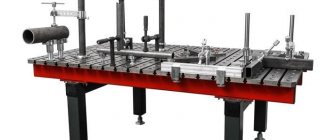
To increase productivity, as well as achieve increased equipment efficiency, a special rotary table is installed for the milling machine. This addition will help you easily work with large and small parts.
Today, the most important part for metalworking is the rotary table for a CNC milling machine. The concept of CNC is not familiar to all craftsmen; it means that the machine is equipped with numerical control. With its help, the unit easily switches to mechanized processing in offline mode. The presence of a specialist is necessary only during control measurements.
Milling machine table
The rigidity of the equipment itself depends on this part, and this is important during the milling process. The basic function of the rotary table of a CNC milling machine is convenient attachment of equipment for further processing of parts.
Rotary table for CNC milling work
The most important indicator of a device is its area; the ability to install parts of various sizes depends on it. The larger the working area of the rotary table for a milling machine, the greater its versatility.
In other words, if the product is small in size, it is very easy to fix it on a large surface. But a large part cannot be installed on a small rotating mechanism. The multifunctional installation solves such problems in a matter of seconds. To fully work with a modern unit, you need to carefully study the instructions, as well as try out different parts in operation.
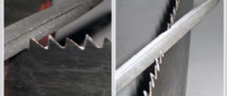
Another positive quality of a large device is the ability to cut blanks. As a result, the manufacturability of milling equipment increases. There is no need to install special additional systems for these purposes.
The movable device of the unit must have a protective coating made of different materials, for example, plastic.
The design of such a mechanism must have high strength and be very rigid. Thus, the vibration that occurs during milling is dampened.
What you need
In order to make a cake turntable with your own hands, you will need:
- Bearings - 2 pcs. It is better to use double pressed bearings.
- Wooden blank for a circle. This could be a door from old furniture or any chipboard material available.
- Nails.
- Self-tapping screws.
- Tube (plastic or iron).
- Circle made of iron (metal).
- Plywood sheet.
- Plastic or decorative self-adhesive film.
Types of additional equipment
The design of such tables differs in many ways:
- They can move in different planes, for example, a mechanism that can move horizontally and simultaneously rise vertically makes it possible to perform circular milling when it is necessary to make helical grooves in a part.
- The mechanism, capable of tilting at different angles, allows processing of steel parts installed on the surface at a certain angle. There is no need to constantly reposition the workpiece; simply rotate the table surface and lock it in the desired position.
- In such milling devices, special disks are installed that break the surface of the device into working areas. The horizontal plane is considered simple; it is used in small compact installations and allows you to perform various milling operations.
Thanks to the rotating mechanism, it is easy to process the corners of the workpiece, make grooves and mill ledges.
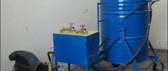
There are also special vacuum systems available in several versions.
Vacuum pump for vacuum pressing of sheet materials
The part is pressed against the surface of the turntable by a special vacuum mechanism, which fixes it in a certain position. The reliability of such a device is very high, the part does not move during operation, is not damaged, and does not go out of the master’s visibility zone.
How does the rotary system work?
The operating principle of such a mechanism on a CNC milling machine, as well as any other milling equipment, does not have any fundamental differences. The main details are:
- The base is very reminiscent of a bed, equipped with a mechanism for fixing to the surface of the machine.
- Control - to ensure rotation of the faceplate around its axis, an electric motor is installed. The latest CNC milling systems, on which such mechanisms are installed, differ in their design; they work according to a specially specified program.
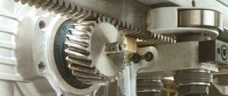
- The faceplate plays the role of a rotating mechanism and is equipped with a reliable fixation. There is a hole in the middle in the form of a Morse cone. The working plane is equipped with T-shaped grooves; clamps are inserted into them to secure the workpiece being processed.
Faceplate
A rotary table mounted on the base of the machine makes it possible to process parts simultaneously in several planes:
- vertical;
- transverse;
- longitudinal
Any milling mechanism equipped with such a system has the ability to move in different planes. This helps create the necessary slope for the workpiece. For example, machines equipped with CNC make it possible to process parts with a spiral configuration.
If control is performed manually, the device carries out various transitions, rounding parts, milling curved surfaces. This approach to work allows you to increase the efficiency of the unit tenfold, as well as simplify the work performed by half.
Milling work on a rotary table
About the turntable, or relay logic through the eyes of an amateur
Some friends once asked me to help with programming a turntable controller for photography. These tables are used for circular shooting. Often the result of such photography can be seen in online stores, when the product can be twisted and viewed from different angles.
How to take a 360° photo? You can place an object on a turntable, then manually move it to a certain angle and click the camera shutter. But it is better to automate this process.
My friends have been involved in this business for a long time; they themselves develop and make automated rotary tables of various sizes based on a stepper motor with a controller. Previously, they used a controller running under computer control. Then production of these controllers ceased, and it was necessary to write a program for a new stand-alone controller.
This is a completely new matter for me. I have never worked on automated control systems, I am unfamiliar with relay logic, and I have never heard of PLCs. Well, the more interesting it will be to understand what relay logic is and what the LD (Ladder Diagram) and IL (Instruction List) languages are.
Here's what you can get with a turntable:
And here is the turntable itself:
And this is the SMSD‑1.5Modbus controller. By the way, it’s a domestic development. However, in its place there could be any other PLC:
The controller comes with software. Both programming languages LD and IL are used. I'll tell you a little about ladder diagrams. Here are the main elements of the LD language:
| input signal, normally open contact |
| input signal, normally closed contact |
| output, coil |
Input contacts are designated by the letter X with a number. A normally open contact is activated when a signal is applied to the input. The normally closed contact is normally closed and operates when the input signal is lost.
Input contacts can be combined. This is a logical AND:
And this is a logical OR:
Output contacts are designated by the letter Y followed by a number. There are other symbols:
| Symbol for pulse input signal with rising edge polling |
| Symbol for pulse input signal with falling edge polling |
| Symbol for application instructions |
| Logical inversion symbol |
Here is an example of a simple diagram. When contact X1 is closed, we start the engine and set output Y0. The corresponding LED light on the controller panel will light up:
Here's a more interesting case:
Here, when contact X5 is closed, output Y3 will change its state to closed, however, when contact X5 is opened, output Y3 will retain its closed state until input X6 is turned on. Contact Y3 is self-latching.
Ladder diagram language is derived from the ladder circuit diagram in a simplified representation. For comparison, here is a ladder circuit and the corresponding LD diagram:
The controller essentially emulates the operation of a relay circuit. And this circuit is described by a program that is loaded into the controller. In a real relay contact electrical circuit, all specified control processes are executed simultaneously (in parallel). Each change in the state of the input signals immediately affects the change in the state of the output signals.
In the controller, a change in the state of the input signals that occurred during the current program pass is recognized only at the next program cycle. This controller disadvantage is mitigated by the short cycle time. The execution time of one program cycle depends on the number of executed instructions in the program and on the type of instructions used. While working on the program, it turned out that time depends on something else, but more on that later.
During operation, the controller continuously polls the current state of the inputs and changes the state of the outputs depending on the user program. At the first stage, the state of the physical and virtual Modbus Coils inputs is read and buffered in the internal memory of the controller. Yes, the controller can also be controlled via the Modbus protocol, but since I used it autonomously, I will not talk about Modbus.
At the second stage, the state of the buffered inputs is processed and the state of the outputs in the controller memory changes according to a given user program. At the third stage, the controller changes the state of the physical and virtual outputs.
An IL program consists of a sequence of individual control instructions. The controller processes instructions sequentially, one after another. Actually, it is the sequence of instructions with operands that is loaded into the controller. There are a lot of instructions. There are commands for checking input conditions, there are arithmetic, bit and logical commands, integer arithmetic and floating point arithmetic are possible. It is possible to use interrupts and subroutines. Finally, there is a group of commands for motor control.
The operands are registers (general purpose, non-volatile and index), markers (one-bit memory cells), timers, counters and constants.
We can consider the controller to be tens or hundreds of individual relays, counters, timers and memory. All these registers, counters, timers do not physically exist, but are simulated by the processor.
This picture shows an LD diagram and the corresponding IL program:
IL is very similar in appearance to assembler. There is a fixed set of instructions; instructions can have one or more operands. This is what misled me. At first, I generally imagined that the IL program was translated into assembler and then executed in the controller. It turned out that this was not the case. The commands, together with the operands, are translated into an internal format and processed at each cycle by the runtime environment, that is, by the controller firmware.
It was somewhat of a surprise to me that any individual piece of program must begin with an LD (normally open contact) or LDI (normally closed contact) instruction. In other words, most executive instructions require an input condition and cannot be executed as single instructions. I didn’t understand this right away. There are only a few exceptions to this rule: these are I, P pointers, end-of-program instructions END, FEND, as well as IRET, SRET, EI, DI, NEXT, FOR. That is, it turns out that the entire program is a set of alternatives, only instead of IF or IF NOT you need to use LD and LDI (there are a few more input instructions, but that’s not the point).
Unfortunately, the included software is too tolerant of errors and only tracks very obvious inconsistencies in the code. That is, you can have single instructions, or, for example, put a condition before the command to exit a subroutine - this will not interfere with loading such a program into the controller and executing it. But such a program will work incorrectly or unstable.
I needed to implement four operating modes: video mode with the ability to adjust the speed of rotation of the table using the remote control buttons, manual mode , where you need to make each step of the table and release the camera shutter manually using buttons, automatic mode , where the table makes a full rotation in a given number of steps with automatic release shutter, and finally, non-stop mode , in which the table makes a full rotation without stopping, and the camera shutter automatically fires at the right moments.
I must say that my many years of programming experience played a rather negative role. This is how we, for example, set the execution delay in any programming language? Regardless of whether we write synchronous or asynchronous code, we will call the delay function and assume that execution will resume after a specified time has elapsed from the next instruction.
Not so here. The logic of the work is spread across different execution branches. First, we create a timer based on the input condition and set the delay time, and somewhere else we use the timer as an input contact that will close after the specified time has elapsed. True, I checked the timer right away, it’s more common:
LD M109 ;an error occurred and the indicator TMR T0 K10 was on; let's start the timer for 100ms, it will count down the time while its input M109 is on AND T0 ;the timer worked RST M109 ;reset the indicator
But the biggest difficulties, oddly enough, were my cycles. I'll tell you a little more - it's fun.
A cycle is needed to make a full rotation of the table and stop. Here I was a little confused by the code written by my friends. This code used FOR-NEXT instructions and, albeit through a stump, it worked. I started refactoring the code and ran into problems. I try this and that, and nothing works. I even thought about Turing completeness: what kind of language is this in which it is impossible to organize a loop in a human way! I struggled for a long time until it finally dawned on me: there actually is a cycle, and this is the program execution cycle in the controller! You just need to use the counter, placing the required number of steps in it. The counter will be incremented on each run of the program. There is, however, some subtlety here: the counter is incremented when its internal signal changes its state from 0 to 1, so you have to change the state of the counter's input signal manually. When the counter is full, the cycle should be considered complete.
Somehow, in the heat of the moment, I lost sight of the fact that if I tried to use FOR-NEXT statements, the next run of the program would not end until my loop ended. It is clear that it is impossible to control a stepper motor in this way, because control pulses will be supplied to the motor only after the next iteration of program scanning is completed. Why then are FOR and NEXT instructions provided? Well, probably to initialize registers, for example.
However, for the sake of interest, I implemented the loop in the classic form (it will require a thousand runs of the program to complete it):
P 10 ;beginning of the cycle LD M108 DINC D0 ;cycle body, increment register D0 LD> D0 K1000 ;if D0 > 1000 CJ P20 ;exit LD M108 CJ P10 ;go to the beginning of the cycle P 20 LD M108 SET Y10 ;set output Y10 to make sure the loop is finished
In general, it was necessary to reformat the brain a little. However, I should mention that during development I discovered a small problem in the firmware, which the manufacturer quickly corrected.
It also turned out that as the engine speed increases, the responsiveness to button presses decreases. This happened in video mode, where the table should smoothly change speed when pressing buttons on the remote control. That is, we press the button and the table accelerates. I found that as the speed increases, the program cycle time increases, and therefore the table accelerates more slowly.
The manufacturer explained this by calculating the moment at which the STEP signal level switches. As speed increases, calculations need to be performed more often; these operations have the highest priority, so processing the user program fades into the background. Only with such an organization of the STEP signal generator can a wide range of frequencies be achieved and the morphing option implemented.
For better responsiveness, I was advised to use interrupts, but I solved the problem the worker-peasant way - by increasing the delta by which the speed changes as it grows.
In general, I successfully completed the program, and my friends were happy. It’s good that the controller manufacturer was responsive: he quickly answered my questions on the forum and helped me write the program.
conclusions
- The barrier to entry is low. It is enough to understand the basic concepts, and then the programming process is easy.
- The capabilities of a PLC are very wide: quite complex and intricate programs can be implemented. There are, of course, restrictions on the number of registers, markers and jump pointers, or, say, the nesting level of subroutines in the controller used is no more than 8, but I don’t think that these are any serious restrictions.
I foresee the question: isn’t it better to use Arduino? Yes, writing a program for Arduino is much easier for the average programmer than dealing with relay logic. However, it is not a fact that this will be easier for an automated control system engineer.
PLCs are generally intended for industrial use. This means they can operate in harsher environments, are more powerful and can use more inputs. PLCs are reliable, scalable, and have a long service life. In addition, industrial PLCs may be subject to increased safety requirements. This leads to the main drawback: the price.
Recently, the cost of the controller has increased significantly, and my friends began to think about replacing it. And Arduino is one of the options. After all, rotary tables are used in mild conditions, and it is not necessary to use an expensive PLC. It is planned to use a combination of a controller and a power driver and control the motor via PWM.
In conclusion, a few words about stepper motors. Stepper motors are great, except for one drawback: they are too noisy. Sometimes the table gets into resonance and starts to rattle quite loudly. Therefore, we will try brushed motors. They are not noisy, and their price is slightly lower. True, in this case you will have to add an encoder to the circuit to provide feedback. If the topic interests the audience, I’ll tell you later what we came up with.
If you are interested in the turntable, here is a video:
Thank you for your attention!
How does the equipment work?
Using a rotary device, it is easy to process workpieces in various ways; they are simply impossible to do with ordinary milling equipment.
For example, a lathe allows you to make round workpieces. However, part of such a workpiece remains unprocessed, since it goes beyond the cutting limits. Processing is carried out using coordinate vectors; the rotary device will help to bore holes and process bodies of revolution that cannot be installed in the spindle of a lathe.
The necessary manipulations by changing the surface will help you complete a complex task in two steps. The master needs to adjust the mechanisms of the machine, as well as securely fasten the part to its base.
How is it convenient?
This table will be useful not only for professional pastry chefs. It will be very useful both for those who like to cook for pleasure, and for cooks taking their first steps. This table will come in very handy for housewives who decorate cakes with fondant. It looks like a circle-pedestal on a leg that rotates around its axis. The main goal is to make the pastry chef’s work as ergonomic and convenient as possible, and to simplify the task of decorating the finished cake. The cake is placed on a stand, and by rotating it, you can easily cover it with fondant, decorate it with figures, inscriptions and other decor. In this case, there is no need to walk around it, the confectionery product will rotate on the stand, and the hostess will have access to any place on the cake.
Modification of rotary systems
PROMA OS-250 25002501 – designed for fixing workpieces in a horizontal position, for drilling holes, cutting threads.
PROMA OS-250 25002501
The equipment also operates in several positions:
- horizontal;
- vertical.
For greater versatility, it should be additionally equipped with a special dividing panel.
Technological characteristics:
- rotation angle – 360 degrees;
- type of hole – MkSh cone;
- T-slot size – 12 mm;
- Warranty period – at least 3 years.
“Anchor” is a universal device; it makes it possible to perform the following operations on a milling machine:
- milling;
- boring;
- gear hobbing;
- marking;
- drilling
Milling machine Anchor
This mechanism can be easily rotated to any desired angle. The device has a special mount for fixing the workpieces being processed.
Fastening also occurs directly on the faceplate, using special tacks and clamps.
Options:
- diameter -100 mm;
- type of hole – cone MT 2;
- T-slot angle is 90 degrees.
Vertex VUT-6, VUT-10, VUT-12 – This tilting mechanism was specially designed as an accessory and is easy to use in a wide variety of machines. On milling equipment, an inclined system of this type helps to carry out several technological operations:
- circular milling;
- processing of holes of different diameters;
- slot milling;
- creating grooves;
- milling of keyways;
- processing the workpiece at a given angle.
Vertex VUT-6
The rotating mechanism on such a machine remains the most important part of the entire equipment. Without it, it is simply impossible to process most complex workpieces.
GOST standards
The general technical conditions of rotary tables with manual and mechanized drives are regulated by GOST 16935-93.
Type of work: Diagnostics and repair
Feeler 5 axis machining center
When the table is turned, crushing occurs.
When rotated 110 degrees clockwise, the table behaves normally. When returning to the original horizontal position, significant vibration occurs. A decision was made to dismantle and troubleshoot the table components.
1. Visual inspection. Preparation for dismantling.
Checking the table switching.
The 2 cables are permanent and go from the C-axis drive to the electrical cabinet.
2. Dismantling the Table.
2.1 Disconnecting wires.
Bottom contact X82 (UC, VC, WC) and contact X18.
2.2 Dismantling the support post. The stand is secured from below with 4 bolts.
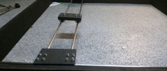
2.3 Started and dismantled the table. The conception is made using 2 crackers and the upper hole for the eye bolt. A clasp was used as insurance.
The conception diagram is taken from the manual. To secure and support the direction of the table, M12 studs were screwed into the mounting holes.
2.3.1 The table is supported by bolts around its circumference. Next to the fastening bolt there is a pair of screws that regulate the position of the table relative to the frame (in the photo there is a “regulating screw”). For convenience, it is better to unscrew the lower bolts while the machine is turned on, turning it using CNC.
Modern tendencies
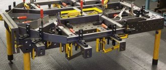
Machine additions are no longer new in today's market, but many craftsmen do not embrace the advancements in their workshop. It is worth taking into account market requirements and adopting the experience of foreign colleagues, especially when setting up your workplace.
Multifunctional tables are gaining popularity among craftsmen in many countries; thanks to the versatility of each component of the equipment, it is easy for people of different ages, heights and qualifications to work on them. CNC helps to supplement the arsenal with the automation of certain actions.
To fully work with a rotary table, you must have a large workshop area, proper ventilation, and high-quality lighting. You should not install multifunctional equipment in small rooms, this will complicate the work process and also reduce its efficiency.