What is affected by the number of turns in a transformer?
If we talk about the secondary windings of the transformer, then the value of the number of turns in them mainly affects the output voltage. Things are more complicated with the primary winding, since the voltage on it is set by the supply network. The parameters of the primary winding affect the no-load current, and, consequently, the efficiency. When changing the parameters of the primary winding, it will be necessary to recalculate all secondary windings.
And it is worth noting that it is better not to open the secondary winding of the CT.
Transformer power concept
An AC transformer does not produce electrical energy, but only converts it in magnitude. Therefore, its power completely depends on its load (current consumption) of the secondary circuit. If there are several consumers, the total load that can be connected simultaneously must be taken into account. For AC circuits, the active and reactive nature of consumption is taken into account.
We recommend reading: Varistor: principle of operation, main characteristics, designation on the diagram
Active
This component of the characteristic is defined as the average instantaneous value over a certain period of time. For sinusoidal alternating current circuits, the value of the oscillation period is used as a period of time:
T=1/f,
where f is frequency.
The active part depends on the nature of the load, that is, on the phase shift between current and voltage and is determined by the formula:
P=i∙U∙cosϕ,
where ϕ is the phase shift angle.
The active component of AC devices is expressed in Watts, as for DC circuits.
Reactive
A reactive load differs from an active load in that during one period of voltage fluctuations, electrical energy is not actually consumed, but is returned. As a result of the fact that devices with large capacitance or inductance (electric motors) are connected to the power supply device, a phase shift occurs between the current and voltage.
The reactive component of consumption is determined by the expression:
Q= i∙U∙sinϕ
The unit of measurement is var (volt-ampere reactive).
Full
The total power of the transformer takes into account all consumed and returned energy and is found from the expression:
S= i∙U
All components are related by the relationship:
S2=P2+Q2.
The unit of measurement is VA (volt-ampere).
Apparent power equals active power only in the case of a fully active load.
Nominal
The rated power of the transformer takes into account the possibility of operation of the structure, taking into account the connection of consumers of different types, that is, it is similar to the full one. At the same time, proper operation of the device is guaranteed for the entire declared service life under the specified operating conditions.
Rated power, like total power, takes into account the active and reactive nature of consumption, which can change during operation.
Expressed in volt-amperes.
Calculation method
The full calculation of the transformer is quite complex and takes into account the following parameters:
- supply voltage and frequency;
- number of secondary windings;
- current consumption of each secondary winding;
- type of core material;
- weight and size indicators.
At the household level, for the manufacture of devices powered by a standard 220V 50Hz network, the design can be significantly simplified.
The technique does not require special knowledge of complexity, and if you have experience, it takes little time.
The following data is required for the calculation:
- Number of exits.
- Voltage and current consumption of each winding.
The design of any transformer is based on the total power of all secondary loads:
Pс=I1∙U1+ I2∙U2+… In∙Un
To take into account losses, the concept of overall power has been introduced, for the calculation of which a simple formula is used:
P=1.25∙ Pс
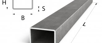
Knowing the power, you can determine the core cross-section:
S=√P
The resulting cross-sectional value will be expressed in square centimeters!
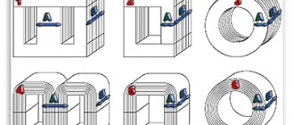
Further calculations depend on the type and material of the selected core. Magnetic cores are of the following types:
- armored;
- rod;
- O-shaped.
The methods for manufacturing magnetic cores also differ:
- typesetting - from individual plates;
- twisted, split or solid.
Armored or rod magnetic cores are usually split, while O-shaped ones are structurally made exclusively in one piece. In this respect, they are no different from continuous rod cores.
To determine the number of turns, use the following ratio, showing how many turns are needed per 1 volt of voltage:
W=K/S,
where K is a coefficient that depends on the material and type of core.
To simplify calculations, the following coefficient values are adopted:
- For stacked magnetic cores made of W- or U-shaped plates K=60.
- For split magnetic cores K=50.
- For O-shaped cores K=40.
As you can see, the shortest length of the winding wire, and therefore the best weight and size indicators, will be for O-shaped cores. In addition, designs with such cores have a small field of parasitic magnetic scattering and maximum efficiency. They are rarely used only because it is technically difficult to wind a winding around a closed core.
Knowing the parameter W, it is easy to determine the number of turns for each winding:
n=U∙W
To take into account the voltage drop on the primary winding, wound with a large amount of thin wire, the number of turns in it should be increased by 5%. This is especially true for small-sized, low-power structures.
You can reduce the no-load current by increasing the W value for each of the windings, but you should be aware that an excessive increase can lead to saturation of the magnetic circuit, which will lead to a sharp increase in the no-load current and a decrease in the output voltage.
At the final stage, the diameter of the conductors of each winding is determined. The calculation formula is as follows:
d=0.7√I
The diameter of the winding wire is determined for all windings without exception.
The resulting values are rounded to the nearest larger standard wire diameter.
Methods for determining efficiency
Transformer efficiency can be calculated using several methods. This value depends on the total power of the device, increasing with the increase in the specified indicator. The efficiency value ranges from 0.8 to 0.92 at power values from 10 to 300 kW.
Knowing the value of the maximum power, you can determine the efficiency value using special tables.
Direct measurement
The formula for calculating this indicator can be presented in several expressions:
ɳ = (Р2/Р1)х100% = (Р1 – ΔР)/Р1х100% = 1 – ΔР/Р1х100%,
- ɳ – efficiency value;
- P2 and P1 – respectively the value of useful and consumed network power;
- ΔР – the value of the total power losses.
From this formula it is clear that the value of the efficiency indicator cannot exceed one.
After a step-by-step transformation of the above formula, taking into account the use of the values of electric current, voltage and angle between the phases, the following relationship is obtained:
ɳ = U2хI2хcosφ2/ U2хI2хcosφ2 + Robm + Рс,
- U2 and I2 – respectively, the value of voltage and current in the secondary winding;
- Robm and Rs - the amount of losses in the windings and core.
The presented formula is contained in GOST, which describes the definition of this indicator.
Efficiency calculations
Determination by indirect method
For devices with high operating efficiency, with an efficiency value exceeding 0.96, accurate calculation is not always possible. Therefore, this value is determined using an indirect method, which involves assessing the power indicators in the primary coil, the secondary coil and the allowed losses.
Assessing the characteristics of the transformer, it should be noted the high efficiency of using this equipment, due to its design features.
Alternative method for dimensions
The approximate parameters of the transformer, based on the available core, can be determined in another way, and then conclusions can be drawn about the possibility of further use.
Knowing the cross-sectional area of the magnetic circuit in square centimeters, you can estimate the maximum power that this converter is capable of providing:
PG=S2
It should be borne in mind that this power is dimensional, and the real one will have a smaller value:
P=0.8 PG
Usually, provided that the calculated power matches the required one, the primary winding connected to the 220 V network can be left untouched, recalculating only the parameters at the outputs.
How to calculate the number of turns of the primary winding?
We enter the initial data obtained in the previous paragraphs into the calculator form and obtain the number of turns of the primary winding. By changing the size of the ring, the grade of ferrite and the generation frequency of the converter, you can change the number of turns of the primary winding.
It should be noted that this is a very, very simplified calculation of a pulse transformer.
But, the properties of our wonderful self-excited power supply are such that the converter itself adapts to the parameters of the transformer and the load size by changing the generation frequency. So, as the load increases and the transformer tries to enter saturation, the generation frequency increases and the operation returns to normal. Minor errors in our calculations are compensated in the same way. I tried to change the number of turns of the same transformer by more than one and a half times, which is reflected in the examples below, but I could not detect any significant changes in the operation of the power supply, except for a change in the generation frequency.
Using a Multimeter
Using a multimeter, you can find data for recalculating the windings of an existing transformer. To do this, you need to make an additional coil from any available wire. After connecting the device to the network, it is necessary to measure the voltage on the additional coil. Now you can easily calculate the required number of turns per volt and recalculate the transformer to meet the required requirements.
Calculation of a pulse transformer of a push-pull converter
The advantage of push-pull converters is their simplicity and the ability to increase power. In a properly designed push-pull converter, a constant current passes through the winding, so there is no strong core bias. This allows you to use a full magnetization reversal cycle and get maximum power. Since it is performed on a ferrite core, the calculation of the output voltage of the transformer is similar to a conventional toroidal one.
You can simplify the transformer calculation options by using special calculation calculators, which are offered by some online resources. One has only to enter the desired data, and the machine will provide the necessary parameters of the planned electromagnetic device.
Table of volts per turn
In order not to constantly carry out calculations, you can use the table, which shows the average data of the windings depending on the power:
| Power, P | Section in cm2, S | Number of vit. /B, W | Power, P | Section in cm2, S | Number of vit. /B, W |
| 1 | 1.4 | 32 | 50 | 9.0 | 5.0 |
| 2 | 2.1 | 21 | 60 | 9.8 | 4.6 |
| 5 | 3.6 | 13 | 70 | 10.3 | 4.3 |
| 10 | 4.6 | 9.8 | 80 | 11.0 | 4.1 |
| 15 | 5.5 | 8.4 | 90 | 11.7 | 3.9 |
| 20 | 6.2 | 7.3 | 100 | 12.3 | 3.7 |
| 25 | 6.6 | 6.7 | 120 | 13.4 | 3.4 |
| 30 | 7.3 | 6.2 | 150 | 15.0 | 3.0 |
| 40 | 8.3 | 5.4 | 200 | 17.3 | 2.6 |
How to measure wire diameter
If you have a micrometer lying around at home, you can use it to measure the diameter of the wire.
It is better to first heat the wire in a match flame and only then remove the weakened insulation with a scalpel. If this is not done, then part of the copper can be removed along with the insulation, which will reduce the accuracy of the measurement, especially for a thin wire.
If you don’t have a micrometer, you can use an ordinary ruler. You need to wind 100 turns of wire around the tip of a screwdriver or another suitable axis, compress the turns with your fingernail and attach the resulting set to a ruler. Dividing the result by 100, we get the diameter of the wire with insulation. You can find out the diameter of the copper wire from the table below.
Example.
I wound 100 turns of wire and got a set length of -39 mm.
39 / 100 = 0.39 mm
Using the table, I determine the diameter of the copper wire - 0.35 mm.
Winding Wire Data Table
| Diameter without insulation, mm | Copper cross section, mm² | Resistance 1m at 20ºС, Ohm | Permissible load at current density 2A/mm² | Diameter with insulation, mm | Weight 100m with insulation, g |
| 0,03 | 0,0007 | 24,704 | 0,0014 | 0,045 | 0,8 |
| 0,04 | 0,0013 | 13,92 | 0,0026 | 0,055 | 1,3 |
| 0,05 | 0,002 | 9,29 | 0,004 | 0,065 | 1,9 |
| 0,06 | 0,0028 | 6,44 | 0,0057 | 0,075 | 2,7 |
| 0,07 | 0,0039 | 4,73 | 0,0077 | 0,085 | 3,6 |
| 0,08 | 0,005 | 3,63 | 0,0101 | 0,095 | 4,7 |
| 0,09 | 0,0064 | 2,86 | 0,0127 | 0,105 | 5,9 |
| 0,1 | 0,0079 | 2,23 | 0,0157 | 0,12 | 7,3 |
| 0,11 | 0,0095 | 1,85 | 0,019 | 0,13 | 8,8 |
| 0,12 | 0,0113 | 1,55 | 0,0226 | 0,14 | 10,4 |
| 0,13 | 0,0133 | 1,32 | 0,0266 | 0,15 | 12,2 |
| 0,14 | 0,0154 | 1,14 | 0,0308 | 0,16 | 14,1 |
| 0,15 | 0,0177 | 0,99 | 0,0354 | 0,17 | 16,2 |
| 0,16 | 0,0201 | 0,873 | 0,0402 | 0,18 | 18,4 |
| 0,17 | 0,0227 | 0,773 | 0,0454 | 0,19 | 20,8 |
| 0,18 | 0,0255 | 0,688 | 0,051 | 0,2 | 23,3 |
| 0,19 | 0,0284 | 0,618 | 0,0568 | 0,21 | 25,9 |
| 0,2 | 0,0314 | 0,558 | 0,0628 | 0,225 | 28,7 |
| 0,21 | 0,0346 | 0,507 | 0,0692 | 0,235 | 31,6 |
| 0,23 | 0,0416 | 0,423 | 0,0832 | 0,255 | 37,8 |
| 0,25 | 0,0491 | 0,357 | 0,0982 | 0,275 | 44,6 |
| 0,27 | 0,0573 | 0,306 | 0,115 | 0,31 | 52,2 |
| 0,29 | 0,0661 | 0.2bb | 0,132 | 0,33 | 60,1 |
| 0,31 | 0,0755 | 0,233 | 0,151 | 0,35 | 68,9 |
| 0,33 | 0,0855 | 0,205 | 0,171 | 0,37 | 78 |
| 0,35 | 0,0962 | 0,182 | 0,192 | 0,39 | 87,6 |
| 0,38 | 0,1134 | 0,155 | 0,226 | 0,42 | 103 |
| 0,41 | 0,132 | 0,133 | 0,264 | 0,45 | 120 |
| 0,44 | 0,1521 | 0,115 | 0,304 | 0,49 | 138 |
| 0,47 | 0,1735 | 0,101 | 0,346 | 0,52 | 157 |
| 0,49 | 0,1885 | 0,0931 | 0,378 | 0,54 | 171 |
| 0,51 | 0,2043 | 0,0859 | 0,408 | 0,56 | 185 |
| 0,53 | 0,2206 | 0,0795 | 0,441 | 0,58 | 200 |
| 0,55 | 0,2376 | 0,0737 | 0,476 | 0,6 | 216 |
| 0,57 | 0,2552 | 0,0687 | 0,51 | 0,62 | 230 |
| 0,59 | 0,2734 | 0,0641 | 0,547 | 0,64 | 248 |
| 0,62 | 0,3019 | 0,058 | 0,604 | 0,67 | 273 |
| 0,64 | 0,3217 | 0,0545 | 0,644 | 0,69 | 291 |
| 0,67 | 0,3526 | 0,0497 | 0,705 | 0,72 | 319 |
| 0,69 | 0,3739 | 0,0469 | 0,748 | 0,74 | 338 |
| 0,72 | 0,4072 | 0,043 | 0,814 | 0,78 | 367 |
| 0,74 | 0,4301 | 0,0407 | 0,86 | 0,8 | 390 |
| 0,77 | 0,4657 | 0,0376 | 0,93 | 0,83 | 421 |
| 0,8 | 0,5027 | 0,0348 | 1,005 | 0,86 | 455 |
| 0,83 | 0,5411 | 0,0324 | 1,082 | 0,89 | 489 |
| 0.86 | 0,5809 | 0,0301 | 1,16 | 0,92 | 525 |
| 0,9 | 0,6362 | 0,0275 | 1,27 | 0,96 | 574 |
| 0,93 | 0,6793 | 0,0258 | 1,36 | 0,99 | 613 |
| 0,96 | 0,7238 | 0,0242 | 1,45 | 1,02 | 653 |
| 1 | 0,7854 | 0,0224 | 1,57 | 1,07 | 710 |
| 1,04 | 0,8495 | 0,0206 | 1,7 | 1,12 | 764 |
| 1,08 | 0,9161 | 0,0191 | 1,83 | 1,16 | 827 |
| 1,12 | 0,9852 | 0,0178 | 1,97 | 1,2 | 886 |
| 1,16 | 1,057 | 0,0166 | 2,114 | 1,24 | 953 |
| 1,2 | 1,131 | 0,0155 | 2,26 | 1,28 | 1020 |
| 1,25 | 1,227 | 0,0143 | 2,45 | 1,33 | 1110 |
| 1,3 | 1,327 | 0,0132 | 2,654 | 1,38 | 1190 |
| 1,35 | 1,431 | 0,0123 | 2,86 | 1,43 | 1290 |
| 1,4 | 1,539 | 0,0113 | 3,078 | 1,48 | 1390 |
| 1,45 | 1,651 | 0,0106 | 3,3 | 1,53 | 1490 |
| 1,5 | 1,767 | 0,0098 | 3,534 | 1,58 | 1590 |
| 1,56 | 1,911 | 0,0092 | 3,822 | 1,64 | 1720 |
| 1,62 | 2,061 | 0,0085 | 4,122 | 1,71 | 1850 |
| 1,68 | 2,217 | 0,0079 | 4,433 | 1,77 | 1990 |
| 1,74 | 2,378 | 0,0074 | 4,756 | 1,83 | 2140 |
| 1,81 | 2,573 | 0,0068 | 5,146 | 1,9 | 2310 |
| 1,88 | 2,777 | 0,0063 | 5,555 | 1,97 | 2490 |
| 1,95 | 2,987 | 0,0059 | 5,98 | 2,04 | 2680 |
| 2,02 | 3,205 | 0,0055 | 6,409 | 2,12 | 2890 |
| 2,1 | 3,464 | 0,0051 | 6,92 | 2,2 | 3110 |
| 2,26 | 4,012 | 0,0044 | 8,023 | 2,36 | 3620 |
| 2,44 | 4,676 | 0,0037 | 9,352 | 2,54 | 4220 |