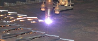
The most popular method of cutting metal nowadays is gas cutting. This is caused by a number of reasons. The main ones are:
- simplicity of the technological process. To carry out cutting, only two gases are needed: a gas heater for the material being processed (propane, acetylene, etc.);
- oxygen directly, which carries out the process of metal separation;
To perform this operation, you need a gas cutting machine - equipment for cutting metal with gas. This article will be devoted to getting to know this equipment.
By the way: other articles on our site are devoted to gas metal cutting technologies - you can easily find them if you use the “Site Search” service.
Features and varieties
Gas cutting of metal used to be widely popular in repair work. This cutting method was the main one.
The widespread use of this method is justified by a number of features:
- Expands the capabilities of cutting workpieces of large thickness;
- Does not require power from the mains;
- High performance;
- Ability to perform complex operations;
- Manual and automatic operating mode.
This method allows you to process carbon and alloy steels, titanium alloys, products made of brass, cast iron, lead, bronze, and aluminum.
Gas cutting can be classified into categories based on the nature of the cut:
- Dividing – characterized by performing a through cut, which divides the workpiece into the required number of parts;
- Surface – involves removing the surface layer of the workpiece, forming the necessary channels, splines and other structural areas;
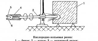
- Spear cutting involves burning the surface being processed to create openings or blind holes.
Thus, the method allows you to prepare a variety of metal parts and weld pipes of different diameters.
Technological stages
Metal gas cutting technology consists of the following steps:
- Heating the metal workpiece using a heater to a temperature of 1100°C;
- Introduction of oxygen flow into the treatment area;
- When oxygen comes into contact with a metal surface, ignition occurs;
- Under the influence of ignition, the workpiece begins to “burn”, forming the desired processing result.
The workpiece is heated under the influence of a mixture of combustible gas and technical oxygen.
Propane-butane composition, acetylene, natural, pyrolysis or coke oven gas are used as combustible gas. The most popular are acetylene and propane-butane composition.
During the ignition process, an oxide formation reaction occurs. They are blown out of the working area by a stream of oxygen. Metal oxidation occurs only in areas exposed to oxygen flow, which prevents reaction products from entering the metal. For the continuity of the cutting process, it is necessary to provide a jet of heating composition in front of the oxygen jet.
It should be taken into account that the melting temperature of the metal being processed must be greater than the ignition temperature in oxygen. Otherwise, the metal will not burn.
And also the melting index of the resulting oxides should be lower than the corresponding indicators for the metal. This is justified by the fact that otherwise the resulting products will not leave the working area, but will remain on the surface of the workpiece. When choosing a workpiece, you need to focus on the thermal conductivity of the metal. The lower it is, the easier ignition will occur.
Cutter - cutting device
Changing stages of the cutting process is ensured by special equipment. It implies an appropriate stable design for the stability and safety of the operations. One of the main components is a gas cutter. There are also nozzles for welding and melting used in conjunction with this equipment.
Cutting metal with a gas cutter requires precise dosage and combination of the gas mixture with oxygen. This device also provides a heating flame and the introduction of oxygen into the work area.
Well-known cutters are injection-type devices that work with steel up to 30 cm thick. This cutter connects the cutting and heating blocks. The heating unit includes valves responsible for supplying the gas mixture and oxygen. It also contains an injection cell, a mixing chamber, a supply tube, and an external mouthpiece.
The cutting block is formed by a pipe for outputting a cutting oxygen stream, a control valve, and an internal mouthpiece.
The gas mixture and oxygen move into the torch through different inlets. Oxygen moves into the injector and mouthpiece to create a cutting jet. After the injector, oxygen is supplied to the mixing chamber, where gas is also directed through its inlet opening.
After mixing, the composition ends up in the mouthpiece, which is responsible for the formation of a heating flame. Valves allow changing flows.
Cutters can be divided by area of use into:
- Manual – used for manual cutting;
- Machine - are used on cutting machines and machines.
There are also injection-free cutters and tools for feeding combustible mixtures of different compositions:
- Acetylene;
- Propane, butane and propane-butane;
- Universal;
- Natural gas cutters;
- Kerosene cutters - have an evaporation unit for producing gasoline, kerosene and gasoline-kerosene mixture vapors.
When starting to use any cutter, its serviceability is first checked. Then the device is purged with oxygen.
Equipment used
Cutting metal with gas involves the use of many basic and additional devices. In addition to the cutter, gas cutting equipment consists of:
- Reducer - used to reduce the pressure of the directed gas to the required value. There are two pressure gauges on it for measurements at the inlet and outlet sections.
- Pressure change tool.
- Gas and oxygen cylinders.
- Connecting hoses.
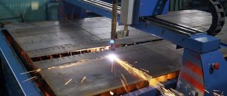
Equipment for cutting metal with gas: machines
In cases where for some reason it is difficult to move the workpiece being processed (it is large in size and, as a result, mass, complex cut shape, etc.), the kinematic diagram of the equipment changes. It is built in such a way as to move the assembly with the cutting tool (the heavy workpiece remains stationary). This type of equipment is called a gas cutting machine.
Gas cutting machines, like machines, are divided into two large classes:
- mobile . These are small mobile units that are moved using transport carts;
- stationary _ According to their design, they are divided into the following types: P - portal. They are located on support posts located directly above the workpiece. The number of cutters may vary, pcs: 1…12;
- P-K – portal-console. Installed on a console mounted on a stand. The suspension mechanism is located directly above the workpiece being processed. The number of cutters may vary, pcs: 1…4;
- Ш – hinged. The cutters are mounted on articulated frames. This type of equipment is intended for vertical cutting only. The number of cutters may vary, pcs: 1…3.
Based on the type of cutting technology, such machines are divided into types of processing:
- Kf – oxygen-flux cutting;
- K – oxygen cutting;
- Gl – gas laser cutting;
- PL – plasma arc cutting.
According to the trajectory of movement of the contour with the working tool, machines are distinguished:
- L – linear. They perform straight-line cutting;
- M – magnetic. Perform figure cutting on a steel copier;
- F – photocopying. Carry out figure cutting according to design drawings. The process is carried out through photoelectronic copying followed by microprocessor control;
- C – digital. Machine tools with numerical control (CNC). They are designed for figured cutting of blanks.
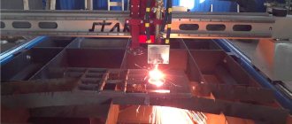
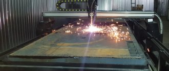
Currently, the following models and brands are in great demand:
- CNC gas cutting machine model “Start-2” brand “Teploventmash”;
- small-sized machine for gas-plasma cutting of metal with CNC model “Crystal 1.5x1” brand “PKF “Crystal”.
The cutting process on the Start-2 gas cutting machine. East. https://stanki-tvm.ru/produkciya/stanki-gazovoy-rezki-s-chpu.
Features and varieties
Gas cutting of metal used to be widely popular in repair work. This cutting method was the main one.
The widespread use of this method is justified by a number of features:
- Expands the capabilities of cutting workpieces of large thickness;
- Does not require power from the mains;
- High performance;
- Ability to perform complex operations;
- Manual and automatic operating mode.
This method allows you to process carbon and alloy steels, titanium alloys, products made of brass, cast iron, lead, bronze, and aluminum.
Gas cutting can be classified into categories based on the nature of the cut:
- Dividing – characterized by performing a through cut, which divides the workpiece into the required number of parts;
- Surface – involves removing the surface layer of the workpiece, forming the necessary channels, splines and other structural areas;
- Spear cutting involves burning the surface being processed to create openings or blind holes.
Thus, the method allows you to prepare a variety of metal parts and weld pipes of different diameters.
Technological stages
Metal gas cutting technology consists of the following steps:
- Heating the metal workpiece using a heater to a temperature of 1100°C;
- Introduction of oxygen flow into the treatment area;
- When oxygen comes into contact with a metal surface, ignition occurs;
- Under the influence of ignition, the workpiece begins to “burn”, forming the desired processing result.
The workpiece is heated under the influence of a mixture of combustible gas and technical oxygen.
Propane-butane composition, acetylene, natural, pyrolysis or coke oven gas are used as combustible gas. The most popular are acetylene and propane-butane composition.
During the ignition process, an oxide formation reaction occurs. They are blown out of the working area by a stream of oxygen. Metal oxidation occurs only in areas exposed to oxygen flow, which prevents reaction products from entering the metal. For the continuity of the cutting process, it is necessary to provide a jet of heating composition in front of the oxygen jet.
It should be taken into account that the melting temperature of the metal being processed must be greater than the ignition temperature in oxygen. Otherwise, the metal will not burn.
And also the melting index of the resulting oxides should be lower than the corresponding indicators for the metal. This is justified by the fact that otherwise the resulting products will not leave the working area, but will remain on the surface of the workpiece. When choosing a workpiece, you need to focus on the thermal conductivity of the metal. The lower it is, the easier ignition will occur.
Cutter - cutting device
Changing stages of the cutting process is ensured by special equipment. It implies an appropriate stable design for the stability and safety of the operations. One of the main components is a gas cutter. There are also nozzles for welding and melting used in conjunction with this equipment.
Cutting metal with a gas cutter requires precise dosage and combination of the gas mixture with oxygen. This device also provides a heating flame and the introduction of oxygen into the work area.
Well-known cutters are injection-type devices that work with steel up to 30 cm thick. This cutter connects the cutting and heating blocks. The heating unit includes valves responsible for supplying the gas mixture and oxygen. It also contains an injection cell, a mixing chamber, a supply tube, and an external mouthpiece.
The cutting block is formed by a pipe for outputting a cutting oxygen stream, a control valve, and an internal mouthpiece.
The gas mixture and oxygen move into the torch through different inlets. Oxygen moves into the injector and mouthpiece to create a cutting jet. After the injector, oxygen is supplied to the mixing chamber, where gas is also directed through its inlet opening.
After mixing, the composition ends up in the mouthpiece, which is responsible for the formation of a heating flame. Valves allow changing flows.
Cutters can be divided by area of use into:
- Manual – used for manual cutting;
- Machine - are used on cutting machines and machines.
There are also injection-free cutters and tools for feeding combustible mixtures of different compositions:
- Acetylene;
- Propane, butane and propane-butane;
- Universal;
- Natural gas cutters;
- Kerosene cutters - have an evaporation unit for producing gasoline, kerosene and gasoline-kerosene mixture vapors.
When starting to use any cutter, its serviceability is first checked. Then the device is purged with oxygen.
Equipment used
Cutting metal with gas involves the use of many basic and additional devices. In addition to the cutter, gas cutting equipment consists of:
- Reducer - used to reduce the pressure of the directed gas to the required value. There are two pressure gauges on it for measurements at the inlet and outlet sections.
- Pressure change tool.
- Gas and oxygen cylinders.
- Connecting hoses.
The reducer provides pressure regulation and automatic maintenance of the achieved value at a constant value. The gearbox can be formed by one or two chambers. If there are two chambers, the device rarely freezes, which affects the reliability and consistency of operations.
Gas cutting equipment
In the most general case, cutting metal with gas involves the following operations:
- cutting sheet steel at the procurement area;
- dismantling of metal structural elements at the assembly site;
- manual cutting of parts and assembled units;
- recycling of outdated structures and mechanisms and other types of work that do not require special precision.
The equipment for the above gas cutting of metal (hereinafter referred to as gas cutting) includes:
- gas-burner . It is equipped with a head located at an angle of 90° or 60° to the axis of the tool. The latter has several nozzles through which oxygen and heating gas escape;
- gas cylinders;
- pressure regulator;
- gas hoses (sleeves).
Acetylene generators
An acetylene generator is a device that creates acetylene by mixing calcium carbide with water.
Acetylene generator. East. https://weldering.com/acetilenovyy-generator
The process of mixing and chemical interaction occurs in stationary or mobile gas welding stations. They subsequently serve as sources of acetylene, a flammable gas for gas welding.
In accordance with GOST 30829-2002 “Mobile acetylene generators. General technical conditions" (hereinafter referred to as GTU), acetylene generators consist of the following main components:
- gasifier . This unit is designed to produce acetylene from water and calcium carbide;
- gas collector It performs two tasks: storing all generated gas;
- compensation of unevenness between gas formation and gas consumption of acetylene;
- localization of an oxygen-acetylene or air-acetylene mixture flame;
In addition, generators can be equipped with other functional elements:
- filters;
- pressure regulators, etc.
In accordance with the General Specifications, acetylene generators are classified according to the following parameters:
- according to the method of interaction of calcium carbide with water: VK – water on carbide;
- KB – carbide in water;
- K – contact, with process options: BB – water displacement;
- PC - immersion of carbide in water.
- N – low pressure. Parameter value (hereinafter referred to as PV), MPa: ≤ 0.02;
Additional technical requirements:
- generator productivity should not exceed, cubic meters/hour: 3;
- weight of unloaded generator, kg: ≤ 20.
When choosing equipment for gas cutting, you should carefully compare its capabilities with the tasks you face.
Gas welding kits and stations
Gas welding stations in everyday use have the following names:
- gas welding kits;
- gas welder's tool, etc.
Gas welding stations, depending on their size and power, are divided into mobile (transportable or portable) and stationary (in large industries). The mobile set is a special metal structure: a transport trolley or a portable box.
Gas welding station “PGSP-10/12”
The gas welding post (hereinafter referred to as ASG) is intended for transporting gas welding equipment and tools to the place of work and welding. The PGS is equipped with the following devices:
- cylinders . They are filled with oxygen and flammable gas (acetylene, propane, etc.);
- burners and cutters;
- combination and security keys;
- rubber hoses (gas hoses);
- clamps.
The ASG is equipped with a frame, which allows it to move easily and be used to perform a wide range of works:
- repair;
- emergency;
- installation.
The advantage of ASGs is that they allow welding work to be carried out far from sources of replenishment of consumables:
- during installation of pipelines;
- inside refrigeration systems;
- when carrying out plumbing work, etc.
The disadvantage of ASG is the need to refill cylinders with oxygen and flammable gas. This disadvantage becomes especially noticeable under conditions of intensive work, which requires increased gas consumption.
When choosing equipment you should:
- carefully decide: what you intend to do, what is the amount of work to be done;
- depending on the decision made, choose equipment.
When assessing the technical condition of the ASG, be sure to check the calibration and control documentation for the pressure gauge and valves.
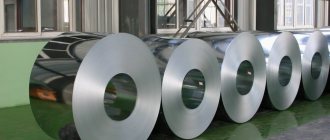
Gas cylinders
The set of ASG equipment for gas welding includes cylinders that are necessary for storing and transporting working gases. The latter are in a cylinder under pressure in one of the following states:
- compressed;
- liquefied
- dissolved.
Gas cylinders for welding have volumes, cubic meters. dm: 0.4…55. They are used in mobile (portable or transportable) and stationary ASGs. Cylinders with a capacity of 40 liters are more in demand.
Cylinders for ASG are manufactured in accordance with GOST 949 - 73 “Steel cylinders of small and medium volume for gases at Рр<=19.6 MPa (200 kgf/cm2). Technical specifications" (hereinafter referred to as TU), made of seamless steel pipes. They have the shape of a cylindrical vessel with a convex bottom and a narrow neck. Various devices are mounted on the neck:
- flanges;
- fittings;
- valves.
In the neck of the vessel there is a cone-shaped hole in which a thread is cut for a valve - a shut-off control device. The latter has a flywheel, the rotation of which opens or closes the gas supply valve.
A ring with an external thread for a safety cap designed to protect the valve is tightly installed on the neck of the cylinder. To ensure stability of the cylinder in a vertical position, a shoe with a square platform is placed on its lower part - a container with gas is placed on it.
Gas cylinders for welding or cutting metals vary in color.
Each gas has its own color cylinder
Each gas has its own color. The color coding of cylinders with the most commonly used gases is shown in Table No. 1. Table No. 1.
| Gas | Cylinder color | Lettering color | Stripe color |
| Oxygen | Blue | Black | – |
| Propane | Red | White | – |
| Acetylene | White | Red | – |
| Carbon dioxide | Black | Yellow | – |
| Nitrogen | Black | Yellow | Brown |
| Argon | Grey | Green | Green |
| Oil and Gas | Grey | Red | – |
The gas cylinder has its own individual passport, which indicates its technical parameters. In addition, all containers regularly undergo mandatory testing and inspection, the results of which must be indicated in this passport. It is attached to the body of the cylinder under the neck. When choosing cylinders, check their passports and the condition of the gas locking mechanism.
Cutters
This is the equipment for gas cutting that you cannot do without at all. Gas cutters on our website are discussed in detail in the article “Gas cutters”. Therefore, we will not repeat ourselves, and we recommend that you contact the specified address.
Burners
A gas welding torch is a device that allows proportional mixing of oxygen with flammable gas or flammable liquid vapor to produce a stable welding flame of the required power. Welding torches are mandatory participants in the gas welding process. They are intended for:
- heating the metal;
- welding of parts.
Therefore, they must satisfy a number of special requirements that are important when performing gas welding work:
- be able to create, shape, maintain and regulate a stable flame of the selected mode;
- have high mechanical strength;
- ensure safety during operation;
- have a small mass.
The burners are made of durable and high-quality material. As a rule, the welding torches themselves are made of brass, and the mouthpieces are made of copper. In some cases, light aluminum alloys are used for their manufacture. This significantly reduces the overall weight of the equipment.
Welding torches have different powers, which makes it possible to weld metal of different thicknesses. According to the flow pattern of combustible gas into the mixing chamber, gas burners are divided into two types:
- injection . They are used at low pressure of incoming flammable gas (less than 0.5 atmospheres);
- non-injector . They are used when the pressure of the flammable gas in the cylinder is higher than the specified value. In this case, gas can enter the burner without the help of an injector (on its own).
Schemes of acetylene torches. East. https://tm.msun.ru/tm/books/pats/lab3/lab3.html.
Explanation of the figure: a) injection burner; b) injection-free burner; 1 – burner barrel; 2 – nut; 3 – tip; 4 – mouthpiece; 5 – mixing chamber; 6 – injector; 7 – valve; 8 – connecting fitting.
Depending on functionality, gas burners are divided into the following groups:
- by method of application : manual;
- machine;
- single-flame;
- small Acetylene consumption, l/h: 25…400;
In accordance with GOST 1077-79 “Universal single-flame burners for oxy-acetylene welding, soldering and heating. Types, main parameters and sizes. General technical requirements", single-flame universal gas burners are divided into four types according to power output:
- G1 – micropower;
- G2 – low power;
- G3 – average power;
- G4 – high power.
The most common are burners of low and medium power (thickness of the metal being processed, mm: ≤ 0.2¬07 and ≤ 0.5¬30, respectively).
Oxygen and flammable gas must be mixed in a certain ratio. For example, the following ratio requirements apply to burners that are used with acetylene: Vк/Va = 0.8-1.5. The torch must maintain a constant mixture composition during welding.
When choosing, pay attention to the technical condition of the valves.
Trolleys for cylinders
The use of gas cylinders in metal processing is associated with certain inconveniences - they weigh quite a lot. This is especially true when moving them. The cart for cylinders, included in the equipment for gas cutting of metal, eliminates this drawback. In addition, the process becomes safer and more efficient. With its help, you can move cylinders over short distances without much effort. These carts for gas cylinders are safe because they have a reinforced axle for the wheels. In addition, more reliable and safe trolleys have a special design that allows gas cylinders to be moved at an angle of 45°. This design of the device has its advantages: it is more convenient and safe.
Please pay attention when purchasing, do not buy a cart that violates the safety regulations. According to the rules, cylinders are secured with a chain.
There are carts designed to transport one cylinder, two containers and other attributes necessary for welding (welding station). The cylinders are secured using a special galvanized chain. Carts for transporting cylinders with oxygen, propane and other flammable gases have the following load capacity, kg:
- for one container: 150;
- for two: 250.
Moreover, carts designed to transport two gas cylinders are equipped with a third wheel to reduce the load. It performs rotary-support functions. Its diameter is usually smaller than the two main ones:
- the main two wheels have a diameter, mm: 250 or 330;
- third (auxiliary) – mm: 160.
Let's look at examples of the most popular trolleys for gas cylinders among welders:
- series "GB 1" . Used to transport one cylinder (acetylene, oxygen, carbon dioxide, etc.). The trolley is easy to use, simple and, as a result, very reliable. The cylinder is fixed to the cart body with a galvanized chain. Equipped with a reinforced axle for mounting wheels. It is equipped with both pneumatic wheels and cast rubber.
- series "GB 2" . Used to transport two cylinders. In order to reduce loads and for ease of use, this trolley model has a third: a rotary support wheel, the diameter of which is 160 mm. The design of the trolley is reliable, simple, and easy to use. Fixing the cylinders to the cart body and equipping them with wheels is similar to the “GB-1”;
- series "PR" . Cart for transporting one propane cylinder. Fixing the cylinders to the cart body and equipping them with wheels is similar to the “GB-1”;
- “KP” series (oxygen + propane). Trolley for transporting two cylinders. It is equipped with an additional support wheel with a diameter of 160 mm. Fixing the cylinders to the cart body and equipping them with wheels is similar to the “GB-1”;
- series "KP-2 U" . Used to transport two cylinders and hoses (complete welding station). Fixing the cylinders to the cart body and equipping them with wheels is similar to the “GB-1”;
- series "GB-2B" . The welder's trolley is equipped with two powerful cast wheels with a diameter of 330 mm and has a design feature: it holds, without the help of a third wheel, 2 gas cylinders at an angle of 45°. The cylinders are fixed to the trolley using a galvanized chain;
- series "GBR" . The trolley is designed to transport 1 oxygen gas cylinder. Fixing the cylinder to the cart body and equipping it with wheels is similar to the “GB-1”.
When choosing a trolley, pay attention to the design of the wheel fastenings.
Valves
The classification of shut-off valves for cylinders depends on their contents. Therefore, valves are divided into the following types:
- fittings for liquefied gas cylinders;
- fittings for oxygen cylinders;
- fittings for propane-butane cylinders.
As an example, consider the design of an oxygen cylinder valve. Its diagram is shown in the figure.
Oxygen cylinder valve. East. https://experttrub.ru/zadvizhki/ventil-kislorodnyj-ustrojstvo.html.
Explanation of the figure: 1 – nut; 2 – spring; 3 – handwheel; 4, 7 – fiber gaskets; 5 – spindle; 6 – union nut; 8 – coupling; 9 – valve body; 10 – plug; 11 – valve body; 12 – seal.
Valve design and operating principle:
- valve body (hereinafter – designations in the valve figure: 9). This is a steel part that resembles a “tee” in shape. A conical thread is cut on its lower part (identical to the thread on the receiving hole of the cylinder). In the upper part of the body there is a cylindrical thread. It is intended for the union nut (6) holding the spindle (5). On the side outlet of the housing there is a cylindrical thread intended for the valve plug (10);
- locking element. This is a prefabricated unit (assembly), consisting of: a bypass valve (11), which regulates the flow movement through the body;
- stock It transmits torque from the flywheel (3) to the valve (11);
In addition, valves for high-pressure cylinders are equipped with gaskets and seals (4, 7, 12). These sealing structural elements are located between:
- body and union nut;
- nut and flywheel;
- valve and body.
The operation diagram of the valve on a gas cylinder for welding is very simple:
- A plug is screwed from the side fitting on the body. Instead, the welding hose reducer (sleeve) is screwed on;
- The valve flywheel is unscrewed with a smooth movement. He moves the valve, and the contents of the cylinder flow to the workplace;
- To shut off the gas flow from the cylinder, you need to do everything in reverse order.
When choosing a valve, you should pay special attention to the quality of the gaskets and the technical condition of the threads.
Gearboxes
Gas reducers are devices designed to reduce the pressure of a gas (gas mixture) at the outlet of a cylinder (gas pipeline, etc.) to the operating level. In addition, they automatically maintain this parameter constant, regardless of its changes in these cylinders or gas pipelines.
Gearboxes must comply with the GOST R 54791-2011 standard “Equipment for gas welding, cutting and related processes. Reducers and flow meters for gas pipelines and gas cylinders with gas pressure up to 300 bar (30 MPa).”
A diagram of a typical gearbox without a flow meter is shown in the figure.
Diagram of a typical gearbox without a flow meter. East. https://docs.cntd.ru/document/gost-r-54791-2011.
Explanation of the figure: 1 – setting screw; 2 – spring thrust washer; 3 – body; 4a – inlet fitting; 4b – inlet fitting nut; 5 – input filter; 6 – pressure gauge seal; 7 – high pressure gauge; 8 – pressure reducing valve cap; 9 – pressure reducing valve spring; 10 – spring thrust washer; 11 – reducing valve; 12 – safety valve cap; 13 – safety valve spring; 14 – safety valve seat; 15 – low pressure gauge; 16 – reducing valve seat; 17 – transfer rod; 18 – transfer disk; 19 – membrane; 20 – output connection; 21 – union nut; 22 – fitting for the hose; 23 – membrane seal; 24 – reducing spring; 25 – gearbox cover; 26 – thrust washer of the reducing spring; 27 – outlet valve.
Gas reducers: classification
- according to the principle of organizing the regulatory process : direct action. Gas through the fitting, entering the high-pressure chamber and acting on the valve, tends to open it;
- reverse action. The gas tends to close the valve. In practice, reverse-action gearboxes are most widely used, since they are more convenient and safe to use;
- B – balloon;
- A – acetylene;
- О – single-stage with spring pressure setting;
- at the inlet: 250 – for compressed gases;
- by gas consumption. This parameter, depending on the type of gearbox and its purpose, can vary from several tens of liters per hour to several hundred cubic meters per hour;
- According to the principle of operation, gearboxes are divided into: direct action. Gradually and simultaneously, both pressures decrease: working and in the cylinder;
- single-chamber. Used in cases of low pressure constant requirements;
Table No. 2.
| Type of gas | Code designation |
| Acetylene | A |
| Oxygen | ABOUT |
| Hydrogen | N |
| Compressed air | D or Air (air) |
| LNG (including propane, butane and propylene) | R |
| MAF | Y |
| Natural gas | M |
| CO2, nitrogen, inert gas | N |
The most common types of gearboxes are:
- oxygen. It has an unusually wide application: in industrial enterprises for gas welding, cutting, soldering, etc.;
- when performing welding in extreme conditions (underwater, in space) and many other types of work;
- with a constantly specified operating pressure, which is set at the manufacturer;
In addition to what is described above, the reducer can also serve as a pressure relief valve.
Gas cutter for metal - which one to choose, how to use
Cutting metal with a gas cutter is the easiest and most convenient way to divide a solid metal surface into the necessary parts. But this type of activity will require special equipment, the choice of which we will talk about in this article. In addition to the fuel cylinder and the cutter itself, it is worth paying attention to additional tips on caring for spare parts and operating principles.
The main components of gas cutters are almost the same; they vary depending on the purpose of cutting. The device differs only in ejector gas devices, but you can familiarize yourself with it only by carefully studying the operating instructions:
- fuel supply system, there is injection and ejector;
- inlets and connecting pipes;
- component mixing chamber;
- control valves for supplying mixed elements;
- nozzle - a tip for supplying liquid and gas.
The work of a carver is not so difficult as it is dangerous. It requires careful adherence to safety precautions. First you need to connect a gas cylinder and pump up the pressure to the desired level. At this time, all components form a single mixture. A jet of gases under pressure burns through the metal and does not allow the product to oxidize.
What are the types of gas cutters?
An important criterion for choosing equipment is the type of fuel on which the unit will operate. Experts identify the following product groups:
- Propane. It is most popular among professionals and amateurs. Safe and has a high efficiency. Capable of cutting through metal thicknesses from 3 to 500 mm, and its weight is 900 g.
- Oxygen. Injection fuel supply. Powered by oxygen, which creates a flash of fire due to high pressure. Capable of cutting through metal surfaces up to 300 mm.
- Acetylenic. It has proven itself well in working with thick products. Adjustable fuel supply affects the acetylene supply rate. It is presented in the form of a portable device and competes with stationary analogues.
- Kerosene. It is used in narrow areas of industry - mining and coal. Can be used underground. Cuts carbon material no more than 200 mm thick.
- Petrol. Works on 80,92 and 95 gasoline. A variant of a hand tool that performs the functions of a kerosene cutter.
- Hydrogen. The mixture of hydrogen and oxygen has the highest operating temperature. And the higher the heat, the faster the cutting is. This type of cutter is easy to maintain: you just need to add water to the tank. Often used in jewelry making.
- Combined.
Gas cutting machines
Gas cutting machines are divided into two classes:
- stationary _ This is powerful, high-performance equipment, the workpieces for which are delivered by special vehicles;
- portable _ These are small mobile units (massive ones are installed on self-propelled carts), the movement of which is carried out using: a spring mechanism;
- gas turbine;
- electric motor.
To use such a machine, it must be installed directly on the workpiece being processed (pipe, sheet, etc.) and directed in the desired direction (along a flexible copier, guides, etc.).
Models of both classes consist of the following main components:
- carrier. This is the “skeleton” of the unit on which the actuators and auxiliary mechanisms are mounted. For stationary machines, the “skeleton” is mounted on a powerful base;
- cutter. Powerful machines with high labor productivity are equipped with several cutters;
- leading. This unit is a drive mechanism, it is the source of movement of the entire machine and the workpiece being processed;
- Remote Control. From here all processes occurring on a gas cutting machine are controlled and monitored. There are types of control: manual;
- using CNC.
Portable gas pipe cutting machine “CG2-11”. East. https://www.mossvarka.ru/catalog/mashiny_gazovoy_rezki/.
The following models are very popular:
- portable gas pipe cutting machine model “CG2-11” brand “ZAO NPO “Vector” (Belarus);
- thermal cutting machine model “Kometa” brand “SPICOM” Barnaul.
Purpose of gas cutters
In terms of configuration, gas cutting tools differ in the number of tubes, size, and ignition method.
- industrial metal cutting machines are used for constantly large volumes;
- portable cutters, which are small in size, are intended for home use;
- tourist products are able to work at different levels of inclination;
- products with piezo ignition are started by pressing a button.
There are two groups of metal cutters:
- Air-arc. They are used in production to work with non-ferrous and ferrous metals. They have a high efficiency rate, but require constant contact with the electrical network and the compressor. Consumables need to be constantly purchased. Not used at home.
- Three-pipe system. It differs from most cutters in that it has a third tube through which oxygen is supplied. It is considered the safest tool. Increased gas pressure is required.
Consumables for work
Tips or nozzles of cutters often fail, so you need to stock up on the required number of mouthpieces or regularly care for the parts. After each work process, it is necessary to clean the nozzle hole with a copper or aluminum knitting needle, and also monitor the level of gas pressure when working with different thicknesses of material.
Gas cutting machine: conclusions
Gas is an explosive substance. To avoid injuries and casualties, the requirements must be strictly observed and the “Safety Rules” must be followed. Therefore, persons at least 18 years of age are allowed to maintain and operate gas equipment. They must go through the following stages of preparation:
- undergo introductory safety training when working with gas;
- on-the-job training;
- training course on safe work practices.
Upon completion of training, they must pass an exam on the theory and practice of safe working practices, which must be confirmed by receiving the appropriate “Certificate”.
Only competent, experienced welders with relevant work experience should always be involved in the selection, testing and training of working on gas welding equipment.
Rules for using a metal cutter
First make sure that all tubes are connected correctly, lubricate the taps with glycerin and tighten tightly. Degrease the surface, otherwise an explosion will occur from the contact of fat and oxygen. Now proceed to the main cutting step:
- first open the tap with oxygen, then with flammable gas;
- ignite the resulting mixture;
- adjust the jet to the required size and speed;
- walk on the metal surface at the cut site to warm it up;
- open the oxygen valve, make an incision;
- first close the flammable gas supply, then close the oxygen pipe;
- cool the tip.
It is worth reminding about personal protective equipment. Gloves, a mask and natural work clothes must be worn by the master. Choose comfortable shoes.