Manual hydraulic pump
Quite often, both in private farming and in construction and industry, it is necessary to pump liquid from one place to another. This can be ordinary drinking and industrial water, fecal waste, and chemical reagents.
For all these tasks, it is advisable to use different types of pumps. A manual hydraulic pump is the most affordable device that does not require electrical or other networks, and performs its functions under the influence of the human hand.
You should understand the design features of a manual hydraulic pump, their characteristics, and operating principle.
We will also look at the main varieties of this type of pumping device, their cost and tell you how to choose the optimal model for a specific situation.
What is it, the purpose and principle of operation of the device
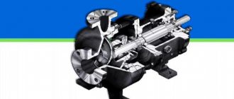
One class of machine - a hydraulic pump - is equipment for converting mechanical energy (rotation and torque of an electric drive motor; moving a piston when pressed and lifting a lever in a manual design) into hydraulic fluid energy (formation of pressure; feed or stroke of a working element, for example, hydraulic cylinder rod).
The classification and division of pumps into types does not affect the general principle of operation of the mechanisms - displacement of the working environment.
A working apparatus moves liquid from the suction cavity (input) to the discharge cavity (outlet) through insulated chambers.
The liquid leaving the mechanism body has increased pressure, causing it to move through the pipeline. Since the cavities are not directly connected, the devices are ideally adapted to work in high-pressure hydraulic systems. The liquid at the outlet transfers energy to the piston, moving it, or circulates in a closed circuit.
High-pressure hydraulic pumps are essential elements of a hydraulic drive and are therefore in demand everywhere. Main Applications:
- Mechanical engineering, oil refining, transport, agriculture, other manufacturing and processing industries.
- Equipment for mobile car washes, workshops, public utilities, construction sites.
- Systems for car cleaning, fire extinguishing, dust suppression, pipe cleaning, street washing.
- Pump – engineering, submersible.
Manual hydraulic pump: advantages and disadvantages
Pros and cons of equipment
Hydraulic hand pumps have more advantages than disadvantages.
The advantages include:
- Reliability of the design.
- Simple instructions for use.
- Light weight and dimensions.
- Autonomous work.
Let's take a closer look:
- The model does not require electrical networks. It can be used anywhere.
- The pump works perfectly without diesel fuel and pneumatics.
- To work you will need simple human strength.
If small volumes of work are envisaged, then manual hydraulic pumps are the best option. But there is a drawback: they are not suitable for large volumes due to low productivity.
Specifications and selection options
The main technical characteristics of the hydraulic pump are:
- Rotation speed, rpm.
- Working volume displaced per shaft revolution, cm3/rev.
- Operating pressure.
Remember! The basic units for measuring pressure have the following ratio: 1 atm=1.013 bar=0.101 MPa=1.03 kgf/cm2.
The selection of a pump for a specific hydraulic system is made taking into account the following criteria:
- Type of element that displaces liquid - piston, gear, plate.
- Requires a manual or electric hydraulic pump.
- Working pressure limits.
- What viscosity medium can the mechanism work with?
- Working volume.
- Frequency interval of operation.
- Ease of maintenance.
- Dimensions.
- Price.
Valve symbols – 3
3) HITACHI FOUR FLOW DIRECTION VALVE
Hitachi 4-Way Valve Symbols are similar to the 4-Way symbol, but with added connections and flow channels to show the bypass port.
Symbols for cylinder and motor spools are shown in the figure. Please remember that these symbols only show spool valves. The control valve block also shows the relief valves and connections to the body.
4) REducer VALVE
The pressure reducing valve symbol is shown in the figure and includes a normally closed valve with a built-in check valve.
The working process:
The pressure reducing valve is installed on the winch motor of the hydraulic crane.
(a) When the load is lowered, back pressure is created because there is a check valve.
(b) The pressure in the pressure line increases, the pilot line opens the valve to direct the flow of oil from the engine through the valve into the return line. This ensures protection against free fall of the load.
5) THROTTLE SYMBOLS
The basic throttle symbol means restriction.
6) SLOW RETURN VALVE
Adjustable throttle with built-in check valve.
The working process:
Gear
Rotary hydraulic machines of this type have found application in lubrication systems, road and agricultural special equipment, and mobile hydraulic structures. Their advantages include:
- simplicity of design;
- operation at frequencies up to 5000 rpm;
- light weight;
- compactness.
Notable disadvantages:
- working pressure up to 20 MPa;
- low efficiency;
- small resource;
- pulsation problems.
The working displacing elements of the structure are two gears. They differ in the type of engagement:
- External. From the inlet side, the gears rotate in different directions, capture the liquid in the cavities of the teeth and move it along the walls of the housing to the outlet of the pump. When the teeth engage, the working fluid is pushed out of the recesses towards the exit of the housing.
- Internal. The operating principle does not change. The fluid is transferred to the discharge area in the cavities between the gear teeth along the surface of the auxiliary crescent-shaped separator. Pressure pulsation and noise levels in such units are reduced.
Design
Let's look at how a hydraulic pump for a muscle-driven press is designed. A piston is installed in the cylindrical cavity of the pump housing, rigidly connected to the rod. The rod is pivotally connected to the drive lever. An intermediate valve is installed in the piston, connecting the piston and rod cavities of the pump.
The piston cavity is connected to the hydraulic tank through the inlet valve. In such pumps, the hydraulic tank is usually an integral part of their design. A suction filter is often installed in the tank in front of the inlet valve. The rod cavity is connected through the outlet valve to the outlet port of the pump. Special seals are installed in the pump housing cover, which also serves as a rod guide. A screw valve located in the bypass channel of the pump serves to return the working fluid to the hydraulic tank. A plug is provided in the housing for oil changes and maintenance.
Lamellar
In these hydraulic machines, the plates placed on the rotor do the main work. Special springs strengthen their pressure against the stationary body. Adjacent elements become limiters of the volumetric chamber, in which the working medium, when the rotor rotates, enters from the supply cavity to the discharge cavity. The presence of two or more suction areas and the same number of entry zones into the system is characteristic of double- or multiple-acting designs.
You need to know: only single-action mechanisms can be regulated.
Advantages of vane pumps:
- Reduced pulsation.
- Reduced operating noise.
- Reduced requirements for contamination of the transported medium.
- Adjustable working volume.
Minuses:
- The rotor bearings are heavily loaded.
- Low pressure.
- Difficulty in sealing the plates at the ends.
- Low maintainability.
G12 is a popular brand of single- and double-flow plate structures.
Valve symbols – 2
2) FLOW DISTRIBUTION VALVE
Check valve
A check valve opens to allow oil to flow in one direction and closes to prevent oil from flowing in the opposite direction.
Spool valve
The control spool valve symbol uses a complex closed system that has a separate rectangle for each position.
Four-hole valve
Typically a four-hole valve will have two compartments if the valve has two positions, or three compartments if the valve has a center position.
Lever control symbols
Lever control symbols represent a lever, pedal, mechanical controls or pilot line located on the edge of the compartment.
Miscellaneous
Tank
A rectangle with a long side horizontally is a symbol of a tank. The open top symbol indicates a vented tank. The closed top symbol indicates a sealed tank.
Battery
The accumulator is oval in shape and may have additional parts to indicate spring pressure or gas charge.
Oil cooler
The oil cooler is shown as a square, rotated 45° and has connections at the corners.
Filter/Strainer
Dotted line inside a rotated square
Symbols of hydraulic drive elements on hydraulic diagrams
Conventional graphic symbols serve to functionally represent hydraulic drive elements and consist of one or more basic and functional symbols. In accordance with the standards DIN ISO 1219-91, GOST 2.781-96 and 2.782-96, the following basic symbols are used:
- continuous line - main hydraulic line (suction, pressure, drain), electrical line;
- dotted line - control line, drainage, indicating an intermediate position;
- dash-dotted line - combining several components into a single block;
- double line - mechanical connection (shaft, rod, lever, rod);
- circle - pump or hydraulic motor, measuring device (pressure gauge, etc.), check valve, swivel joint, hinge, roller (with a point in the center);
- semicircle - rotary hydraulic motor;
- square (with a connection perpendicular to the sides) - hydraulic device, drive unit (except for the electric motor);
- square (with connection at the corners) - air conditioner of the working environment (filter, heat exchanger, lubricator);
- rectangle - hydraulic cylinder, hydraulic device, setting element;
- a rectangle open at the top - a tank;
- oval - battery, gas cylinder, supercharged tank.
Functional symbols include triangles (black for hydraulics, white for pneumatics), various arrows, lines, springs, arcs (for throttles), and the letter M for electric motors.
Hydraulic distributor symbols
In the designation of hydraulic valves, several squares are located nearby (in accordance with the number of positions, i.e. fixed positions of the spool relative to the body), and hydraulic lines are connected to one of the positions (initial): P - pressure, T - drain, A and B - for connection hydraulic motor. The number of hydraulic lines can be different: P, T, A and B - for four-line devices; P, T and A - for three-line; P, T1 (TA), T2 (TV), A and B - for five-line, etc.
Examples of symbols for hydraulic valves
In Fig. 1.6, a shows the symbol of a four-line three-position device (4/3 hydraulic valve) with electrical control from two pushing electromagnets (Y1 and Y2) and spring return to the original position 0, in which all lines are locked. When the Y1 electromagnet is turned on, the spool moves to the right, and you can determine the option of connecting the lines by mentally moving the square corresponding to position a to the place of the square at position 0. As you can see, lines P-B and A-T are connected. When the electromagnet Y2 is turned on in position b, a connection occurs between P-A and B-T. If it is necessary to show the connection of lines in intermediate positions at the moment of switching from one position to another, dotted squares are added between the main positions (Fig. 1.6, b). In hydraulic valves controlled, for example from a proportional electromagnet Y3 (Fig. 1.6, c), many different intermediate positions are possible, and two horizontal lines are added to the symbol. Conventional graphic symbols of the main elements of the hydraulic drive are given in table. 1.1.
Conventional graphic symbols of the main elements of the hydraulic drive
Example of a hydraulic circuit
Conventional graphic symbols of the main elements of the hydraulic drive
Letter position designations of the main elements of the hydraulic circuit:
- A - Device (general designation)
- AK - Hydraulic accumulator (pneumatic accumulator)
- AT - Heat exchanger
- B - Hydraulic tank
- VD - Moisture separator
- VN - Valve
- VT - Hydraulic displacer
- G - Pneumatic silencer
- D — Hydraulic motor (pneumatic motor) rotary
- DP - Flow Divider
- DR - Hydro throttle (pneumatic throttle)
- ZM - Hydraulic lock (pneumatic lock)
- K - Hydrovalve (pneumatic valve)
- KV - Hydraulic valve (pneumatic valve) time delay
- KD - Pressure hydraulic valve (pneumatic valve)
- KO - Hydrovalve (pneumatic valve) reverse
- KP - Hydraulic valve (pneumatic valve) safety
- KR - Hydrovalve (pneumatic valve) reducing
- KM - Compressor
- M - Hydraulic motor (pneumatic motor)
- MN - Pressure gauge
- MP - Hydrodynamic transmission
- MR - Oil sprayer
- MS - Oil Can
- MF - Hydrodynamic coupling
- N - Pump
- NA - Axial piston pump
- NM - Pump-motor
- NP – Vane pump
- HP - Radial piston pump
- PG - Pneumatic-hydraulic converter
- PR - Hydraulic converter
- P - Hydraulic distributor (pneumatic distributor)
- RD - Pressure switch
- RZ - Spool valve hydraulic device (pneumatic device)
- RK - Valve hydraulic device (pneumatic device)
- RP - Flow regulator
- PC - Receiver
- C - Separator
- SP - Flow adder
- T - Thermometer
- TR - Hydrodynamic transformer
- UV - Air bleeder device
- US - Hydraulic booster
- F - Filter
- C - Hydraulic cylinder (pneumatic cylinder)
Conventional and graphic symbols are used to depict various elements and devices on hydraulic diagrams - All sizes of conventional graphic symbols specified in the standards can be changed proportionally.
In addition, you can use other graphic symbols - Graphic symbols are made with lines of the same thickness as the communication lines.
To simplify the diagram drawing (reducing kinks and intersections of communication lines), conventional graphic symbols can be depicted rotated by an angle multiple of 90 or 45 degrees, as well as mirrored - Elements and devices of hydraulic, pneumatic and thermal circuits are shown in their original positions (check valve closed, springs in a state of compression).
On diagrams it is allowed to place various technical data, the nature of which is determined by the purpose of the diagram - They can be located near the graphic (on the right or top) or on the free field of the diagram (preferably above the main inscription).
Near the graphic designations of elements, their alphanumeric designations are indicated, and in the free field of tables, diagrams, text instructions - An alphanumeric designation consists of a letter designation (BO) and a serial number placed after the BO - BO schemes are determined by GOST 2.704-76 [50] - For designations, capital letters of the alphabet are used, which are initial or characteristic of the name of the element - Letters and numbers in positional designations on the diagram are made in a font of the same size - Sequence numbers must be assigned in accordance with the sequence of arrangement of elements or devices on the diagram from top to bottom in direction from left to right.
Technical data about the elements of the circuits must be written down in the list of elements - In this case, the connection of the list with the conventional graphic designations of the elements should be carried out through positional designations - For simple circuits, it is allowed to place all information about the elements near the conventional graphic designations on the shelves of leader lines - The list of elements is drawn up in in the form of a table and placed on the first sheet of the diagram above the main inscription, the distance between them must be at least 12 mm - The list can also be made in the form of an independent document in A4 format.
The main inscription indicates the name of the product and the name of the document - The following data is indicated in the columns of the list: in the column - the position designation of an element, device or designation of a functional group on the diagram; in column - the name of the 26th element in accordance with the document on the basis of which it was applied and the designation of this document - If it is necessary to indicate the technical data of the element, it is recommended to indicate them in the column.
The diagram may indicate the parameters of flows in communication lines: pressure, flow, temperature, etc., as well as parameters to be measured at control taps.
Types of oil pumps
All pumps for pumping oil can be divided into several categories according to purpose, functionality and technical design. The simplest and most inexpensive are manual models. They are most often found at car service stations, agricultural enterprises, and points of sale of bottled oils. Professional pumps for pumping oil are much less common. They can be immediately recognized by the presence of pressure gauges. Professional units for pumping oil include the following models :
- Diaphragmatic;
- Gate;
- Pneumatic.
Currently, manufacturers offer a wide range of oil pumps that can be used in the chemical, oil, household and other industries. In the economic sphere, such units are often used for pumping thick liquid soap. There are hybrid models that can be used to solve various problems. Purchasing such an electrically driven pump will be a good investment in the field. Where its highly specialized use is not intended. In other cases, it is better to choose a pump for pumping a specific type of oil or other liquid.