Wood carving is a fairly popular activity. There are many enterprises and small firms specializing in engraving and making all kinds of patterns on wood. Schoolchildren are also interested in this. You don’t need to look far for an example. What can we say, you open one of the many thematic forums on the Internet and see how fathers proudly tell that their sons are cutting out something with interest. Very often they ask advice from professionals, which machine or tool is better to choose ? Well, let's try to help.
There are more than enough types of tools and machines for figure cutting. There are both traditional and ultra-modern: manual, semi-automatic and automatic. There is not enough space to talk about everyone. Therefore, we will limit ourselves to the main types of electrical equipment. Firstly, it is universal. Secondly, it has a very wide range in terms of difficulty of mastering: from the simplest to the highly accurate. Thirdly, a wide price level can satisfy any requirements.
Cutting with a jigsaw
the most popular tool today . Professionals and home craftsmen value it, first of all, for its universalism. Having low weight and small dimensions, it copes well with shaped, transverse and longitudinal cutting of sheet wood. Can make curved and straight cuts, rectangular holes and round holes of various diameters.
There are household and professional jigsaws. Home models are low-power, but for domestic use their resources and functionality are quite sufficient. They can cut wooden pieces up to 70 mm thick. The total time of use is no more than 20 hours per month. They are produced mainly in Poland and China, but there is also a compromise Hungarian version - the inexpensive, functional BOSCH PST 700 E Compact .
The requirements for professional models are more serious. Therefore, these instruments are usually produced by brand companies in Japan, Sweden and Germany. They are highly productive and can withstand heavy loads, cutting wood up to 135 mm thick.
Saw blades or jigsaw files differ in size, teeth, color, tail shape and, of course, the material from which they are made. When working with wood, blades made of HCS (carbon steel) are used.
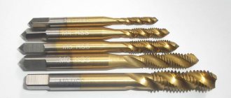
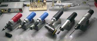
Cutting with an electric chisel
This power tool has become indispensable for every wood carver. Essentially, it combines an ordinary hand chisel and a mini-machine for processing wood. In a professional environment, it is also called a pneumatic or mechanized scraper .
An electric chisel works on the principle of a jackhammer. Nozzles are attached to the electric handle with a motor. They come in three types: straight, semicircular and angular.
The tool is used for processing soft and hard wood, as well as wood growths (burls, burls). An electric chisel allows you to remove a large amount of material without much physical effort, so it is excellent for roughing. At the same time, there are also very compact models. For example, a tool from Proxxon fits in your hand and can be used to work with small objects. But even tree trunks are processed with large models to create real sculptures.
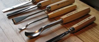
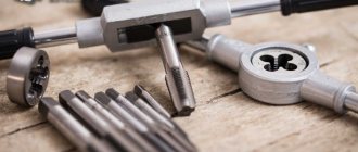
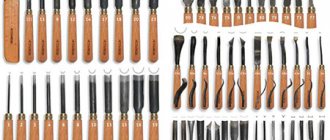
Main tool
A kitchen knife can easily cut out a whistle, a simple toy or a spoon. Many people start with a pocket knife for the purpose of carving a spoon. This is not woodworking or creativity - this is a memorable beginning. Tools for wood carving need special and, most importantly, sharp ones.
A beginner can start his practice only with this instrument. This is a blunt knife. If you want to cut out simple designs or give the desired shape to a wooden surface, this knife will help you do it perfectly. You don't need to specially learn to work with it. Once in your hand, this knife “will show you” how and what to do. There are only two conditions for the first tool:
- very sharp made of high quality steel;
- fits very comfortably in the hand.
There is no need to think about what tools are needed for wood carving and spend money on beautiful sets at the very beginning of practice - they will all be waiting in the wings. One sharp corner knife with a straight blade is enough.
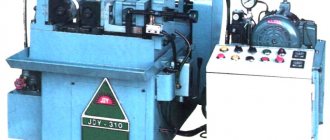
Cutting on a CNC milling and engraving machine
If the devices described above can be classified as both household and professional categories, then CNC milling machines definitely belong to the latter. This is high quality equipment with very wide functionality.
Despite the high cost of such equipment, it is in great demand among woodworking enterprises, furniture makers and advertising and production companies. The machines can process any wood (hard and soft wood), chipboard (chipboard), MDF (MDF), etc. They are used in the manufacture of furniture, signs, complex engraving and 3D carving.
One of the best models in the range of CNC milling and engraving machines is Beaver 1212 AT3 . Designed for high-quality milling and engraving of surfaces of parts and workpieces on a plane (2D software) and in 3-dimensional space (3D milling). It can be used to cut wood of any species, as well as composite materials (chipboard, fiberboard, MDF, plywood, etc.).
Types of wood carving machines
There is a wide range of wood carving machines that are designed to perform different types of work. They expand the range of operations performed:
- treat different surfaces at any angle;
- drill recesses, grooves and grooves;
- carry out milling of corners and bevels;
- do the carving.
Machines are divided depending on the design features of certain parts.
- According to the structure of the table. In this case, the difference between the models lies in the methods of moving the surface: Console machines have a work table that moves in a plane due to a rigid body part. These types of devices are quite popular. They are mainly used in small and medium-sized production.
- In non-console mechanisms, the table moves using a fixed frame in the longitudinal and transverse directions. Because of this, the device is difficult to move, but the workpieces are securely fixed.
- In large-scale production, continuous machines are used. These are non-console products with a rotating round table. They have two mechanisms - drum and carousel - and are designed for finishing and rough processing of workpieces.
- The simplest are devices with a simple spindle, which are located in the vertical direction. Such products are used for surface treatment and drilling recesses.
- Industrial types of machines are powerful products that process a large number of workpieces for several hours a day. The table in them moves with the help of flywheels, and the spindle is vertical.
Manual machines
Manual woodworking machines are divided into three main groups:
- Upper. They are distinguished by a fixed or movable design. The tool includes a powerful electric motor, which is connected by elements of a kinematic circuit to a chuck designed to fix the unit used.
- Craftsmen use an edge router to process the edges of wooden products. Additionally, the tool is equipped with additional attachments of various types.
- A plunge router is the most convenient. Its drive motor is installed on special guides, due to which it can move freely along with the working attachment during operation. Such models are equipped with a special spring that provides the volume of the working nozzle after the required area has been processed.
When choosing a manual machine, it is recommended to follow some recommendations that can help you avoid common mistakes:
- The speed control switch must be located in the housing to prevent special switching due to careless hand movement.
- There is no need to purchase an expensive instrument for home use. There is no need to overpay if the equipment will not be overloaded.
- The correct choice of machine depends on the clamps and clamps. The movement of all mechanisms should be smooth and easy.
- You should choose a device with a long power cord and a comfortable handle; this will allow you to process workpieces efficiently.
Milling and engraving machines
Such equipment is capable of performing work of any complexity in cutting and processing different types of materials.
Help: Blanks can have different sizes and hardness.
Milling and engraving machines can be used both in production and at home. The machines are classified as follows:
- Tabletop. Well suited for home use or small-scale production.
- CNC device. The device operates according to a specially launched program, where all the necessary parameters are specified.
- 3D devices. Their peculiarity is that they can process workpieces in two and three dimensions.
Reference: The equipment is also divided into longitudinal milling, cantilever milling, vertical milling and wide-universal. The latter is the most acceptable if you are seriously involved in the production of parts of different sizes.
When choosing a milling and engraving machine, you must consider the following parameters:
- The material to be worked with. The type of countertop depends on it.
- Height of the equipment along the Z axis.
- Table size. This value limits the size of the workpiece.
- Table rigidity. The more supports, the less vibration during operation.
- Engine power. It all depends on how many workpieces will have to be processed.
- Spindle. He is responsible for the speed of rotation of the cutter.
- Type of cooling system.
Laser machines
Wood cutting using a laser machine is a highly precise process, as the cut thickness is 0.2 mm. If you need to process small parts, then this option is perfect.
Important! Laser processing of wood is only possible if the thickness of the material is not higher than 20 mm. And sometimes this figure is even less, so this option is not suitable for processing thick workpieces.
The choice of laser equipment depends on its power:
- Desktop. Used at home or in a small workshop with compact workpieces. The power of such a device is up to 80 W.
- Professional. It is used in small businesses in the manufacture of designer jewelry and for engraving. Power is up to 195 W.
- Industrial. It is used on production lines with increased requirements for quality and precision of work. Power from 300 W.
Before you buy laser wood carving equipment, it is important to know how well it is made. Using low-quality devices can be dangerous, so it’s better not to skimp.
When choosing a laser device, consider the following:
- The power of the laser itself. The speed of wood processing depends on it. Usually they produce a whole line of similar equipment with different characteristics.
- The size of the table is also important, because when working with large sheets they must be on the work surface.
Help: For small jobs, it is better to buy small equipment that can be installed in any room.
CNC machines
Their versatility lies in the fact that they are suitable for cross planing and the creation of complex surfaces.
When choosing such equipment, you need to proceed from the extent to which it corresponds to its purpose. Highlight:
- CNC automatic machines with high speed, which cut and cut, process cardboard and wood.
- Devices that work with sheets.
- Engravers from 2D modeling to 4D.
- Narrow-profile devices that operate with a single material.
- Small CNC models.
Help: The line of equipment for professionals includes vertical and horizontal machining centers with program control.
There are several tips for wisely choosing such equipment:
- Before purchasing, consult with the seller regarding the functionality of the device and the range of tasks performed. The best option is to sign up for CNC machine demonstrations.
- When the required model is selected, you need to check the purchased device for components. The kit must include a machine program control unit, cords and disks with software. Usually the latter is installed by specialists who sell the equipment.
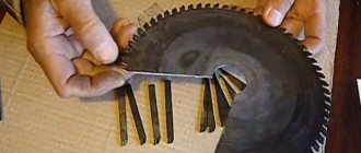
CNC plasma cutting
Plasma machines are the latest generation of CNC milling and engraving technology. Equipment of this type is intended for plasma arc cutting and milling of wood.
The machine looks like this: a supporting frame, including connecting elements and two drawers for water. Cutting is carried out with a milling spindle to a thickness of up to 16 mm. The maximum operating speed is 2.5 m per minute.
The units have a very stable design, allowing processing to be carried out with high precision. One of the best models of this type is the German machine High-Z PlasCUT-1350 . In addition to working with wood, he excels at cutting, milling and engraving metal, plastic and other materials.
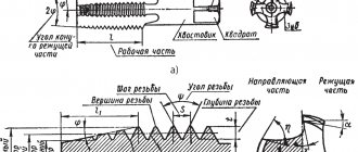
Contents (Updated) 1. Types of flat-relief carvings made on CNC machines. 2. Rules for constructing drawings. 3. Creating a vector model (drawing) in the CorelDRAW X7 program. Technology and overview of the necessary tools in CorelDRAW X7. 4. Cutters used. Description of technology. 5. Creating a control program for flat-relief threads in ArtCAMPro 9. 6. Possible defects when milling flat-relief threads on CNC machines and methods for its prevention. 7. Practical work. Creating a program for CNC (creating a vector model of a thread element in CorelDRAW X7, creating a control program in ArtCAMPro 9). Thread visualization. 1. Varieties of flat-relief carving performed on CNC machines. Flat-relief carving, performed on CNC machines, can be divided into several types. Carving in the body. This technology implies the following. The background of the thread drops slightly from the top point of the workpiece by 4-5 mm. Depending on the size of the pattern, the outer wall of the thread is removed with a 30 - 60 degree engraver (cutter). The center lines and all the various internal decorative elements of the design (petals, slots, etc.) are milled with a 90 - 120 degree engraver (cutter) See Fig. 1;2.
Slotted flat-relief carving.
Slotted flat-relief carving, in turn, can be made in several variations. The background is selected completely at right angles from the top point to the very bottom of the thread using a cylindrical end mill. See Fig. 3. The outer wall of the thread is formed halfway, or to a certain part, with a 30-60 degree engraver. Next, the rest of the background is removed (milled) with a cylindrical end mill. The carving is obtained with a so-called sole. See Figure 4.
The outer wall of the thread is formed entirely with a 30-60 degree engraver. See Figure 5.
Also, the slotted thread can remain in a specific frame and be part of the joinery structure. See Figure 6.
Or be an independent element and invest in an already prepared recess (selected background, ark). See Figure 7.
It should be noted that you can combine different types of flat-relief carving to obtain an interesting design solution. See Figure 8.
3. Rules for constructing drawings . When creating designs for flat-relief carving made on CNC machines, you should adhere to a number of technical, artistic and compositional nuances. Technical aspects consist in the conformity of the drawing with the possibility of milling it on CNC machines using the engraving method. For example, the thread backgrounds selected should not be too small for a cylindrical end mill. See Fig.9.
The center lines of the thread should not be too wide, because this will make them too deep with the centerline milling method. If the thread is slotted, then the thread elements should not be too thin or protruding, because chipping of these elements is possible. If the task is to quickly mill a thread, then the pattern should be drawn in the following way so that a minimum number of cutters are used when milling the backgrounds. This will save time on changing tools. Artistic and compositional nuances. When creating a design for flat-relief carving, it is necessary to pay attention to the aesthetic component: maintain composition, rhythm of the design, consistency, completeness in construction. All weaves in the pattern must alternate correctly and logically (top-bottom-top) See Fig. 10.
In the process of drawing, you need to avoid breaking the lines of the drawing (especially at intersections), maintain parallelism of the lines, and ensure that the middle line in the thread drawing is exactly in the center. It’s easier to draw drawings by hand on paper, then scan them and convert them into vector in CorelDRAW. Below you can see examples of drawings. See Figure 11.
2. Creating a vector model (drawing) in CorelDRAW X7. Technology and overview of the necessary tools in CorelDRAW X7 So, the drawings have been drawn and scanned, you can begin to create a vector model of the future carving. It should be noted that creating a vector drawing suitable for further use in ArtCAMPro 9 is a relatively complex and painstaking job. CorelDRAW X7 has a rich and comprehensive toolkit that will greatly simplify our work. Let's get acquainted with some basic tools with which we will create a vector drawing of the future carving. See Fig. 12.
The 3-Point Curve, Polyline, Bezier, Pen, and B-Spline tools are ideal for quickly converting a drawing into a vector. It is advisable to use this arsenal of tools with bindings enabled (for automatic merging of nodes). See Figure 14.
It should be noted that the “Curve through 3 points” tool is convenient if the quality of the traced (created) pattern is good. The “Contour” tool is very convenient and necessary for automatically constructing straight middle lines. This tool can also be used to build the shape of the entire thread. The Outline tool is indispensable when the drawing being translated is of very poor quality. See Fig. 15.
Use the Smart Fill tool to automatically create a closed new object from intersecting objects. Because the vector model of the future carving is built only on the basis of closed objects (this is a logical necessity for creating a control program based on engraving in ArtCAMPro 9), the “Smart Fill” tool greatly speeds up and simplifies the process of converting the drawing of the future carving into a vector. See Fig. 16.
The Blend tool is essential and very practical for creating an array of objects. Using this tool, it is possible to automatically distribute objects in one line or along a certain path (curve, circle) See Fig. 17.
The Transform tool is convenient for automatically copying and distributing objects either along one line or by rotating them around an axis point. See Fig. 18;19.
The Lens tool is effective for quickly cutting up a large collection of vectors and then creating a copy of them. See Fig. 20.
The Remove Virtual Segment tool allows you to quickly remove an unnecessary vector segment that is visually (virtually) formed by the intersection of other vectors. See Fig. 21.
The Knife tool is needed to cut an object. Moreover, when cutting one closed object, two independent closed objects are obtained. Convenient for trimming (editing) center lines in thread elements. See Fig. 22.
Technology for creating a vector thread pattern. When converting a drawing into a vector or creating a vector drawing from scratch, you need to adhere to certain simple rules (logic). Compliance with these rules will allow you to obtain a carving program in ArtCAMPro 9 using the engraving method. You need to create a vector in such a way that the entire drawing consists of closed independent elements (vectors), but when they are added, the illusion of the integrity of the drawing is created. See Fig. 23.
All elements of a vector drawing should not intersect or touch each other. The center lines should slightly (up to 1 mm) not reach the intersection. See Figure 24.
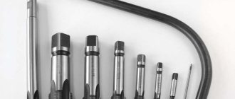
4. Cutters used. Description of technology.
It should be immediately noted that the quality of the tool that is used on CNC machines for milling flat-relief threads is very important. It is highly recommended not to use a low-quality tool from an unknown manufacturer. From my own experience, I can say that using a low-quality tool can lead to a number of problems. For example, with rapid wear of the cutting edge of the tool, non-compliance with the declared geometry of the tool, poor quality of surface treatment of the workpiece, excessive chipping during processing, excessive raising of pile during processing, etc. Types of cutters used for engraving threads. First of all, these are engravers (engraving cutters). The following engravers are used: 30? - 60 degrees, 90 and 120 degrees. See Fig. 25-26-27
Cylindrical end mills with a flat base with a diameter of 1 mm to 8 mm are also used. Engravers select the lateral inclined walls of the thread, the middle lines, petals, and undercuts at intersections. Cylindrical end mills are used to select backgrounds; these cutters are also used to trim threads along the contour if necessary (if the thread is overhead or slotted). See Fig. 28
Based on personal experience, when engraving flat-relief threads on CNC machines, I suggest using the following cutters. Dimar company, country of origin: Israel. And it is their new line of carbide replacement engravers. See Fig. 29.
It is advisable to have several holders for engraving plates 30-60-90 degrees. These engravers can mill the center lines, petals, and side walls of the thread. Also, for milling the sidewalls of carvings for hardwoods (maple, ash, oak, hornbeam), I would recommend an all-solid engraver with three cutting knives. See Fig. thirty
For sampling backgrounds and for cutting along contours, I recommend cylindrical end mills with a flat base from SGS Tool Company. 2-way for cutting and 3-way for sampling blind backgrounds. Country of origin: USA. 5. Creating a control program for flat-relief carving in ArtCAMPro 9. These recommendations will also be relevant for later versions of ArtCAM. After the drawing of the future thread is created in CorelDRAW X7. It must be exported to Adobe Illustrator 8.0 format. Next, in the ArtCAMPro 9 program, create a new model with the necessary parameters (height, width, resolution). See Fig. 31-32
, Import the previously saved vector drawing into ArtCAM. “File” - “Import” - “Import vectors” See Fig. 33.
Often the engraved design consists of a large number of elements to which different engraving methods will be applied. For the following reason, it is more advisable to arrange the drawing in layers. This will also help to quickly change certain engraving parameters (plunge feed, working feed, safety plane, etc.). For example, when milling a thread in a body (not through), you can create the following layers with the names: “Middle lines”, “Backgrounds”, “Petals” ", "Pruning". In order to create a new layer, you should have an attached “Vector” window in the right corner of the screen. See Fig. 34. (If this window is missing, press the F7 key on your keyboard)
, In order to create a new layer, you need to click the leaf icon (the first one in the left corner of the attached window) See Fig.35
Next, give the required name to the new layer; to do this, double-click the left mouse button on the layer name and enter the name. See Fig. 36.
Next, select the thread elements one by one (holding the Shift key) and move them to the desired layer according to the logic. Right-click on the selected objects, then select the “Move to layer” menu item, then select the desired layer from the drop-down list. See Fig. 37
,
Note! Also notice the light bulb icon next to the layer name. By clicking on this icon, you can enable or disable the display of vectors located on this layer. It is very convenient for group selection of the desired vectors using the lasso method. See Fig. 37(2)
Once the vectors have been laid out into layers, you can proceed directly to creating control programs. Let's look at the use of engraving tools in ArtCAMPro 9 using a practical example. You can download a vector drawing for completing a practical task for free here. See Fig. 38
Engraving backgrounds.
Turn off all layers, leaving only the “Backgrounds” layer. See Figure 39.
Next, we will diagnose the vectors for errors (checking for intersections, coincidence of vector points, the presence of loops). To do this, select all the vectors related to the backgrounds by throwing a lasso with the left mouse button, then in the top text menu select the “Vector” - “Vector Diagnostics” tab. See Fig. 40
Next, click the “Detect” button, uncheck “Save original”, then “Correct errors”. Errors that could not be corrected automatically are corrected manually. See Fig. 41
The next step is to select the “NC” tab from the bottom left - 2D NC, then the “Engraving” tool. See Fig. 42-43
Next, we create a list of tools that will be used when engraving this ornament (the “Add” button). In this particular case, this is a cylindrical end mill with a diameter of 1 mm (for milling backgrounds) and a 30-degree engraver for forming the walls of the thread. See Fig 44
Let's set up each of the cutters. First, the general parameters for all cutters are “Initial pass”, “Finishing pass”, “Accuracy”, check the boxes next to the parameters “Vectors on the surface”, “Cylindrical tool offset”. It is also necessary to set the “Safety height” parameter (individually, depending on how the workpiece is secured and how much the equipment protrudes) See Fig. 45
Next, we will set up a cylindrical end mill with a diameter of 1 mm. Let’s set up parameters such as “Step”, “Depth per pass”, “Working feed”, “Plunge feed”, “Rotation speed”, “Allowance”, “Machining strategy”. And we will also indicate the thickness of the material being processed. After setting all the parameters, do not forget to click the “Calculate” button UE See Fig. 46.
Next, let's set the engraver to 30 degrees. Let's set the following parameters as “Step”, “Depth per pass”, “Working feed”, “Plunge feed”, “Rotation speed”, “Allowance”, “Machining strategy”. Also, be sure to check the box next to the “Cutting corners” option. I would also like to pay attention to the next parameter as “Profile only”. Set this parameter if you do not want the engraver to clean up the background behind the cylindrical cutter. For numerical settings of the engraver, see Fig. 47.
To make sure that all cutters are configured correctly, make a visualization (simulation) of the UE. To do this, select “UE” in the top text menu - “Simulation of all UEs” See Fig. 48
The next step is to set up the cutter to cut the center lines. Let's turn off the display of the UE, and also turn off the layer with the backgrounds. In ArtCAMPro 9, select the 2D NC tool “Engraving along the center line” See Fig. 49
Next, we will select an engraving tool, in this case it is a 90 degree engraver (it should be noted that if you want to get deeper center lines, then select a 60 degree engraver), then we will configure the necessary parameters of the cutter and the “Center Line Engraving” tool. See Fig. 50.
Next, we calculate the maximum depth and width by clicking the “Middle Line” button. See Fig. 51
The next step is not to forget to calculate the UE. The final stage for this practical example is the formation of intersections of the so-called “cuts”. Hide the layers containing the backgrounds and midlines. Let's leave only the layer containing non-closed vectors that will form clippings. See Fig. 52
Next, select the 2D NC tool “Profile Processing”. Let's select the required cutter. In this case, it is a 30 degree engraver (the same as when engraving the background), the milling depth is 1.2 mm. The rest of the instrument settings are as in the figure. See Fig. 53
It should be noted that sometimes the vectors need to be rotated to form intersections so that the cutter passes on the side of the vector we need. In order to expand a vector, select it, then right mouse button, in the menu that appears, select the “Expand vector” item. See Fig. 54
Launch the final visualization of all UEs. If you did everything correctly, you should get something like in the picture. See Figure 55
Laser cutting
Today this is the fastest and most economical way to cut wood material. It is carried out with a gas CO2 laser, that is, without mechanical contact with the workpiece. This allows cutting along the most complex contours and with the smallest detail. It is impossible to achieve such precision with any other tools or machines. And the use of computer programs makes it possible to turn work into the most waste-free production possible.
Any wood material can be cut by laser. Even the veneer is only 0.6 mm thick. In general, technology opens up very great opportunities, allowing you to cut out original stories. The work of decorators and furniture makers cannot do without this installation.
True, the principle of operation requires high qualifications. Wood is a flammable material and therefore requires constant cooling. To do this, the machine blows into the cutting zone, which is controlled by the operator. In this way, maximum purity of processing is achieved (no carbon deposits are formed) and at the same time heat treatment of the part is carried out (it looks more contrasting and lasts longer).
Different types of wood are cut with a certain beam power and blowing force. And, if the workpiece is knotty, then this complicates the process even more. “Aerobatics” requires cutting plywood, because... glue layers burn hotter than wood. Yueming CMA series machine is perfect .
Waterjet cutting
The unique technology “TECHTRAN” , developed by Soviet scientists for the defense industry, and only relatively recently became available to the general public.
The principle of operation is to cut any sheet materials with an ultra-fine jet of water. Mixed with abrasive, it is fed under very high pressure to the cutting head, where it turns into the finest hair. The jet output speed allows you to cut even metal, not to mention wood.
Nowadays, a CNC system has been introduced into the technology, which makes it possible not only to cut, but to program the processing of material according to any sketch. Cutting accuracy – 0.1 mm. At a speed of up to 100 m/hour, the cut of wooden material is cold, the part does not heat up and does not deform. The cut edges are clean and do not need any finishing.
Vladislav Permin, specially for Equipnet.ru