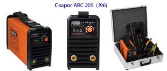
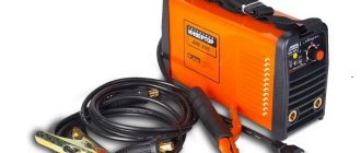
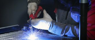
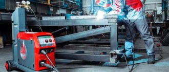
The semi-automatic welding machine is a very convenient device for working at home and in small workshops. You can work with it in any conditions, no special preparation of the workplace is required, it is compact almost like a regular inverter.
Unlike manual arc welding, it does not require a highly qualified welder to work with it. Correct setting of a semi-automatic welding machine allows even a low-skilled welder to perform high-quality work.
Depending on the type of material being welded and its thickness, it is necessary to correctly set the wire feed speed and shielding gas. Next, the welder needs to move the torch evenly along the seam, and a high-quality weld will be obtained. The whole difficulty lies in the correct selection of welding parameters for a specific material.
Equipment capabilities
To properly configure a semi-automatic welding machine, an understanding of the welding characteristics is required; it is also necessary to understand the features of the semi-automatic machine.
Semi-automatic welding machines allow you to work with almost any metals and their alloys. They can weld non-ferrous and ferrous metals, low-carbon and alloy steel, aluminum and coated materials, are capable of welding thin metals up to 0.5 mm thick, and can even weld galvanized steel without damaging the coating.
This is achieved due to the fact that flux, flux-cored wire or shielding gas, as well as welding wire can be supplied to the welding area, and the supply occurs automatically, everything else is done as in manual arc welding.
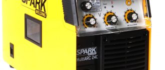
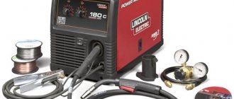
Semi-automatic welding machines are produced in different classes, but they all consist of:
- control unit;
- power supply;
- welding wire feed mechanism with reel;
- welding torch;
- power cables.
In addition, there must be a cylinder with a reducer and inert gas (carbon dioxide, argon or mixtures thereof), and a funnel for flux.
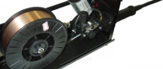
The wire feed mechanism consists of an electric motor, a gearbox and feed or pull rollers.
How to set up a semi-automatic welding machine
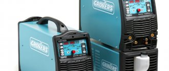
Welding technologies are becoming more and more accessible, so everyone can now buy a simple inverter, and more practical buyers choose semi-automatic welding machines. It would take a very long time to list the advantages of this technology, but in practice, owners are not always happy with their purchase. This is due to the fact that people simply do not know how to set up a semi-automatic welding machine. We have analyzed the main functions of budget and middle-class devices in order to use an example of their capabilities to explain how a semi-automatic device is adjusted.
Recommendations in the instructions
Before starting work, it is necessary to reliably ground the welding machine and only then begin setting up. The semi-automatic welding machine must be connected to a gas cylinder system with protective gas.
It is necessary to check the presence of welding wire in the spool, if you need to reload it and stretch it to the torch handle. The gas supply speed is of great importance in the welding process.
Therefore, it also needs to be installed. Gas equipment has gearboxes indicating gas consumption in liters. This is very convenient; you just need to set the required flow rate within 6-16 liters.
The operating instructions for the device provide recommendations on how to properly set up a semi-automatic welding machine, what current to use to weld a specific metal, and at what speed to feed the wire.
The instructions should contain special tables in which everything is described. If you set all the parameters in accordance with them, then everything should work out.
In practice there may be difficulties. The quality of semi-automatic welding is influenced by many parameters. If the supply network does not meet the standards, then the power source will produce voltage and current that is not what is needed, the parameters will be unstable.
The temperature of the medium, the thickness of the metal, its type, the condition of the surfaces being welded, the type of seam, the diameter of the wire, the volume of gas supply and many other factors affect the quality of semi-automatic welding.
Tables of recommended welding conditions are given for certain conditions, which cannot always be achieved. Therefore, when welding semi-automatically, many adjustments are made experimentally.
Of course, the recommended values are initially set, then the welding parameters are fine-tuned.
Tables of semi-automatic welding modes
As mentioned above, the experience and knowledge of experienced welders will allow them to set the correct welding modes without hesitation. But what about those who have only recently begun to master this specialty? There are special tables for setting modes for each type of welding. But you shouldn’t always use ready-made data; you need to experiment in practice and not be afraid to apply your accumulated experience and knowledge.
Table No. 1. Preferred settings for the formation of a butt weld in the lower spatial position, as well as for welding low-carbon and low-alloy steels in a shielding gas environment (carbon dioxide, a mixture of carbon dioxide with oxygen and carbon dioxide with argon) using reverse polarity current.
Table No. 2. Recommended semi-automatic welding modes for forming rotary butt joints using carbon dioxide, a mixture of carbon dioxide and argon; argon with carbon dioxide and oxygen, in relation to a current of reverse polarity.
Table No. 3. Preferred semi-automatic welding modes for forming an overlap weld using carbon dioxide or a mixture of carbon dioxide and argon with a reverse polarity current.
Table No. 4. Preferred parameters of the semi-automatic welding mode for carbon steels in a vertical spatial position with reverse polarity using carbon dioxide or a mixture of carbon dioxide and argon.
Table No. 5. Preferred semi-automatic welding modes for horizontal connections using reverse polarity with protective carbon dioxide.
Table No. 6. Recommended semi-automatic welding modes for forming ceiling seams with reverse polarity using carbon dioxide.
Table No. 7. Recommendations for setting semi-automatic welding parameters in a carbon dioxide environment when working with carbon steels.
In conclusion, I need to give one piece of advice. If you unconsciously copy the average parameters of equipment settings given in tables and reference technical literature, you may encounter some inaccuracies and even typos. It is important for a welder not only to blindly duplicate recommendations, but also to approach each specific task creatively, with the necessary scrupulousness and increased attention to detail. This will be a guarantee of high-quality work.
Setting current and wire feed speed
First of all, the strength of the welding current is set, which depends on the type of material being welded and the thickness of the workpieces. This can be found out from the instructions for the semi-automatic machine or found in the relevant literature.
Then the wire feed speed is set. It can be adjusted stepwise or smoothly. With stepwise adjustment, it is not always possible to select the optimal operating mode. If you have the opportunity to choose a device, buy a semi-automatic welding machine with continuously adjustable wire feed speed .
The control unit must have a forward/reverse wire feed mode switch. When all the settings have been made in accordance with the operating instructions for the semi-automatic machine, you need to try working on a draft sample with the same parameters. This must be done because the recommendations are average, and in each individual case the conditions are unique.
At a high wire feed speed, the electrode simply will not have time to melt, there will be large deposits or shifts on top, and at a low speed it will burn out without melting the metal being welded, the weld bead will sag, and depressions or breaks will appear.
Color coding
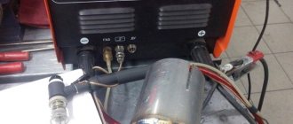
Essentially, a reducer is a pressure regulator for a welding mixture. It is a mandatory part of the equipment for semi-automatic welding machines that use the principle of welding in a protected gas environment. At least two gearboxes (each connected to its own cylinder) are used in a gas welding and cutting installation.
Of course, the best solution would be to choose only a reducer specifically designed for it for a cylinder with a certain gas. There is a strict color coding system:
- blue color with black inscription - oxygen;
- white with red text - acetylene;
- black with blue inscription - technical argon;
- black with white lettering - raw argon;
- black with yellow inscription - carbon dioxide (CO2).
Depending on whether you use gas welding, argon arc welding or carbon dioxide welding, choose the appropriate gearbox.
At the market or in a store, this can be easily done by color - the color of the welding gear matches the color of the cylinder for which it is intended. Blue is for oxygen, black is for argon (also suitable for carbon dioxide), and so on.
Adjusting parameters
Adjustment of current or voltage depends on the thickness of the workpieces. The thicker the product being welded, the greater the welding current. In simple semi-automatic welding devices, the current adjustment is combined with the wire feed speed.
In professional semi-automatic machines, the adjustments are separate. The correct setting can only be determined experimentally by making an experimental seam on a test piece. The roller should be of normal shape, the arc should be stable, without splashes.
Some semi-automatic models have inductance adjustment (arc settings). With low inductance, the arc temperature drops, the depth of metal penetration decreases, and the seam becomes convex.
This is used when welding thin metals and alloys that are sensitive to overheating. With high inductance, the melting temperature rises, the weld pool becomes more liquid and deeper. The seam bead becomes flat. Welding in this mode is used for thick workpieces.
The welding wire feed speed switch in models capable of working with different diameters requires additional adjustment taking into account the specific thickness of the wire.
Even after fully studying the manufacturer’s recommendations, it is not always possible to obtain the desired operating mode of the semi-automatic machine.
Having set the optimal settings for welding a workpiece today, it may turn out that the next day they will become suboptimal because the quality of the network has changed or the position of the product on the workbench has changed.
That is, setting the modes is a constant and individual process because it also depends on the work style of the welder himself.
Advanced semi-automatic machines. Share your work experience.
There is information about various variants of semi-automatic machines. Processor control (apparently wire drawing), soft start, arc stretching and something else. Maybe someone can share information about what kind of lotions these are, if they have real benefits. For example, inverter p/a are very expensive (min. 50 thousand), who has seen anything, heard anything about them, how do they work? For example MIX 180 TIG-MIG-MMA or ALUSTAR 200 cm.
The main feature of processor control is that the mode parameters can be set very precisely and you can enter a bunch of presets, this is very good. convenient and valuable in production, for example, welding only knows which operation to turn on which number, and the corresponding modes are set themselves. Those. This somehow additionally guarantees compliance with the technology. Well, from the “bells and whistles”, these are: 1) two or four stroke operation - two, this is if you press and cook while pressed, and stop when you release, and four, this is briefly pressed and released, the process begins, stop when you press and release again ; It seems like a small thing, but it’s nice. 2) point mode - press the button, cook for the specified time from a fraction of a second to about 3-4 seconds, then it stops itself, the next point is the next press. 3) pulsating mode - the duration/mode is set for the pulse and for the pause between the pulses and go, the seam turns out like nickels with overlap, beautiful. Moreover, during the pause, the feed may even stop altogether (MAG/MIG), and during the takeoff the arc burns very strongly. low current, the wire almost does not melt, such as illumination. 4) all sorts of internal bells and whistles to control the transfer of metal droplets, incl. receiving the so-called “jet” transfer. The essence of the trick is that at the right moments, the current/voltage changes very quickly in a cunning way (it will reduce it, then it will apply an impulse, all this in an interval of fractions to a few milliseconds), and this greatly improves the process. What these “necessary moments” are and how exactly all this changes - this is a great mystery, a terrible secret. All these nuances are not available to a welder, you just need to enable this feature, the machine itself is determined by the thickness of the wire and the metal being welded, depending on the specified mode, the spatial position of the ceiling/vertical/bottom, something else, for example, the composition of the gas (all this must be entered ). Particularly important and valuable for MIG.
All this in one form or another can be in a regular “classic” or in an inverter semi-automatic machine. Point 4 can be especially clearly and most fully implemented only in an inverter, because high speed control is required, which is fundamentally unattainable in conventional ones, therefore in conventional ones only in some truncated simplified form. By conventional we mean, of course, with three-phase power supply, because Only in them can the modes be clearly defined and stabilized from network fluctuations.
Conventional ones with single-phase power supply are always something extremely primitive and the cheapest, like all sorts of bimaxes, tritons, pythons, etc. rubbish. They cook much worse than three-phase ones; they fundamentally cannot stabilize the modes (well, maybe just the supply), i.e. This is an option for at least something where there is no three-phase input. For example, the output voltage there is set by switching the taps of the primary winding of the transformer, usually 4-5 positions from the lamp. The voltage, of course, changes, but it fluctuates along with all the network sags and fluctuations. Therefore, special bells and whistles in them do not make any sense.
Inverters with single-phase power supply are a completely different matter and somewhat different. These cook no worse than three-phase ones, they can stabilize and monitor everything, and therefore have a full load of bells and whistles. For example, Telvin’s Technomig 200, although it’s not sold in Russia yet, but an expensive toy will cost around 60 when it appears. I tried to find simpler inverters with single-phase power, but I didn’t come across anything, if anyone can tell me, respect. Well, single-phase inverters sometimes have a very valuable feature - an active power factor correction, or PFC. The essence of the feature is that inverters have a very poor power factor, usually 0.6-0.7, and pefek raises it to almost 1.0. This means that with the same welding current, the inverter with a pefek at the input will load the network by about 30% less, and in general can tolerate much larger fluctuations in the network, for example 170-270V lightly. This has no direct relation to the quality of welding, but for our realities it can be very useful. But the truth is the same Technomig 200, for example, without pefek, and I can’t even imagine its price if they add this too.
Common mistakes
An error in the settings of the semi-automatic welding machine is indicated by a distinct crackling sound. Loud clicks indicate that the solder feed rate is low. It is necessary to increase the feed speed until the cracking noise disappears.
Heavy spattering of metal is often observed. This is due to an insufficient amount of insulating gas in the weld pool area. It is necessary to increase the gas supply and adjust the semi-automatic gearbox.
There are lacks of penetration or burns in the seam. This is due to the arc voltage being too low or too high and can be adjusted by setting the voltage or inductance.
The uneven width of the weld bead is associated with the speed of movement of the torch and its position relative to the seam, that is, it is associated with the welder’s working technique.
If you follow the manufacturer's recommendations and understand the processes occurring in the weld pool and how to adjust them, you can perform quite complex types of welding work at home.
Pressure reducer UR 6-6
The domestic industry produces several types of pressure reducers - BUO-5MG, BUO-5-4, BUO-5 MINI, UR 5-3, etc., but the UR 6-6 brand reducer is considered the most compact and popular. Its features:
- Housing made of a special alloy that is resistant to various thermal and mechanical influences;
- The minimum value of the pressure unevenness coefficient is not higher than 0.3;
- Low pressure to activate the safety valve – 1.2 MPa;
- The presence of two pressure gauges, which facilitates the process of regulating carbon dioxide pressure.
- Increased throughput - up to 6 m 3 of gas per hour.
- Affordable price (up to 1100 rubles, versus, for example, 1700...1800 rubles for a carbon dioxide reducer model BUO-5-4).
The choice of a specific design of a carbon dioxide gearbox for a semi-automatic machine is not considered particularly critical, except for situations where metal has to be welded/cut at low temperatures.
What to choose
It is believed that for domestic welding conditions - short-term, occasional operations - any device that matches the thread of the cylinder is suitable.
Even a carbon dioxide reducer screwed onto an oxygen cylinder (if gas welding is used) or onto a cylinder for a welding mixture of 80% argon and 20% carbon dioxide can withstand an operation like welding a barbecue for a summer house. Another thing is that later this mechanism will have to be thrown away.
A typical example of such a gearbox designed to work with CO2 is the very well-known and popular among old-school welders UR 6-6.
It is compact, inexpensive, and thanks to the presence of two pressure gauges, it makes it quite convenient to determine the flow rate “by eye.” For household welding, high precision is not needed. One pressure gauge shows the residual pressure in the cylinder, and the second is aimed at demonstrating gas flow - liters per minute.
Oxygen and argon welding regulators are theoretically interchangeable. In this case, oxygen will work worse as the pressure in the cylinder drops to a critical point of about 1 atmosphere.
An example of an argon gearbox for welding is the domestically produced AR-40-2. There is also a truly universal pressure regulator - AR-40/U-30 (argon reducer/carbon dioxide). It will withstand both temperature changes and high pressure.
If there are no financial restrictions, and the volume of welding work is expected to be high, then you should prefer a device not with an additional pressure gauge, but with a rotameter.
The rotameter shows the flow rate of the gas mixture much more accurately, since it works on different principles - it takes measurements in real time. These devices are used by professionals.
For normal gas welding, the main equipment of the welding station is equipped with devices that provide a decrease and subsequent stabilization of the pressure of carbon dioxide coming from the gas cylinder. In our case, such a device is a carbon dioxide reducer. We'll talk about choosing a good gearbox and its correct configuration.
Design versions
Sizes and characteristics of devices must comply with the requirements of GOST 13861-89, ISO 2503-83 and GOST 12.2.052-81. Classification of carbon dioxide reducers can be made according to the following parameters:
- According to the number of working chambers. The predominant number of such devices are of the single-chamber type, however, to improve the stability of operation in conditions of low outside temperatures, double-chamber gearboxes are also produced. The working chambers in such devices are located sequentially.
- According to working conditions. There are ramp, network and balloon reducers. Ramp ones are intended for operation in multi-post areas, and network ones are powered by a stationary network laid from the carbon dioxide station of the enterprise. For the operation of individual posts, cylinder carbon dioxide reducers are designed, which are designed for lower specific gas consumption and a limited range of operating pressures.
- According to the principle of opening/closing the inlet valve, reducers for a carbon dioxide cylinder can be direct or reverse acting. The operating principle of the second type of gearbox is discussed above, and in direct-acting gearboxes all changes in flow and pressure occur in the reverse order. Such gearboxes are less convenient to use and therefore are used much less frequently.
Read also: Three-pin button with backlight connection diagram