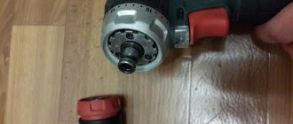
5 How to change brushes: work in a few minutes Unfortunately, the drill may not work due to obvious defects - for example, due to brushes inside the motor. This means that there is no way to do this without repairing the brushes; at the same time, this work is quite ordinary - you don’t even need to have any special knowledge or tools. For this purpose, we disassemble the device, remove the brush holders using it and replace parts that are broken. By the way, there are models whose body has the option of not disassembling - here you just need to remove special plugs through the installation window, then change the brushes.
You see, there are various breakdowns, probably where they will be subordinated to you, others will only be feasible for specialists in service centers. And in order to reduce the risk of such breakdowns, you need to take care of your tool, clean it after work, inspect the condition of the parts and brushes so that it’s time to replace them with new ones. But if you see that you can’t control it yourself, take the device to the workshop.
How to Connect a Screwdriver Button
A screwdriver is a mobile tool that makes it easier to work with fasteners and threaded connections.
Previously, you could only find cordless screwdrivers in the arsenal of experts, but when cheap household models became widely available, their popularity has increased sharply.
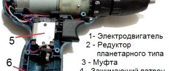
In contrast to expensive professional tools, economical analogues have the least resource, which is why they often fall into disrepair.
One of the weakest points of a household screwdriver is the start button and reverse switch. Practice shows that they break down in most cases.
You, our client is left with the fact that all additional parts are removed from the door, the soft start function stops working, and then a stronger pull on the “trigger” is required to start the electric motor.
Over time, the instrument completely stops responding to any manipulation. Often there is a problem of the opposite nature, when the motor begins to work spontaneously.
Sometimes, to eliminate the defect, it is enough to disassemble the tool and clean it, although more often a complete change of the screwdriver button . In both the first and second cases, you can remove the problem on your own. About many things in order.
The screwdriver button is the main control point, which performs several functions at once:
- Switching on/on the tool;
Switching direction of rotation;
Here, any of the control parts integrated into the button block are not actually able to work correctly. Not counting the rotation direction switch, which is often a very multifunctional unit.
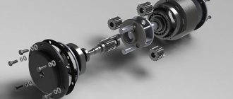
The case almost always consists of 3 conventional compartments, in which working units and mechanisms are located.
- At the bottom of the housing there is a control unit for turning on/off and adjusting the speed of the electric motor.
- The soft start “trigger” itself is located in the middle part (the deeper it is pressed in, the higher the rotation speed of the cartridge). When pressed, the button slides in a special block along the guides; a variable resistor is responsible for adjusting the speed.
- In the upper part there is a reverse button - a switch for the direction of rotation of the cartridge. The direction changes due to a change in the polarity of the voltage supplied to the switch.
This is roughly how the control units of screwdrivers of various brands are arranged for our client. To study the button structure of a certain tool model in more detail, we recommend studying the diagram of the screwdriver button (it is, of course, in the annotation).
To diagnose and repair a screwdriver, the following tools will be useful:
- Crosshead screwdriver;
- Screwdriver with a narrow flat slot.
During active use of any power tool, dirt inevitably accumulates inside its body.
Getting into the control unit, it prevents the real movement of the “trigger” and blocks it.
Stages of diagnostics:
- We disassemble the tool body. For this purpose, we disconnect the battery, unscrew it, and our client is left with the screws (they will be hidden behind decorative trims that will have to be removed).
- We check the serviceability of the electric motor. For this purpose, we disconnect two power wires from the control unit and connect them to the battery contacts (the engine should start working).
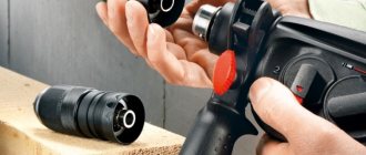
- We disassemble the screwdriver button. For this purpose, it is necessary to press out the plastic latches and separate the two parts of the button body.
- We visually inspect the condition of the button for dirt and damage.
- Next, you need to carefully assemble the screwdriver button, install it at its destination and test it.
If cleaning the control unit does not produce results, you need to replace the entire button unit.
- Disassemble the screwdriver (the process is described above);
- Install the new button at the destination of the old one;
- Connect the motor to the button terminals (maintaining polarity in our version is not necessary);
- Assemble the screwdriver, carefully placing the wires in the housing.
It is important to select a button for a specific screwdriver model, since despite all the external similarity and visual agreement, the part may not fit into the grooves. You, new buttons are sold complete with battery terminals and transistor.
Screwdriver speed controller
An electric screwdriver operates either from a 220 V network or from a rechargeable battery. Its power depends on the battery voltage. The screwdriver rotation speed starts at 15,000 rpm. In addition, a powered screwdriver has 2 rotation speeds: a slower one for screwing, a higher one for drilling. The speed control is located inside the power button. The rather miniature size of this tool assembly is achieved using microfilm technology. Its main part is a triac. The operating principle of the regulator is as follows:
- When the button is turned on, an alternating current having a sinusoidal phase is supplied to the control electrode of the triac.
- The triac opens and current begins to pass through the load.
The response time of the triac depends on the amplitude of the control voltage. The greater the amplitude, the earlier the triac is triggered. The amplitude value is set using a variable resistor connected to the start button. The button connection diagram differs in different models. It is possible to connect a capacitor to the speed controller.
Often, in the current economic conditions, the buyer cannot always afford a full-fledged expensive screwdriver from reputable companies. Cheaper models may not have this feature. But this is no reason to despair. You can assemble the speed controller yourself, which we will talk about below.
The screwdriver speed controller is assembled on the basis of a PWM controller and a key multi-channel field-effect transistor. The operation of this tool unit is controlled by a resistor. Its position depends on the pressure on the screwdriver start button.
The direction of rotation of the working body changes by changing the poles of the voltage that is supplied to the motor brushes. This is done instrumentally using changeover contacts actuated by a reverse lever.
It is possible to assemble such a regulator with your own hands. We will look at how to do this below.
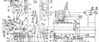
A diagram of the elements that make up the speed controller is shown in the figure below.
Scheme
In this case, a dual comparator microcircuit LM 393 is used. Here, the first comparator works as a sawtooth voltage generator, and the second one is PWM. The control signal for PWM is the voltage drop across the motor contacts. To put it simply, in the diagram the electric motor looks like active and inductive resistances connected in series with each other. When the load changes, the ratio of these resistances changes accordingly, the regulator controls this and changes the PWM filling, thereby stabilizing the speed.
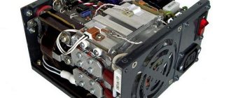
An electronic transformer should be used as the power source for PWM. It is a half-bridge voltage converter from 220 to 12 V, which is used to power halogen lighting lamps. Its dimensions are comparable to the size of a matchbox. The price fluctuates between 2–3 USD. e. It is necessary to add a rectifier to the output (these are four diodes, for example, KD 213), as well as a capacitor with a capacity of several thousand microfarads at 25 volts. All this will constitute a switching power supply with a constant output voltage.
We should also talk about making a printed circuit board for the regulator. To make it you need a sheet of photo paper and a laser printer. First you need to print the design on photo paper using a laser printer, then transfer it to the board blank using a heated iron. The board blank with the paper attached is placed in a container and placed under a stream of hot water. This is done so that the gelatin layer of the photo paper swells and it peels off from the board. The remaining pattern on the board is etched with ferric chloride.
Electronic screwdriver speed control
The rotation speed of the screwdriver attachment can be adjusted mechanically or automatically. Automatic speed control occurs using a processor. You can set the desired operating parameters using the speed selection toggle switch. It is located on top of the body. In many models, speed control is realized through the start button. The stronger the finger pressure on it, the higher the speed will be.
After reading this article, you received information on how to assemble a screwdriver speed controller with your own hands, became familiar with the design of the force regulator, and understood the function of electronic adjustment of the tool. We hope you found the article useful.
How to Connect a Screwdriver Button
A screwdriver is a mobile tool that makes it easier to work with fasteners and threaded connections.
Previously, you could only find cordless screwdrivers in the arsenal of experts, but when cheap household models became widely available, their popularity has increased sharply.
In contrast to expensive professional tools, economical analogues have the least resource, which is why they often fall into disrepair.
One of the weakest points of a household screwdriver is the start button and reverse switch. Practice shows that they break down in most cases.
You, our client is left with the fact that all additional parts are removed from the door, the soft start function stops working, and then a stronger pull on the “trigger” is required to start the electric motor.
Over time, the instrument completely stops responding to any manipulation. Often there is a problem of the opposite nature, when the motor begins to work spontaneously.
Sometimes, to eliminate the defect, it is enough to disassemble the tool and clean it, although more often a complete change of the screwdriver button . In both the first and second cases, you can remove the problem on your own. About many things in order.
The screwdriver button is the main control point, which performs several functions at once:
Switching direction of rotation;
Here, any of the control parts integrated into the button block are not actually able to work correctly. Not counting the rotation direction switch, which is often a very multifunctional unit.
The case almost always consists of 3 conventional compartments, in which working units and mechanisms are located.
- At the bottom of the housing there is a control unit for turning on/off and adjusting the speed of the electric motor.
- The soft start “trigger” itself is located in the middle part (the deeper it is pressed in, the higher the rotation speed of the cartridge). When pressed, the button slides in a special block along the guides; a variable resistor is responsible for adjusting the speed.
- In the upper part there is a reverse button - a switch for the direction of rotation of the cartridge. The direction changes due to a change in the polarity of the voltage supplied to the switch.
This is roughly how the control units of screwdrivers of various brands are arranged for our client. To study the button structure of a certain tool model in more detail, we recommend studying the diagram of the screwdriver button (it is, of course, in the annotation).
To diagnose and repair a screwdriver, the following tools will be useful:
- Crosshead screwdriver;
- Screwdriver with a narrow flat slot.
During active use of any power tool, dirt inevitably accumulates inside its body.
Getting into the control unit, it prevents the real movement of the “trigger” and blocks it.
Stages of diagnostics:
- We disassemble the tool body. For this purpose, we disconnect the battery, unscrew it, and our client is left with the screws (they will be hidden behind decorative trims that will have to be removed).
- We check the serviceability of the electric motor. For this purpose, we disconnect two power wires from the control unit and connect them to the battery contacts (the engine should start working).
- We disassemble the screwdriver button. For this purpose, it is necessary to press out the plastic latches and separate the two parts of the button body.
- We visually inspect the condition of the button for dirt and damage.
- Next, you need to carefully assemble the screwdriver button, install it at its destination and test it.
If cleaning the control unit does not produce results, you need to replace the entire button unit.
- Disassemble the screwdriver (the process is described above);
- Install the new button at the destination of the old one;
- Connect the motor to the button terminals (maintaining polarity in our version is not necessary);
- Assemble the screwdriver, carefully placing the wires in the housing.
It is important to select a button for a specific screwdriver model, since despite all the external similarity and visual agreement, the part may not fit into the grooves. You, new buttons are sold complete with battery terminals and transistor.
Repair of the electrical part of the tool - start button
Another malfunction of the Interskol Da-14.4 ER screwdriver may be a breakdown of the start button. It manifests itself in the absence of switching on of the tool, instability of operation, or spontaneous switching on. The cause may be metal dust formed, burnt contacts and a failed transistor.
To make sure that it is the button that is to blame for the failure of the screwdriver, you need to:
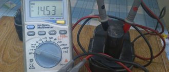
- Connect the battery and, after pressing the button, measure the voltage at its output. If it is missing, the button is faulty.
- Connect the engine and battery directly, bypassing the start button. For this purpose, remove the power source and remove the upper wire of the electric motor from the button. After this, two wires are connected at one end to the battery, and at the other to the motor housing and the wire going to the button. Turning on the screwdriver means that the trigger button is to blame.
Repair, as a rule, consists of replacing the old button with a new one. You can try to troubleshoot a used button. To do this, it is disassembled and, as necessary, the chips are removed, the contacts are cleaned, or the transistor is changed.
How to repair a device button? + (Video)
When everything is fine with the battery and charging proceeds without problems, but the tool refuses to activate, then check the serviceability of the device button.
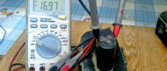
To do this, you will have to disassemble the device and at its terminals coming from the button, you should measure the voltage with a multimeter, which comes at the input of the button. The operation must be carried out with an active battery. If there is a signal, then the battery must be removed and its contacts short-circuited using clamps. On the multimeter you need to switch to Ohm mode. The screwdriver button is pressed all the way and measures the output voltage. If the resistance reading on the device tends to zero, then the button is working properly. This means that the problem should be looked for in the brushes or other electric motor modules. If a signal break is detected, it is recommended to repair the button, thereby returning the screwdriver to working order. Quite often, problems with buttons are associated with poor contact at the terminals. You can simply clean the contacts with sandpaper and the problem will be solved. The main thing is to do everything carefully during the process of disassembling and assembling the device, without losing parts.
Transistors STP60NF06. Screwdriver repair
At some point, during a cold start (after storage), the screwdriver began to ignore the force of pressing the button, immediately turning on the maximum speed.
After rummaging around on the net, I decided to first clean the insides of the button, since there was a possibility that the problem was the accumulated metal filings on the sliding contacts. I still don’t understand whether this is true, because during the assembly process I mixed up the polarity of the insert diode, which led to the transistor burning out. So I had to order a new one. To understand what I did wrong, I found a diagram of a button on the same chip as mine (GS069). It is slightly different; instead of a resistive track (potentiometer), I have tracks for resistive dividers on the board, but otherwise the circuit is the same. I noticed in time that both diodes in the diagram are shown with reversed polarity, otherwise it would have burned out another transistor. The mentioned insert diode does not have any markings and looks like a small iron washer with insulation around the perimeter; next time I disassemble the button, I will take a photo and show it here. Polarity is determined by a multimeter in dial mode.
I saw ready-made assemblies with a transistor and a button in a local store, they cost from 400 rubles. Perhaps the entire assembly should have been replaced at once, given the noticeable wear of the contacts, but I decided to save money; it was better to buy a normal tool for the money. Or, for a thousand and a half, you can rent just another Chinese screwdriver for the season with new gears, a motor, and a button. Replace it with a good battery and continue buzzing quietly.
At the time of delivery of the new transistor, I installed the less powerful IRFZ24N (17 A versus 60 A and 55 W versus the old 110 W); I couldn’t find anything else. The transistor is the same type, I was not afraid of compatibility. In all modes with the limit clutch turned on, the screwdriver does not develop enough power so that even such a relatively weak transistor is not enough. The mosfets parallel well; for reliability, you could assemble a sandwich from a couple of IRFZ24Ns.
I temporarily decided not to use the tool in difficult situations when it was necessary to remove restrictions, but my plans were disrupted when I urgently had to unscrew a hefty screw. At the maximum limit, the protection (ratchet) was constantly activated, the screw did not budge. I took a risk by setting the drill mode (without restrictions), and calmly did the job. But now the button again stopped responding to gradual pressure, immediately turning on the engine to maximum.
Having disassembled the screwdriver, I discovered that the replacement transistor had burned out and all its leads were short-circuited. I don’t know whether such transistors can burn out gradually. If so, then it is likely that the previous soft start problem could have been caused by the transistor. Perhaps installing a more powerful battery somehow affected the life of the transistor. New transistors were still on the way, so I inserted a second spare IRFZ24N for now. It was necessary to immediately put the pair in parallel, perhaps they would have pulled out a larger load, but it was not clear how to install both of them on a standard radiator. In general, I was lazy and paid the price.
Let's return to the order. I am 100% sure that the transistors ordered are not originals, because this is AliExpress, and there they only look for originals... but no one looks for them, everything is so obvious. On the other hand, I'm almost sure that the old transistor was fake too. The tool is Chinese, the likelihood of imported parts getting into it if there are cheap ones of our own is very unlikely.
There are no difficulties with installation. It makes sense to shorten the legs so they don't get in the way. The wires are soldered to the legs of the transistor with minimal overlap, so that later the soldering area can be covered with a plastic insulator. You can put thermal paste under the transistor. Initially it was not there, the surface under the transistor is uneven, but the transistor almost does not heat up during operation. The legs are tinned well, there were no problems with soldering, except that the legs are a bit soft and you need to handle them carefully; the legs of the old transistor are also soft.
I didn’t bother assembling a test bench or measuring the characteristics of the transistors, and I simply had nothing to drive them to the maximum parameters, except perhaps with a screwdriver itself, which is what I did. From past experience, I already knew that I still had to try harder to load the tool, so I immediately took a 6-mm screw under the PZ3 head and tried to screw it into a wooden block. The first 5 cm passed on the last tick of the fuse, after which the ratchet engaged. I set it to “drill” (unlimited mode) and drove the screw all the way.
And this is where things started to get interesting. White smoke with a noticeable odor began to emerge from under the ventilation grille. Burnt transistors smell different, most likely the motor windings are stinking. I quickly took the screwdriver apart and rummaged around everything inside. The button and the motor are the hottest, but the transistor is a little warm and intact. The smell is from the engine. This is not the first time that smoke has come out of this screwdriver; it also happened on the old battery, while it was fresh, under a heavy and long load, that is, this behavior of the tool seems to be normal :-), and the new transistor is not to blame.
The transistor has clearly coped with the maximum developed power of the instrument, and so far there are no complaints about it. I’ll add to this post later, the summer season is ahead, there will be something to check.
In stores you can find it under the line “stp60nf06”. You can also look for more powerful transistors, supply and demand may work in their favor. Lots less than 5 pieces seemed to me unnecessarily expensive (per piece), five pieces cost 130 rubles (26 rubles/piece). In the nearest local radio parts store I could buy them individually for 30-35 rubles per piece, but with transport or delivery it would be another +300 rubles, at a minimum. It is very likely that they are even original, but in practice it turned out that imitation is enough.
Update dated May 19, 2016
Coincidentally, during the first real use of the screwdriver after replacing the transistor, it suddenly rattled loudly and stopped turning the chuck. It turned out that the engine had unscrewed from the gearbox unit. If your screwdriver starts making rattling sounds, you may have the same problem - loosening of the mounting screws, which will eventually lead to their complete unscrewing. It’s easy to check - the engine and gearbox unit must be firmly connected, without play.
There is nothing to do with replacing the transistor, other than a coincidence in time