Description of the design of the 1N65 lathe
bed
The bed is the basic assembly unit on which all other assembly units and mechanisms of the machine are mounted.
On the top of the frame there are three prismatic guides, of which the front and rear are the base of the carriage, and the middle one is the base of the tailstock.
Inside the frame there are inclined hatches for removing chips and coolant in the direction opposite to the workplace.
Under the left head part of the frame there are niches, in one of which the main drive electric motor is mounted, and in the other - an electric cooling pump with a coolant reservoir. The trough for collecting coolant is made monolithic with the frame body.
On the right side of the frame, on the front wall, a bracket is mounted with supports for the lead screw and lead shaft built into it.
To prevent sagging of the lead screw and the lead shaft, the machine with RMC = 5000 mm has two suspensions. For machines models 1N65G and 1N65GF1, there is a recess in the frame in which a removable bridge is installed.
Headstock
The front headstock is installed on the left head part of the frame, fixed with pins and secured with bolts. Its body contains the following: an electromagnetic clutch for spindle braking, a spindle assembly, a link for increasing the pitch by 8 times, a mechanism for changing the direction of movement of the carriage or threading, a mechanism for adjusting spindle speeds, travel forks, handles and other parts, a lubrication system and an electrical cabinet.
The spindle is mounted on three rolling bearings, of which the front and rear are adjustable.
Tailstock
The rear headstock moves along the frame guides from the manual gearbox by rotating the roller.
A rotating spindle is built into the headstock quill, the front support bearings of which are adjusted using nuts.
The tailstock spindle has a slot for the legs of the tail cutting tool.
Caliper
The support of the cross design has longitudinal movement along with the carriage along the frame guides, and transverse movement along the carriage guides.
Both movements are carried out mechanically using a cross switch and manually by rotating the flywheel and carriage handle.
The cutting slide, carrying a four-position tool holder, moves manually and mechanically along the guides of the rotating part, which can be rotated around its axis at any angle.
The carriage of machines with a digital display device is equipped with a linear displacement transducer, which is connected to the transverse displacement screw using a bellows coupling.
The lateral movement can be counted using the dial and the DRO display.
Machine apron
The machine apron is of a closed type with a removable front cover. The movement of the caliper group is transmitted by the apron mechanism from the drive shaft or lead screw.
Due to the presence of four electromagnetic clutches in the apron, control of the mechanical movement of the caliper group is concentrated in one handle, and the direction of activation of the handle coincides with the direction of feed.
It is possible to enable rapid movement of the caliper in the direction of tilting the control handle.
Thanks to the overrunning clutch built into the apron, high speed can be activated when the feed is on. The rapid speed electric motor is installed on the apron.
A safety clutch mechanism is mounted in the apron, which prevents the machine from breaking due to overload.
Gearbox
Closed feed box with removable front cover.
The feed box mechanism allows you to get the first row of feeds and all the threads cut on the machine, without having to change the settings of the replacement gears.
To obtain the second row of feeds, replaceable wheels are installed: a = 42, b = c = l26.
Machine equipment
The machine includes a four-jaw non-self-centering chuck with a diameter of 1000 mm.
For processing non-rigid parts, the machine is equipped with two steady rests - movable and fixed.
The movable rest is mounted on the carriage and supports the part directly near the cutter. The breadcrumb coverage diameter is provided in the range from 70 to 250 mm.
The stationary steady rest is installed on the frame guides anywhere and secured with a bolt using a clamp.
It is equipped with crackers and rollers, which are installed depending on the processing conditions.
The diameter of coverage of the workpiece in the stationary steady rest is provided in the range from 70 to 380 mm.
MACHINE TOOLS ©™
| The largest diameter of the installed workpiece, mm | |
| - above the bed | 700 |
| - above the caliper | 350 |
| - above the recess in the bed | 900* |
| The largest diameter of the workpiece being processed, mm | |
| - above the bed | 630 |
| - above the caliper | 350 |
| Maximum length of workpiece processed, mm | 750; 1500; 2000; 3000; 4000; 5000; 8000; 10000 |
| Length of the recess in the frame from the end of the spindle flange, mm | 450* |
| Maximum weight of the installed workpiece, kg | 3500 |
| Height of the cutter installed in the tool holder, mm | 32 |
| Headstock spindle end size according to DIN | 11M |
| Internal cone in the spindle headstock (metric) | 115 |
| Number of spindle speed steps | 22 |
| Diameter of cylindrical hole in spindle, mm | 105 |
| Spindle speed limits, rpm | 10—1250 |
| Limits of working feeds, mm/rev | |
| - longitudinal | 0,033—5,6 |
| - transverse | 0,013—2,064 |
| - cutting slides | 0,010—1,76 |
| Limits of pitches of cut threads | |
| — metric, mm | 1— 224 |
| — inch, threads/inch | 28—0,25 |
| - modular, module | 0,25—56 |
| — pitch, pitch dia. | 112—0,5 |
| Accelerated movement of the caliper, mm/min | |
| - longitudinal | 5200 |
| - transverse | 2000 |
| Maximum cutting force, kN | 20 |
| Maximum torque on the spindle, kNm | 3 |
| Main drive power, kW | 15 |
| Overall dimensions (including electrical equipment), mm | |
| - length | 3000; 3740; 4230; 5240; 6240; 7240; 10300; 12420 |
| - width | 1780 |
| - height | 1550 |
| Weight, kg | 4200; 4840; 5100; 5750; 6900; 9000; 11800; 13200 |
www.stanok-machinetools.com
Modifications
Time and growing needs bring with it the need to make improvements. Our unit could not do without them. Its main modifications include the following models:
- 1M63F306, produced since 1973, was distinguished by the presence of CNC (this difference is also present in 1M63FZ and 1M63RFZ);
- 1M63F101, released in 1976, had a digital display device (DDU), which counted the lateral movement of the caliper;
- 1M63B, distinguished by its speed and increased power (this also applies to modifications 1M63BG and 1M63BF101);
- 1M63M with increased power, like 1M63MF101 and 16P30;
- 1M63N, released in 1992 and completing the series, was distinguished by normal accuracy (1M63NF1 and 1M63NF101, moreover, were supplemented by a DRO system that counted movements in a 3-dimensional coordinate system);
- 1M63N-1, which had normal accuracy and a shorter frame (1M63NF10M also had a digital display);
- 1M63NG, distinguished by a notch on the frame;
- 1M63NP, the advantage of which was increased accuracy.
Some of the listed machines could use a little more attention. For example, considering one of the latest modifications (1M63N), we can highlight several design features of the model:
- the letter “N” in the name indicates normal processing accuracy, which was ensured by three factors: temperature stability, vibration resistance and structural rigidity;
- impressive service life of the turning machine, ensured by two prismatic guides located on the bed, and other highly reliable components;
- accelerated thread processing due to the fact that reverse rotation of the spindle has a 30% higher frequency than direct rotation;
- gears, which are made of alloy steel;
- increased operational safety guaranteed by machine locking systems, as well as enclosing cutting zones;
- a more powerful engine compared to the original model;
- ability to process workpieces up to 10 m long and weighing up to 3.5 tons.
The 1M63 machine we reviewed has enough features that have ensured its popularity and recognition not only at home, but also abroad. A huge number of modifications were created on its basis, adding even more advantages to this machine. Despite the fact that in the new century a huge number of modern machines have already been created, superior in many ways to the half-century-old hard worker, he and his improved models continue to be in service, processing thousands of new parts every day.
To watch online, click on the video ⤵
#20 -Changing the oil in a lathe. What and how to pour? More details
How to properly LUBRICATE a 1k62 lathe. More details
The oil saga continues. Lathe 1k62 More details
What kind of oil to pour into the machine. More details
An oil fountain appeared. Headstock 1k62 More details
What oil to use to lubricate the machine lubrication system 1a616 Read more
Lathe 1K62 - Headstock, oil drain, cleaning. More details
A short review of the 1k62 lathe Read more
Lathe 1K62 - How to make wick lubricant Read more
How to mix oil and water. Changing the lathe oil Read more
About the 16k20 lubrication system Read more
How to cut threads on a 1k62 lathe Read more
Checking the machine upon purchase. №1 Read more
✅ Grooving brake discs / brake disk groove / الحز من الأقراص Read more
Homemade door handles made of epoxy resin. Epoxy Door Handles More details
Eternal oil level peephole Read more
LATHE .Changing the oil, cleaning the guitar/TV 4 oil changes,cleaning the guitar More details
1-3 Lathe Maintenance - Reboot with Improvements Read more
Electrical circuit diagram of the 1M63B machine
Electrical diagram of a screw-cutting lathe 1m63B
Main drive control
The electric motor is started by pressing one of the “start” buttons 1KU or 2KU (located on the carriage consoles and near the feed box) with the clutch turned off. At the same time, n.s. the contact of the limit switch VK is closed. The KSh starter receives power and connects the main motion electric motor to the network. Simultaneously with the KSh starter, time relays RV and 1RV receive power.
The spindle rotation is controlled using a friction clutch activated from the handle.
When the NC clutch is turned off. the VK contact remains closed, the time relay РВ, 1РВ and the brake clutch are turned on. At the same time, the signal dump 2LS lights up. When the main movement engine is idling, the time relay RV, set to a delay of 2.5-3 minutes, disconnects the magnetic starter coil and, accordingly, the engine from the network. At the same time, time relay 1РВ, set to hold for 25 seconds, will lose power and turn off the brake clutch.
When the clutch is turned on, NC. the VK contact breaks, turns off the time relay PB and ensures the operation of the machine. The engine is stopped by pressing one of the “stop” buttons 3KU or KU. At the same time, through n.z. Contact KSh turns on the RV relay and the 5EM brake clutch. The electric motor load is monitored using an ammeter.
Main drive motor current value depending on voltage:
380V = 29A
400V = 27A
415V = 26.5A
440V = 25A
500V = 22A
Feed drive control
Working feeds are carried out from the main drive motor, accelerated feeds from an accelerated feed motor type AOL2-21-4 (4Akh80A4UZ) 1.1 kW (1.475 hp) 1400 rpm at 50 Hz, 1690 rpm at 50 Hz.
There are four electromagnetic friction clutches in the machine apron, two of which are used to control the movement of the carriage in the longitudinal direction and two to control the movement of the support in the transverse direction.
The clutches are controlled by the handle of a cross switch mounted on the apron of the machine, which has 5 positions: one vertical neutral and 4 inclined, corresponding to the direction of movement of the support and carriage.
The activation of the rapid speed electric motor at any position of the switch handle is ensured by a push-start button built into the head of the cross switch handle.
To avoid simultaneous activation of the uterine nut and electromagnetic couplings, a blocking limit switch VKF is installed inside the apron, which breaks the power supply circuit of the couplings when the uterine nut is turned on.
To prevent breakdown of electromagnetic couplings and reduce sparking at the contact when the coil is disconnected, discharge resistances R1…R5 are provided.
On the apron of the machine there is a three-position operating mode switch, which turns on the clutches, respectively:
- turning work;
- taper turning (internal), closed contacts 53.57(1-2), 55-59(5-6)
- taper turning (external), closed contacts 53-59(3-9), 55-57(7-2)
Cooling drive
The cooling drive is carried out from an electric pump type PA-22, 0.12 kW (0.163 hp) 2800 rpm at 50 Hz, 3350 rpm at 60 Hz. Starting and stopping the electric motor is carried out by turning on a switch installed on the apron of the machine.
Description of the lubrication system of the 1M63.01 machine
The 1M63.01 machine uses an automatic centralized lubrication system for the spindle head and feed box.
The pump, driven from the main drive electric motor through a belt drive, sucks oil from the oil bath and delivers it through a strainer to the spindle bearings and oil distribution trays. About a minute after turning on the electric motor, the oil indicator disk on the spindle head begins to rotate. Its constant rotation indicates normal operation of the lubrication system.
During operation, it is necessary to monitor the rotation of the oil indicator disk on the spindle head of the 6K20 machine. When it stops, you must immediately turn off the machine and check the filter. Remove the filter mesh elements in the plastic frame. Rinse each element in kerosene until completely clean. Do not blow out the filter elements with compressed air, as this may damage the fine mesh. After cleaning, assemble and install the filter.
ATTENTION! Filters must be cleaned before and after each oil change. In a new machine, it is advisable to clean the strainer at least twice a week for the first two weeks, and then once a month.
Every day before starting work, you need to check the oil level in the tank using the indicator and, if necessary, add it through the hole in the filler filter. When changing the oil, the reservoir is drained through a plug. Before filling the tank with oil, it must be cleaned and rinsed with kerosene.
The apron mechanism is automatically lubricated by an individual plunger pump. Oil is poured into the housing through hole 5 (Fig. 3), closed with a plug, and drained through hole 6 (Fig. 3). The oil level is controlled by the oil indicator on the front side of the apron.
The frame guides are lubricated using a centralized lubrication system of the caliper apron (repeatedly, depending on the intensity of use).
The guides of the transverse carriage, the upper carriage, as well as their lead screws must be lubricated using an oil can.
The carriage guides and cross slides are lubricated at the beginning and middle of the shift until an oil film appears on the guides.
Every day at the end of the shift, you need to remove the cutting head from the 1M63.01 lathe, clean its working surfaces and lubricate the conical axis of the tool holder.
Replacement gears and the axis of the intermediate replacement gear 12 (Fig. 3) are lubricated manually with CIATIM-203 GOST 8773-73 grease.
The support bushings of the replacement gears are lubricated using an oil can.
The remaining points are lubricated manually using the oil can supplied with the machine.
ATTENTION! The first oil change should be made a month after putting the 1M63.01 machine into operation, the second - after three months, and then strictly following the instructions of the lubrication card.
Design
The basis of the 1M63N screw-cutting lathe is a cast iron bed with two or three pedestals for installation on the supporting surface (depending on the length of the machine). Two prismatic working guides located on the frame serve to move the caliper carriage, as well as adjust the position of the tailstock.
Kinematic diagram of a 1M63N screw-cutting lathe
Inside the frame body, under the working area, there are hatches for removing chips and draining coolant. The coolant and lubricant is reused many times, thanks to its return to the container through a filter system.
The outer (front and rear) cabinets of the frame are hollow. The main drive motor is located in the front (left), and the pump electric motor and a tank with cooling emulsion are located in the rear (right).
On the rear wall of the headstock there is a block of replaceable gears (guitar) for transmitting and adjusting rotation from the headstock to the feed shaft. Sets of replaceable gears allow you to rebuild the machine to cut threads of acceptable types.
Guitar screw-cutting lathe 1М63Н
Lubrication of the gears of the 1M63N screw-cutting lathe and its support bearings is carried out automatically using a mechanical oil pump driven from the main shaft of the headstock.
The high-quality alloy steel used for the manufacture of gears, heat-treated after the parts are manufactured, allows maintaining the accuracy of workpiece processing throughout the entire service life of the machine.
Feed box for screw-cutting lathe 1M63N
Gearbox of screw-cutting lathe 1М63Н
Installing and removing the machine chuck 1M63.01:
- When installing and removing the chuck, protect the guides and bed with wooden boards placed under the chuck. Hold the chuck while you loosen the 3 cam locks by rotating ¼ turn counterclockwise. Align the A marks with each other. Carefully remove the cartridge.
- Before starting installation, you should make sure that there are no nicks on the mating surfaces and thoroughly wipe them with a lint-free cloth. Install the chuck onto the front end of the spindle. Clamp the cam lock of the clamping eccentric by rotating clockwise. The clamping eccentric mark A (Fig. 5) must be located between the 2 marks B (Fig. 5). The accuracy of the chuck fit on the spindle is checked by an indicator using a control band located on the outer cylindrical surface of the chuck body. Radial runout should not exceed 0.02 mm. Fig.5 Installing and removing the machine chuck 1M63.01.
- The fixed steady rest serves primarily to support long workpieces and ensures their reliable processing without vibrations; it is mounted on the frame using a fastening strip. *
- Install the steady rest crackers so that there is no gap between them and the workpiece and they do not pinch it. During processing of the part, it is necessary to lubricate the crackers well.
- The movable steady rest is installed on the longitudinal slide of the support and thus repeats the movement of the turning cutter. It prevents elastic deformation of long and thin workpieces under the pressure of a turning tool. When machining a workpiece, it is necessary to install the crackers in the same way as on a stationary rest.
Location of lathe controls 163
Location of lathe controls 163
List of lathe controls 163
- Handle for setting metric or inch threads and feeds
- Handles for setting spindle speeds
- Handle for setting normal or increased thread pitch
- Handles for installing right-hand or left-hand threads
- Handles for setting spindle speeds
- Pull button for turning on or off the rack and pinion gear of the longitudinal movement of the caliper
- Handle for turning, fixing and securing the cutting head
- Handle for turning on or off the automatic movement of the upper caliper slide
- Button on the handle 10 to enable rapid movement of the caliper
- Handle for controlling fast and working movements of the caliper in all directions
- Handle for securing the tailstock quill
- Handwheel for moving the tailstock quill
- Handle for manual movement of the upper (incisor) slide of the caliper
- Handles for starting, stopping and reversing the spindle
- Handles for engaging the lead screw nut
- Push-button stations for starting and stopping the main drive
- Switch of electromagnetic apron couplings for normal work or taper turning
- Handles for manual lateral movement of the caliper
- Pull button for turning on or off the mechanical lateral movement of the upper caliper slide
- Handwheel for manual longitudinal movement of the caliper
- Push-button stations for starting and stopping the main drive
- 22 Handles for turning on, stopping and reversing the spindle
- Handle for turning on the lead screw or lead shaft
- Handle for setting the thread pitch feed value
- Handle for setting the thread pitch feed value
Machine lubrication 1M63.01.
Correct and regular lubrication of the 1M63.01 lathe is of great importance for its normal operation and durability. Therefore, you must strictly adhere to the recommendations below.
When preparing the machine for startup, it is necessary to wash the filter mesh in kerosene, then, in accordance with the “Lubrication Card” and the lubrication diagram (Fig. 3), fill the reservoirs with lubricant and lubricate the mechanisms indicated in the card.
Lubrication should be carried out with lubricants specified in the lubrication chart, or their substitutes given in the “List of recommended lubricants” (clause 6.3).
User manual
The equipment passport contains a complete list of rules for working with the 1m63 machine. Briefly we can mention:
- Personnel who do not have sufficient qualifications, who are not familiar with the documentation for the equipment, and who have not undergone safety training are not allowed to work;
- Before starting work, it is necessary to check the guards, replaceable gears, automatic switches, chip ejection blocking, and feed switches;
- do in the caliper must be securely fixed;
- when working with long workpieces, the use of steady rests is mandatory;
- immediately after start-up and for some time - do not switch the gearbox to the maximum spindle speed mode;
- the spindle rotation direction should only be switched when it is completely stopped;
- It is not allowed to switch the modes of the headstock wheels or feedbox operation while moving.
General safety rules must be followed. Overalls, except trousers, overalls with long sleeves and tightly buttoned cuffs, must include safety glasses and a beret. During work, do not touch moving parts, make sure that clothes are carefully tucked in, and it is not recommended to lean close to the work area.
All processing parameters must be configured before starting the machine according to the instructions for the equipment. The main drive must be activated after the cutter has been installed in the initial position. At the end of the work, you need to clean the surfaces of the machine from residual coolant, dirt, and remove chips.
Repair of equipment
Working on any equipment involves both scheduled and complex repairs. Measures to restore the functionality of individual mechanisms are required for the 1M63 model quite rarely. But a gradual loss of stability and loosening of individual structural components leads to a decrease in the accuracy of operations and a decrease in processing speed.
To carry out a comprehensive repair from the manufacturer, the customer must send the following documents together with the machine: a technical passport of the installation, special reports of previous technical inspections and a statement that reflects information about the assembly node modules.
Electrical circuit diagram of the 1M63D machine
Electrical diagram of a 1M63D screw-cutting lathe
Main drive control
The electric motor is started by pressing one of the “start” buttons 1KU or 2KU (located on the carriage consoles and near the feed box) with the clutch turned off. At the same time, n.s. the contact of the limit switch VK is closed. The KSh starter receives power and connects the main motion electric motor to the network. Simultaneously with the KSh starter, time relays RV and 1RV receive power.
The spindle rotation is controlled using a friction clutch activated from the handle.
When the NC clutch is turned off. the VK contact remains closed, the time relay РВ, 1РВ and the brake clutch are turned on. At the same time, the signal dump 2LS lights up. When the main movement engine is idling, the time relay RV, set to a delay of 2.5-3 minutes, disconnects the magnetic starter coil and, accordingly, the engine from the network. At the same time, time relay 1РВ, set to hold for 25 seconds, will lose power and turn off the brake clutch.
When the clutch is turned on, NC. the VK contact breaks, turns off the time relay PB and ensures the operation of the machine. The engine is stopped by pressing one of the “stop” buttons 3KU or KU. At the same time, through n.z. Contact KSh turns on the RV relay and the 5EM brake clutch. The electric motor load is monitored using an ammeter.
Main drive motor current value depending on voltage:
380V = 29A
400V = 27A
415V = 26.5A
440V = 25A
500V = 22A
Feed drive control
Working feeds are carried out from the main drive motor, accelerated feeds from an accelerated feed motor type AOL2-21-4 (4Akh80A4UZ) 1.1 kW (1.475 hp) 1400 rpm at 50 Hz, 1690 rpm at 50 Hz.
There are four electromagnetic friction clutches in the machine apron, two of which are used to control the movement of the carriage in the longitudinal direction and two to control the movement of the support in the transverse direction.
The clutches are controlled by the handle of a cross switch mounted on the apron of the machine, which has 5 positions: one vertical neutral and 4 inclined, corresponding to the direction of movement of the support and carriage.
The activation of the rapid speed electric motor at any position of the switch handle is ensured by a push-start button built into the head of the cross switch handle.
To avoid simultaneous activation of the uterine nut and electromagnetic couplings, a blocking limit switch VKF is installed inside the apron, which breaks the power supply circuit of the couplings when the uterine nut is turned on.
To prevent breakdown of electromagnetic couplings and reduce sparking at the contact when the coil is disconnected, discharge resistances R1…R5 are provided.
On the apron of the machine there is a three-position operating mode switch, which turns on the clutches, respectively:
- turning work;
- taper turning (internal), closed contacts 53.57(1-2), 55-59(5-6)
- taper turning (external), closed contacts 53-59(3-9), 55-57(7-2)
Cooling drive
The cooling drive is carried out from an electric pump type PA-22, 0.12 kW (0.163 hp) 2800 rpm at 50 Hz, 3350 rpm at 60 Hz. Starting and stopping the electric motor is carried out by turning on a switch installed on the apron of the machine.
Recommendations for servicing the electrical equipment of the machine 1M63.01.
It is necessary to periodically check the condition of the starting and relay equipment of the 1M63.01 machine. All parts of electrical devices must be cleaned of dust and dirt. If carbon deposits form on the contacts, the latter must be removed using a velvet file or glass paper. To avoid rust, the interface between the core and the starter armature must be periodically lubricated with machine oil, followed by obligatory wiping with a dry cloth (to prevent the armature from sticking to the core). When inspecting relay equipment, special attention should be paid to the reliability of the closing and opening of contact bridges.
- The frequency of technical inspections of electric motors is set depending on production conditions, but not less than once every two months.
- During technical inspections, the condition of the input wires of the stator winding is checked, the motors are cleaned of contamination, and the reliability of grounding and connection of the shaft to the drive mechanism is monitored.
- The frequency of preventative repairs is set depending on production conditions, but at least once a year.
- During preventive maintenance, electric motors must be disassembled, internal and external surfaces must be cleaned, and bearing grease must be replaced.
- Under normal operating conditions, bearing grease should be replaced after 4000 hours of operation, and when operating the electric motor in dusty and humid environments - as necessary.
- Before filling with fresh grease, the bearings must be thoroughly washed with gasoline. Fill the chamber with lubricant to 2/3 of its volume. Recommended lubricants are given in table. 5.
- Preventive inspection of circuit breakers must be carried out at least once every six months, as well as after each shutdown due to a short circuit, including repeated ones.
- During inspection, you need to clean the switch from soot and metal deposits, check the tightness of the screws, the integrity of the springs and the condition of the contacts. The hinges of the switch mechanism should be periodically (after approximately 2,000-3,000 starts) lubricated with instrument oil.
ATTENTION! Do not make any adjustments to the switches under operating conditions. It was made by the manufacturer!
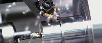
Purpose and scope of application of a metal screw-cutting lathe
The 1K62 lathe is universal and is used for finishing and semi-finishing turning tasks. They cut left and right threads: metric, inch.
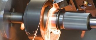
Used for processing hardened workpieces because the spindle provides rigidity to the machine. It produces high-quality cuts with carbide tools due to the large speed range of 1K62.
The device is frontal and it processes short workpieces of large diameter. The machine processes flat cones, because its rear beam can move.
Photo and description of the device
We have just reviewed the general design of the device, and now, along with pictures, the devices of the unit, their properties, features, and meanings in the mechanism will be described in detail.
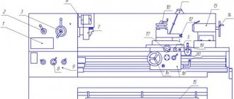
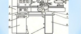
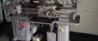
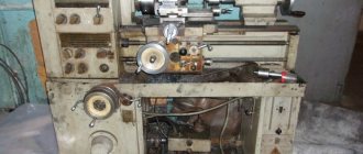
General form
In this picture you can admire the general view of the screw-cutting lathe. The components and various devices discussed earlier are immediately visible.
The weight is more than two tons, and the engine power reaches ten kW. The next picture shows a more detailed drawing, which shows the nodes and their location.
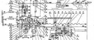
Drawing
This is a general design drawing. It shows all the main components. They will be reviewed one by one very soon. In the upper left corner is the front headstock, in the lower left corner is the gearbox and engine unit.
To the right of the front headstock the chuck is visible, and to the right of the chuck there is a guard, a carriage. Under the numbers 12, 13 in the middle there is a switch, an apron.
Top right - caliper, handle release mechanism, cooling, tailstock, electrical equipment, bed.
Location of controls
The picture shows all the controls and their locations. There are twenty-two organs in total. From the simplest to the very difficult to manage and study.
They control all the mechanisms, thanks to them the unit works and performs tasks. They will not be considered, however, in order to work with the machine you need to know them to avoid accidents.
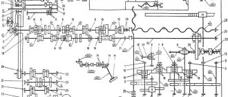
Kinematic diagram
The photo shows a kinematic diagram, that is, a conventional image of the unit, which shows the connection between the elements of the mechanism that transmit movement. The diagram helps to better understand the design of the structure, repair it correctly, and make correct calculations.
Each element in the diagram has its own designation. The symbols must be learned in order to understand the diagram. The shaft is indicated by a straight line, the lead screws by a wavy line, and so on.
Headstock
Previously, the rear one was considered, but there is also a spindle one. It is best seen in the picture above. The design is a unit of grinding machines.
It consists of a supporting spindle, which imparts rotational motion to the grinding wheel. The purpose of the mechanism is to place the spindle and its drive mechanisms.
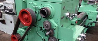
Speed and feed switching device
The gearbox is the main part of the machine spindle drive, designed to transmit movement from the electric motor and change the rotation speed. Typically, the mechanism is mounted in a separate housing and connected by transmission to the spindle.
The feed box provides a large number of feeds in the machine. The second box helps her in this because it changes the speed. The feed mechanism is activated by clutches - friction, cam.
Apron
The picture above shows the apron of the turning unit. The apron converts the rotational movement of the lead screw and roller into the translational movement of the caliper along the frame guides.
The mechanism is usually attached to the front end of the caliper carriage. It has four jaw clutches. Clutches allow the carriage and caliper to make forward and reverse movements.
The apron has a blocking device that prevents the simultaneous activation of longitudinal and transverse feeds.
Caliper
The caliper shown is 1K62. The support is designed to move, fixed in the tool holder of the cutter along, across the axis of the spindle.
It consists of three main units - the carriage, the cross slide, and the cutting slide. In textbooks and books, nodes may be called differently, but they always perform the same functions.
Tailstock
Above is a design called a tailstock. It serves to support the workpiece during processing in the centers; it represents the second support of the unit.
During drilling, the mechanism is attached to the carriage of the caliper to obtain mechanical feed. The mechanism cannot move arbitrarily; it must give the correct position of the center axis.
Electrical circuit diagram
At the top is the electrical circuit diagram. Each unit has this circuit. It shows the main components, parts, and current values.
Without this circuit, the breakdown of the device will be fatal, because it will be impossible to repair it without it. The diagram is most likely in the machine's passport.