A unit designed for welding products is considered to be a semi-automatic welding machine. Such devices can come in various types and shapes. But the most important thing is the inverter mechanism. It is necessary that it be of high quality, multifunctional and safe for the consumer. Most professional welders do not trust Chinese products and make the devices themselves. The manufacturing scheme for homemade inverters is quite simple. It is important to consider for what purposes the device will be manufactured.
There are inverters for:
- Welding using flux-cored wire;
- Welding with various gases;
- Welding under a thick layer of flux;
Sometimes, to achieve a high-quality result and obtain an even weld, the interaction of two devices is necessary.
Inverter devices are also divided into:
- Single-hull;
- Double-hull;
- Pushing;
- Pulling;
- Stationary;
- Mobile, which includes a trolley;
- Portable;
- Designed for beginner welders;
- Designed for semi-professional welders;
- Designed for professional craftsmen;
Inverter circuit:
What will you need?
A homemade device, the circuit of which is very simple, includes several main elements:
- A mechanism with the main function responsible for controlling the welding current;
- Mains power supply;
- Special burners;
- Convenient clamps;
- Sleeves;
- Cart;
Scheme of welding using a semi-automatic device in a protective gas environment:
The master will also need:
- A mechanism that provides wire feeding;
- A flexible hose through which wire or powder will be supplied to the weld under pressure;
- Bobbin with wire;
- Special control device;
Tools and materials
To make a semi-automatic welding unit from an inverter (AC-to-DC converter) with your own hands, you need to prepare the required components and equipment.
- Inverter with an output current of 150 A.
- Filler material (additive) supply device.
- Gas burner gun.
- A supply hose, which will become a guide channel for the filler material going to the area to be welded.
- Hose for supplying protective gas mixtures to the welded area.
- Reel (reel) with filler material (wire).
- Electronics unit for monitoring the activities of a semi-automatic welding unit. Here the electric current strength, voltage and operating speed are adjusted.
- Scheme of a semi-automatic welding device.
Principle of operation
The operating principle of the inverter includes:
- Adjusting and moving the burner;
- Control and monitoring of the welding process;
When the unit is connected to the electrical network, a conversion of alternating current to direct current is observed. For this procedure you will need an electronic module, special rectifiers and a high-frequency transformer. For high-quality welding, it is necessary that the future unit has parameters such as the feed speed of the special wire, current strength and voltage in identical balance. For these characteristics, you will need an arc power source that has current-voltage readings. The length of the arc must be determined by the specified voltage. The wire feed speed directly depends on the welding current.
Homemade device diagram:
The electrical circuit of the device provides for the fact that the type of welding greatly influences the progressive performance of the devices as a whole.
Electrical diagram of a homemade device:
DIY semi-automatic - detailed video
Semi-automatic welding from an inverter
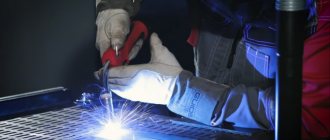
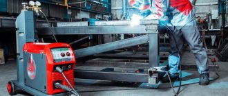
To convert an inverter into a semi-automatic welding machine, you will need three main modules. Electric, providing current from the inverter and welding mode, a mechanism for supplying wire and a torch with a nozzle. The burner creates a gaseous environment in the form of a cloud of protective inert gas that prevents oxidation of the molten metal. For this, a carbon dioxide cylinder is used, which is connected to the device using a hose and an inlet fitting. If you use filler material with a special coating that forms a protective environment, you can do without a cylinder. This method is common among craftsmen.
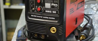
Figure 2 - Semi-automatic inverter
The torch replaces the electrode holder familiar to welders. Externally, it looks like a pistol grip with a key that provides wire feeding.
It moves along a thin channel passing inside the rubberized sleeve connecting the semiautomatic device to the burner. The channel for supplying gas during welding is located in the same sleeve and ends with a nozzle at the end of the torch.
For high-quality welding, a semi-automatic inverter must maintain a constant voltage at the output, like factory equipment.
Required tools and materials
To create a semi-automatic machine from an inverter with your own hands, you will need to prepare the necessary components and equipment.
List of tools and materials:
- Inverter with output current from 150 A.
- A wire feed mechanism that moves it without jerking or slowing down.
- Gas burner for melting the bath.
- A supply hose that will serve as a guide sleeve for the wire moving towards the work area.
- A gas hose that supplies protective carbon dioxide to the welding site.
- Spool of filler wire.
- Electronics unit for controlling the operation of a semi-automatic welding machine. Here the current strength, voltage and operating speed are adjusted.
- Semi-automatic welding circuit diagram.
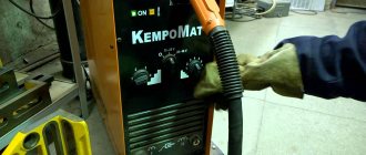
Figure 3 - Diagram of a semi-automatic welding machine
Most of the components are used without significant changes. The wire feed mechanism will require modifications so that the process matches the melting speed. The device must be adjustable, because the speed varies depending on the type of materials being welded, the type and diameter of the wire.
Inverter conversion process
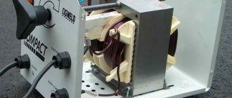
In a finished inverter, you first need to remake the transformer included in it. It is covered with an additional layer consisting of copper strip and thermal paper.
Ordinary copper wire cannot be used for a welding transformer. When welding, it overheats greatly and can stop the operation of the entire semi-automatic welding machine.
The secondary winding of the transformer will also require intervention. It is covered in three layers of tin, insulated with fluoroplastic tape. The ends of the applied winding are soldered. As a result of manipulation, the conductivity increases significantly.
An important element is a fan that will cool the device, protecting it from overheating.
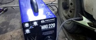
Figure 4 - Inverter winding
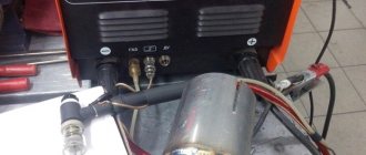
An inverter for manual welding can easily be converted into a power source for a semi-automatic machine. A functioning device does not need to be disassembled, but all additional equipment is placed in a separate housing. It houses a freely rotating spool of welding wire and a pulling mechanism. The side panel displays a wire speed regulator and a socket for connecting a hose.
An old computer system case will do just fine. It turns out compact and neat.
The current parameters can be adjusted on the inverter, then the “positive” terminal is connected to the workpiece from it.
The “negative” contact is removed from the inverter and goes into the new housing. Here it is connected to the sleeve terminal. It is important that the welding wire is connected to this potential.
The gas hose running from the cylinder to the burner is also attached to the housing. If you use the valve from a car windshield wiper, the gas supply will be adjusted.
The above arrangement is simple to implement, and the inverter can be simultaneously used for manual arc welding and as a power source for a home-made semi-automatic machine.
Wire feeder assembly
The feed mechanism is necessary for the uniform flow of electrode wire at the required speed into the welding zone.
Consumables are selected based on the type of metal and the purpose of welding work. Material and size may vary. Therefore, the device must be adjustable to suit different types of wire and welding conditions. Running wire diameters: 0.8; 1; 1.2 and 1.6 mm.
The wire drawing mechanism is purchased ready-made in the electrical goods department or made from improvised materials. For assembly you will need a motor from car windshield wipers, three bearings, a pressure spring and a roller mounted on the electric motor shaft. And also plates at least 1 cm thick of a suitable size on which the bearings are mounted.
Figure 5 — Diagram of the electric motor speed controller
The components are placed on a textolite plate with a thickness of at least 5 mm. The wire is inserted between the bearing and the roller. The exit location should coincide with the fastening of the end of the supply hose into which it is pulled. The wire is wound evenly and carefully onto the reel, because the quality of the future connecting seam depends on this. The coil is installed on a homemade support and fixed. During operation, the wire will unwind and flow to the joint to be welded. With the help of the feeding mechanism, it is possible to simplify and speed up welding work and make it more productive.
Figure 6 — Feeding mechanism
Burner assembly design
A welding torch is a welder’s working tool for making a weld in a protective gas environment.
It lasts no more than six months and is considered a consumable item. The burners operate on the same principle, although they differ in size, materials, maximum temperature, power and gas supply mechanism.
Structural elements:
- base with handle;
- nozzle;
- holder;
- tip;
- insulating sleeve.
Figure 7 — Burner assembly design
Welding is accompanied by overheating of the torch elements. The nozzle and current carrying tip suffer the most. The duration of operation will depend on the material of the tip. Copper is widely used, and in more expensive versions, tungsten. The average tip life is 200 hours. They are made quick-change because they have to be changed frequently.
The handle is made of heat-resistant insulating material, which reliably protects the welder from electric shock. On the torch handle, a button controls the on and off supply of consumables and protective gas. A feeding sleeve with a standard length of 2.5–7 m extends from the handle. The choice of sleeve length depends on the type of work performed.
It is not recommended to allow excess sleeves folded into rings. The output coil voltage causes them to become very hot, which can cause a short circuit.
Figure 8 — Gas burner design
There is a wide selection of gas burners on the market. The models are characterized by the following parameters:
- load current;
- cooling method: air or water;
- the length of the sleeve;
- connection with a plug or Euro connector;
- control method: universal, push-button or valve.
The burner should be compact and lightweight. For a homemade device, a plug connector is sufficient. The plastic case must be durable and ergonomic. The burner is selected according to current parameters that are lower than those of a semiautomatic device.
To ignite the arc, it is necessary that the wire extends beyond the edge of the burner by 10–15 cm.
The supply of consumables is turned on by pressing a button on the torch, which is in the hands of the welder. The toggle switch on the body opens and closes the gas supply to the welding zone.
Control and Power
The semi-automatic device is controlled by a microcontroller.
It is also responsible for converting and stabilizing current. The power supply to the wire pulling mechanism and the valve that turns off the gas is supplied with a voltage of 12 V. To do this, you will need to install a small transformer with a rectifier. Switching between the motor and the valve occurs through a 12 V intermediate auto relay.
Assembly of the unit
The assembly instructions will help you make a quality semi-automatic welding machine. The work is carried out in the following sequence:
- Connect the inverter to power and control devices.
- Thread the wire into the feed mechanism and check for smooth movement.
- Set the required wire feed speed.
- Connect the burner to a hose, which is connected to the feeder.
- Connect a gas cylinder with a reducer and a pressure gauge to the burner.
- Turn on the inverter and feeder.
- Check the flow of gas and wire. After gas supply, the delay in wire movement should be 1–2 s. It enters a ready-made protective environment, otherwise it will stick.
When preparing a home-made semi-automatic machine for the first start-up, you need to take care of cooling the assembled semi-automatic welding machine so that it does not overheat. For this purpose, input and output rectifiers and power switches are mounted on radiators. On the inverter body where the radiator is located, that is, in the most heated zone, it is recommended to install a temperature sensor that will de-energize the device if it overheats.
After this, connect the power part to the control unit, and then turn on the semi-automatic device to the power supply. When the mains lights come on, the inverter needs to be tested. At the output of the device, a current is measured, which should not exceed 120 A. If its value is less, this means that a voltage below 100 V is supplied to the equipment through the wires. In this case, the current is changed and the voltage is controlled, achieving the desired parameters. In this case, the inverter should not overheat.
Under load, the semi-automatic device is checked as follows. The welding wires are connected to a rheostat designed for a current of 60 A and a resistance of at least 0.5 Ohm. The current supplied to the burner is controlled with an ammeter. If the current strength differs from the norm, change the resistance value.
After turning on the assembled semi-automatic device, the indicator should show a current strength of 120 A. This figure confirms the correctness of the work. If eights are displayed, then the reason is insufficient voltage in the supply wires. Welding inverters operate in the operating current adjustment range of 20–160 A.
Control during work
The performance and service life of the semi-automatic device depends on compliance with the temperature regime. The normal temperature on radiators is 75 °C. When overheating, breakdown or short circuit occurs, a sound signal appears. The electronic control unit will automatically reduce the operating current to 20 A, the sound signal will remain until the situation stabilizes. An error in the system is accompanied by the Err code on the indicator.
Created plan
Any scheme of a homemade device provides a separate sequence of operation:
- At the initial level, it is necessary to ensure preparatory purging of the system. It will accept the subsequent supply of gas;
- The arc power source must then be started;
- Feed wire;
- Only after all actions have been completed will the inverter begin to move at the specified speed.
- At the final stage, the seam should be protected and the crater welded;
Assembly of a rectifier based on a diode bridge
Diode bridge circuit
The manufacture of a homemade semi-automatic device powered by a household AC network requires the installation of a diode bridge. Equipping a single-phase transformer with a secondary voltage rectification device graphically looks like a symmetrical transfer of the lower sinusoids relative to the abscissa axis to the upper quadrants of the coordinate system.
After the rectifying device, the voltage ripple reaches 100 Hz. Twice during a period, an uncontrolled voltage drop from maximum to zero is not capable of maintaining stable combustion and ignition of the welding arc. This flaw is eliminated by a filter, a device designed to smooth out surges in voltage ripple.
Preparing the transformer
Your attention must be paid to the feeding mechanism. Using this device, the electrode wire must be fed. Due to the fact that this mechanism breaks down most often, high-quality calculations should be made. It is important to note that an increase in current in most cases leads to fire of the electrode. This causes severe damage to the product. But if the current is very weak, then it will not be possible to make a full-fledged unit. The resulting weld will be unreliable. Therefore, at this stage of preparation it is necessary to correctly perform all calculations.
Feeder
The electrode wire must be fed continuously and evenly - then the welding will be of high quality. The feed speed must be adjusted. There are three options for making the device:
- Buy a fully assembled mechanism. Expensive, but fast.
- Buy feed reels only.
- Do it all yourself.
If the third option is chosen, you will need:
- two bearings, guide roller, tension spring;
- motor for feeding wire - a motor from windshield wipers will do;
- metal plate for fastening the mechanism.
One pressure bearing - it should be adjustable, the second serves as a support for the roller. Manufacturing principle:
- holes are made on the plate for the motor shaft and for mounting bearings;
- the motor is fixed behind the plate;
- a guide roller is put on the shaft;
- bearings are fixed at the top and bottom;
It is best to place the bearings on metal strips - one edge is bolted to the main plate, and a spring with an adjusting bolt is connected to the other.
The completed mechanism is placed in the housing so that the rollers are located in line with the burner connector, i.e., so that the wire does not break. A rigid tube must be installed in front of the rollers to align the wire.
Power supply
Repair or fabrication of a structure includes a power source. Such a device can be a rectifier, inverter or transformer. It is this part that affects the volume and cost of the welder. Inverter power supplies are considered to be the most professional and high-quality devices.
Power supply diagram:
Control board
To create an inverter, a special control board is required. This device must have the following components installed:
- A master oscillator including a galvanic isolation transformer;
- The node with which the relay is controlled;
- Feedback blocks responsible for mains voltage and supply current;
- Thermal protection block;
- Antistick block;
Control unit printed circuit board:
Typical faults
The main faults are immediately visible. If the seam turns out to be porous and dark, the balloon should be replaced. These are signs of moisture in the gas. A large number of sparks occur when operating in one mode, when the cylinder is empty and the pressure - gas flow - decreases.
The inverter operates with the greatest load. It has a complex electronic board, a cooling system, and the operation of all other mechanisms is tied to it. Therefore, the inverter breaks down more often than other components of a semi-automatic device.
Unauthorized cycle interruption
The reason for interruption of the welding process may be uneven wire feed. When consumables move jerkily. In this case, the channel should be replaced with a new one that is smooth inside. You should check the operation of the tension mechanism and change the pressure force of the rollers. If necessary, replace the spare part or the entire assembly.
If there is a breakdown in the high-voltage coil winding, the welding cycle is interrupted and does not resume. The windings should be ringed and the unsuitable part should be replaced.
Poor contacts may be to blame for interruptions in the operation of the semi-automatic machine. If they are oxidized or the connection is loose, the current will flow intermittently or disappear. The contacts should be cleaned, coated with a special conductive lubricant and tightened.
The inverter welding machine begins to pull at a temperature of -5⁰. If it is lower, it simply stops working, interrupting the welding cycle. It is necessary to check under what conditions the device is operated. If the reason is cold, then it is enough to move the inverter to a warm room, give it time to warm up, and the semiautomatic device will work normally.
Strong rattling and humming noise
The device begins to hum when the transformer is overloaded. This occurs when welding with a wire or electrode of a larger diameter, for which the semi-automatic machine is designed. A hum can occur when there is a heavy load on the windings due to a strong drop in the mains current. You should check the passport to see what maximum diameter of the consumable is allowed and the minimum voltage with which this device can operate.
Rattling accompanies the operation of a semi-automatic welding machine in the event of poor contacts and sparking at the junction of different components. It is necessary to replace the insulation with a new one and secure the contacts. You may need a dielectric insert between the coils to ensure they do not touch or short out.
Device overheating
Most often, overheating of a semi-automatic welding machine causes:
- work at increased conditions;
- non-compliance with the frequency of work and rest of equipment;
- fan malfunction;
- low voltage in the network;
- dust covered the microcircuits and air cooling elements.
When operating the equipment, you should first study its technical characteristics and do not overload the semi-automatic device. All passports indicate the current limit values and operating mode as a percentage relative to the operating hour. For example, 40% means that every 25 minutes the device should rest for 35 minutes. Inverter semi-automatic machines usually cool quickly and have an operating mode of 50% and even 60%. But you still need to stop.
During a monthly inspection, the direction of rotation of the fan is checked; it should drive air inside the case. If dust settles on the fins of refrigerators and circuit boards, the equipment will heat up.
When the network voltage is low, the device operates with increased load. The windings and the entire converter heat up. In the ranking of semi-automatic devices operating at low currents, the inverter is in the lead. The transformer cannot withstand sagging below 185V.
Repair/modification of electrode wire feed speed device
Inverters are considered reliable devices. But if care is not taken care of, the devices may fail. The devices may require repairs. In most cases, the main cause is a broken regulator. When the first problems occur, the breakdown affects the further operation of the device. Therefore, in order to avoid future repairs, you should devote as much time as possible to high-quality assembly of the device.
The unit diagram includes a pressure roller. It is equipped with a special wire pressure level regulator. The unit also contains a wire feed roller, which has two small recesses. The welding wire should come out of them. The use of wire with a diameter of up to 1 mm is allowed. Immediately after the regulator there is a solenoid that controls the gas supply.
The regulator is considered a large element. It is secured with small bolts. Therefore, the fastening is extremely unreliable. The unit may warp, which may lead to malfunction. It is because of this reason that the device often breaks down and requires additional repairs.
Remodeling methods
To begin with, let's consider possible options for converting an inverter into a semi-automatic welding machine.
To create a semi-automatic device, you will definitely need a so-called head unit. This is, in fact, a welding machine, which will form the operating parameters for the occurrence of an arc discharge. Not every inverter model is suitable as such a head unit.
It is necessary to choose a sufficiently powerful welding machine. Its current-voltage characteristics can be changed using a pulse-width modulation controller. However, firstly, not every home craftsman has such a device. Secondly, the measurement process is very long and labor-intensive. Finally, only a person with a sufficiently high level of knowledge in electrical engineering can carry out all the research.
Since the option with a PWM controller will not be available to the average welder, it is recommended to take a simpler route. Firstly, the selected donor device must normally perform all necessary operations. Secondly, to create a homemade semi-automatic you will need a choke. This part, intended for fluorescent lamps, can be purchased at any spare parts store. The inductor output voltage is used as a feedback input. How exactly to make a connection diagram and carry out the necessary installation operations is shown in the video below.
This option for creating a homemade semi-automatic machine is suitable only for happy owners of high-quality equipment. Namely, inverters capable of operating in a strictly specified current-voltage characteristic mode. Welders of this class are expensive, but they are most suitable for solving the task.
To make your own semi-automatic device, you will need:
- buy a wire feeder, complete with all the necessary wires and switching connectors;
- connect the feed mechanics to the inverter welding machine;
- select the current-voltage characteristic to work with a specific type of wire.
Wire feeder from Aliexpress
In essence, the feed mechanism acts as an attachment that expands the capabilities of the welding inverter. However, such a scheme has increased reliability and does not require special knowledge from the user. In addition, the resulting semi-automatic machine shows the maximum level of flexibility and unpretentiousness: it can be quickly configured to work with a specific material and wire.
This method will require considerable preparation from the user. Firstly, he will need to find a non-average inverter welding machine of suitable power. It is necessary to select the simplest possible donor of a certain class. The ideal device would be one that:
- there is a shunt at the output;
- a current transformer is used in the primary conversion block;
- ZX-7 layout.
It is recommended to choose devices without additional control options and functionality to make the life of the welder easier. The inverter should not have any hot starts, simple ignition, or arc forced.
To create your own homemade semiautomatic device, you will need to accurately set the current-voltage parameters of the selected inverter. You will also need to adjust the current increase. The order and list of required work is not universal. It differs for different inverter models.
Volt-ampere characteristics of the welding inverter
DIY choke
In order to make a choke, you will need a transformer, an enamel wire with a diameter of more than 1.5 mm. Insulation is wound between the layers. Using an aluminum bus with dimensions of at least 2.5x4.5 mm, 24 turns are wound. The remaining ends of the bus remain 30 cm each. The core is laid using pieces of textolite with a gap of at least 1 mm. It is also allowed to wind the inductor on iron from an old tube color TV. But such a device can only have one coil. Such a device can stabilize the welding current. The finished product must output a minimum of 24 V at 6 A.
Inverter setup
How to make an antenna for digital TV with your own hands
To ensure high-quality operation of a semiautomatic device with small dimensions, it is best to use toroidal type transformers. They have the highest efficiency.
The transformer for operation of the inverter is prepared as follows: it must be wrapped with a copper strip (40 mm wide, 30 mm thick), protected with thermal paper, of the required length. The secondary winding is made of 3 layers of sheet metal, insulated from each other. To do this, you can use fluoroplastic tape. The ends of the secondary winding at the output must be soldered. In order for such a transformer to operate smoothly and not overheat, it is necessary to install a fan.
Transformer winding diagram
Work on setting up the inverter begins with de-energizing the power section. Rectifiers (input and output) and power switches must have radiators for cooling. Where the radiator is located, which heats up the most during operation, it is necessary to provide a temperature sensor (its readings during operation should not exceed 75 0C). After these changes, the power section is connected to the control unit. When switched on. The network indicator should light up. You need to check the pulses using an oscilloscope. They should be rectangular.
Their repetition rate must be in the range of 40 ÷ 50 kHz, and they must have a time interval of 1.5 μs (the time is adjusted by changing the input voltage). The indicator should show at least 120A. It would not be superfluous to check the device under load. This is done by inserting a 0.5 ohm load rheostat into the welding leads. It must withstand a current of 60A. This is checked using a voltmeter.
A properly assembled inverter when performing welding work makes it possible to regulate the current in a wide range: from 20 to 160A, and the choice of operating current depends on the metal that needs to be welded.
To make an inverter with your own hands, you can take a computer unit, which must be in working condition. The body needs to be strengthened by adding stiffeners. An electronic part is mounted in it, made according to Sanych’s scheme.
Welding torch
This device is designed to supply electrode wire, carbon dioxide and arc voltage to the required welding area. The purpose of the device is to close the circuit, which ensures the supply of welding wire to the shielding gas.
Welding torch:
For the best quality effect, it is recommended to purchase a ready-made gun. The device must include hoses for supplying welding wire and shielding gas.
Semi-automatic Sanych
To make the transformer, Sanych used 4 cores from TS-720. The primary winding was wound with copper wire Ø 1.2 mm (number of turns 180+25+25+25+25), for the secondary winding I used an 8 mm2 busbar (number of turns 35+35). The rectifier was assembled using a full-wave circuit. For the switch I chose a paired biscuit. I installed the diodes on the radiator so that they would not overheat during operation. The capacitor was placed in a device with a capacity of 30,000 microfarads. The filter choke was made on a core from TS-180. The power part is put into operation using a TKD511-DOD contactor. The power transformer is installed TS-40, rewound to a voltage of 15V. The roller of the broaching mechanism in this semi-automatic machine has a Ø 26 mm. It has a guide groove 1 mm deep and 0.5 mm wide. The regulator circuit operates at a voltage of 6V. It is sufficient to ensure optimal feeding of the welding wire.
How other craftsmen improved it, you can read messages on various forums dedicated to this issue and delve into the nuances of manufacturing.
Cart
The cart can be made by yourself. The use of ready-made structures is also permitted. You can make single-level, two-level and three-level products. For convenience, tools and materials that will be needed for work are stored on the upper level. For easy movement, the cart includes wheels with a diameter of at least 5 cm.
Homemade cart with several variations:
Welding modes in carbon dioxide:
A semi-automatic device differs from a conventional device in its wire feed mechanism. Therefore, such a unit is considered the most complex device. Repair will be necessary if the feed mechanism breaks down.
Another useful manufacturing option
How to adjust the feed mechanism?
Schemes of homemade welding machines imply the presence of a special welding wire feeding mechanism for semi-automatic machines. If there is no blank for this element, you can assemble it yourself according to the drawings.
To do this, you will need to take two bearings, the size of which must correspond to standard size 6202, you will also need an electric motor from car wipers, and the smaller its size, the better.
When selecting a welding machine and its compliance with the semi-automatic welding circuit, it is necessary to carefully check that it rotates strictly in one direction. In addition, you will need to take a roller with a diameter of exactly 25 mm. It is placed over the threads on the electric motor shaft. All non-standard structural elements are produced independently - this will make it much easier in the future to repair semi-automatic welding machines with your own hands.
The feed mechanism includes two plates on which bearings are mounted. Between them there is a roller with an electric motor connected to it. The plates are compressed by a spring; the same element of the homemade feed mechanism circuit allows the bearings to be pressed against the roller. The mechanism is assembled on a special textolite plate, its thickness is about 5 mm. This is done in such a way that the welding wire comes out of the mechanism in the area of the connector.
This connector, in turn, will connect to the welding sleeve mounted on the front of the housing. A coil with wound wire is connected to the same plate. In order for the reel to hold well on the feed mechanism, a special shaft is made under it, which is attached perpendicular to the textolite plate. A thread should be cut from the edge of the shaft so that the coil fits onto it as tightly as possible.
The schematic diagram of a semi-automatic welding machine, manufactured independently, is practical, reliable and economical. It is worth noting that the design will probably not look very attractive, but in terms of its operational characteristics it will be practically no different from professional industrial equipment.
All elements located in the feed mechanism are designed for a standard reel. However, this design has one serious drawback - welding work will be carried out without gas.
Converting a welding inverter into a semi-automatic machine
To make a semi-automatic welding inverter, you need to subject the device to some manipulations. The device is wrapped in copper strip with thermal paper winding. It is important to note that ordinary thick wire will not work. It will get very hot. The cooling system may not be able to cope with the load, which will lead to severe overheating of the device.
The secondary winding should consist of three layers of tin. Each layer should be carefully insulated. To do this, use fluoroplastic tape. The ends of the winding must be soldered together. This procedure allows you to increase the conductivity of currents.
Oscillogram of welding voltage and current on reverse and direct polarity:
Any homemade device does not respond well to the presence of dirt and dust. Therefore, such devices should be cleaned at least once every 4-6 months. The intensity of cleaning should depend on the number of uses. Otherwise, the device will have to be repaired annually.
Approximate modes for welding butt seams using a semi-automatic machine:
The main advantage of such devices is considered to be low weight. It is also possible to use both AC and DC power. The units can weld non-ferrous metals, as well as cast iron. The disadvantages include the low temperature range. Do-it-yourself semi-automatic welding cannot be used at temperatures below 15°C. Therefore, such devices are not suitable for cold regions and for the winter period. Basically, such inverters are used outdoors in the summer or indoors. Homemade structures are perfect for welding small structures at home. For professional welding and for wide production, it is recommended to buy ready-made inverters.
How to monitor the correct operation of equipment
In order for the semi-automatic welding machine that you assembled with your own hands to serve you for a long time, it is better to constantly monitor the temperature conditions of the inverter. To carry out such control, you need to press two buttons simultaneously, after which the temperature of the hottest inverter radiator will be displayed on the indicator. The normal operating temperature is considered to be one whose value does not exceed 75 degrees Celsius.
If this value is exceeded, then, in addition to the information displayed on the indicator, the inverter will begin to emit an intermittent sound signal, which should be noted immediately. In this case (as well as if the temperature sensor breaks or shorts), the electronic circuit of the device will automatically reduce the operating current to 20A, and a sound signal will be emitted until the equipment returns to normal. In addition, a malfunction of self-made equipment may be indicated by an error code (Err) displayed on the inverter indicator.
Setting the welding mode on the Resanta inverter