The quality of the weld depends largely on the characteristics of the electric arc. For each thickness of metal, depending on its type, a certain strength of welding current is required.
In addition, the current-voltage characteristic of the welding machine is important; the quality of the electric arc depends on it. Cutting metal also requires its own electric current values. That is, any welding machine must have a regulator that controls the welding power.
Methods of regulation
The current can be controlled in different ways. The main methods of regulation are:
- introducing a resistive or inductive load into the secondary winding of the welding machine;
- changing the number of turns in the secondary winding;
- change in the magnetic flux of the welding machine;
- use of semiconductor devices.
There are many schematic implementations of these methods. When making a welding machine with your own hands, everyone can choose a regulator according to their taste and capabilities.
Resistor or inductance
Adjusting the welding current using a resistance or inductor is the simplest and most reliable. A powerful resistor or inductor is connected in series to the welding electrode holder. Due to this, the active or inductive resistance of the load changes, which leads to a voltage drop and a change in the welding current.
Regulators in the form of resistors are used to improve the current-voltage characteristics of the welding machine. A set of powerful wire resistances or one resistor made of thick nichrome wire in the form of a spiral is used.
To change the resistance, they are connected to a specific turn of wire using a special clamp. The resistor is made in the form of a spiral to reduce its size and ease of use. The resistor value should not exceed 1 ohm.
Alternating current at certain times has zero or close to it values. At this time, a short-term arc extinguishing occurs. When the gap between the electrode and the part changes, sticking or complete extinguishing may occur.
To soften the welding mode and, accordingly, obtain a high-quality seam, a regulator is used in the form of a choke, which is connected in series with the holder in the output circuit of the device.
The additional inductance causes a phase shift between the output current and voltage. At zero or close to zero values of alternating current, the voltage has a maximum amplitude and vice versa. This allows you to maintain a stable arc and ensures reliable ignition.
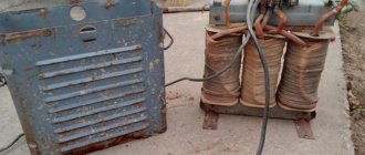
The choke can be made from an old transformer. Only its magnetic core is used, all windings are removed. Instead, 25-40 turns of thick copper wire are wound.
This regulator was widely used when using AC transformer devices due to its simplicity and availability of components. The disadvantages of the welding current throttle regulator are the small control range.
Changing the number of turns
With this method, the arc characteristics are adjusted by changing the transformation ratio. The transformation ratio can be changed by additional taps from the secondary coil. By switching from one tap to another, you can change the voltage in the output circuit of the device, which leads to a change in arc power.
The regulator must withstand high welding current. The disadvantage is the difficulty of finding a switch with such characteristics, a small range of adjustments and discreteness of the transformation ratio.
Specifications
Despite the different types of inverters presented on the electrical products market, they all have the same parameters and characteristics. The difference lies only in the magnitude of these indicators, which makes it possible to choose the most suitable device.
Among them are the following:
- Welding current with a wide range of adjustments. For professional devices it is larger, and for household devices it is less.
- Duration of continuous operation at a certain value of the selected welding current.
- Presence of idling, high power consumption of the inverter.
- Dependence on voltage and other parameters of the electrical network.
All main indicators are directly related to the characteristics of the rectifier installed at the input and to the frequency converter itself. Power matters a lot. Industrial devices are produced quite powerful - up to 20 kW. Such equipment is not used in everyday life, since ordinary networks simply cannot withstand high loads. The cost of a particular device also depends on the amount of power.
All types of inverters of modern modifications can perform several basic operations:
- Welding in semi-automatic mode using inert gases or carbon dioxide.
- Manual arc welding with conventional electrodes.
- Argon arc welding in a protective gas environment. To perform this function, the devices can be equipped with additional options - non-contact arc ignition, gradual reduction of current, adjustable gas blowing duration, pulse mode and others.
Magnetic flux change
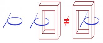
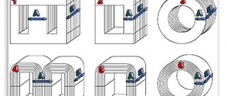
This control method is used in transformer welding machines. By changing the magnetic flux, the efficiency of the transformer is changed, this in turn changes the value of the welding current.
The regulator operates by changing the gap of the magnetic circuit, introducing a magnetic shunt or moving the windings. By changing the distance between the windings, the magnetic flux is changed, which accordingly affects the parameters of the electric arc.
On older welding machines there was a handle on the lid. As it rotated, the secondary winding was raised or lowered by a worm gear. This method has practically become obsolete; it was used before the proliferation of semiconductors.
Semiconductor devices
The creation of powerful semiconductor devices capable of operating with high currents and voltages has made it possible to develop a new type of welding machines.
They have become capable of changing not only the resistance of the secondary circuit and phase, but also changing the frequency of the current and its shape, which also affects the characteristics of the welding arc. A traditional transformer welding machine uses a welding current regulator based on a thyristor circuit.
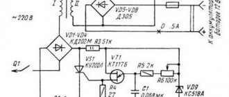
The principle of operation of a thyristor
The regulator parts are connected both in parallel and counter to each other. They are gradually opened by current pulses, which are formed by transistors vt2 and vt1. When the device starts, both thyristors are closed, C1 and C2 are capacitors, they will be charged through resistor r7. At the moment when the voltage of any of the capacitors reaches the avalanche breakdown voltage of the transistor, it opens, and the discharge current of the joint capacitor flows through it. After the transistor opens, the corresponding thyristor opens and connects the load to the network. Then the opposite half-cycle of the alternating voltage begins, which implies the closing of the thyristor, then a new cycle of recharging the capacitor follows, this time in the opposite polarity. Then the next transistor opens, but again connects the load to the network.
Adjustment in inverters
Welding inverters are the most modern devices for electric arc welding. The use of powerful semiconductor rectifiers at the input of the device and the subsequent transformation of alternating current into direct current, and then into high-frequency alternating current, made it possible to create devices that are compact and powerful at the same time.
In inverter devices, the main regulator is changing the frequency of the master generator. For the same transformer size, the conversion power directly depends on the frequency of the input voltage.
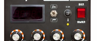
The lower the frequency, the less power is transferred to the secondary winding. The adjustment resistor knob is displayed on the front panel of the inverter. When it rotates, the characteristics of the master oscillator change, which leads to a change in the switching mode of the power transistors. The result is the required welding current.
When using inverter semi-automatic welding machines, the settings are the same as when using manual welding.
In addition to external regulators, the inverter control unit contains many different control elements and protections that ensure a stable arc and safe operation. For a novice welder, the best choice would be an inverter welding machine .
Semi-automatic welding
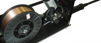
The semi-automatic machine consists of two main components:
- Wire feed unit. It feeds the wire into the welding zone and is additionally equipped with a shielding gas supply device.
- Arc power device. It is used as a welding rectifier or inverter.
Reference! The current of the semi-automatic device is regulated in the device feeding the arc.
Application of thyristor and triac circuits
After the creation of powerful thyristors and triacs, they began to be used in output current regulators in welding machines. They can be installed in the primary winding of the transformer or in the secondary winding. The essence of their work is as follows.
The control contact of the thyristor receives a signal from the regulator circuit that opens the semiconductor. The duration of the signal can vary within wide limits, from 0 to the duration of the half-cycle of the current flowing through the thyristor.
The control signal is synchronized with the regulated current. Changing the signal duration causes the beginning of each half-cycle of the welding current sinusoid to be cut off. The duty cycle increases, as a result the average current decreases. Transformers are very sensitive to such control.
This regulator has a significant drawback. The time of zero values increases, which leads to uneven arc and its unauthorized extinguishing.
To reduce the negative effect, it is additionally necessary to introduce chokes, which cause a phase shift between current and voltage. In modern devices this method is practically not used.
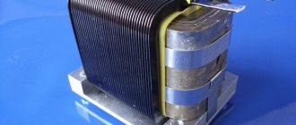
How to make a throttle yourself?
It is quite possible to make your own throttle at home. This occurs when there is a straight coil with a sufficient number of turns of the desired cord. Inside the coil are straight metal plates from the transformer. By choosing the thickness of these plates, it is possible to select the starting reactance.
Let's look at a specific example. A choke with a coil with 400 turns and a cord with a diameter of 1.5 mm is filled with plates with a cross-section of 4.5 square centimeters. The length of the coil and wire should be the same. As a result, the 120 A transformer current will be reduced by half. Such a choke is made with a resistance that can be changed. To carry out such an operation, it is necessary to measure the deepening of the passage of the core rod into the coil. Without this tool, the coil will have little resistance, but if the rod is inserted into it, the resistance will increase to its maximum.
A choke that is wound with the correct cord will not overheat, but the core may experience strong vibration. This is taken into account when screeding and fastening iron plates.