The problem is that the voltage in the electrical network changes depending on its load, and for the correct operation of most electricity consumers it is necessary to find the supply voltage in a certain range so that it does not exceed or fall below a certain permissible limit.
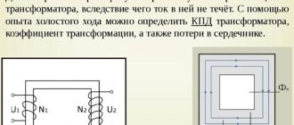
Therefore, we need some ways of regulating, regulating, regulating the mains voltage. One of the best ways is to change the transformation ratio as needed by decreasing or increasing the number of turns of the primary or secondary winding of the transformer according to the well-known formula: U1 / U2 = N1 / N2.
To adjust the voltage on the secondary windings of transformers in order to maintain the correct voltage for consumers, some transformers have the ability to change the turns ratio, that is, adjust the transformation ratio in one direction or another.
The vast majority of modern power transformers are equipped with special devices that allow you to adjust the transformation ratio, that is, add or subtract turns in the windings.
This adjustment can be made either directly under load, or only when the transformer is grounded and completely de-energized. Depending on the importance of the object and the frequency with which these adjustments are necessary, there are more or less complex systems for switching turns in the windings: those that perform switching without load - "switching without excitation" or with load switching. — “settlement under load.” In both cases, the transformer windings have branches between which switching occurs.
Switching without excitation
Non-excited switching occurs from season to season, this is a planned seasonal shift change when the transformer is taken out of service, which obviously will not work often. The transformation coefficient has changed, more or less within 5%.
On high-power transformers, switching is performed using four sockets, on low-power transformers - only using two. This type of switching is associated with a power outage of consumers and is therefore performed quite rarely.
Often sockets are made on the higher voltage side, where there are more turns and the adjustment is more accurate, besides, the current is less and the switch is more compact. The change in magnetic flux at the moment of such switching of turns on a step-down transformer is very small.
If it is necessary to increase the voltage on the lower voltage side of the step-down transformer, the turns on the primary winding are reduced; if it is necessary to decrease them, they are added. If the adjustment is made from the load side, then increase the voltage of the turns of the secondary winding to increase it, and decrease it to decrease it. A switch used on a de-energized transformer is colloquially called an anzapfa.
The contact point, despite the fact that it is made of a spring, undergoes slow oxidation over time, which leads to an increase in resistance and overheating. To prevent the occurrence of this harmful cumulative effect, so that the gas protection does not work due to oil decomposition under the influence of excessive heat, the switch is regularly serviced - twice a year, the correct setting of the transformation ratio is checked, when switching the anapf to all positions, in order to remove the oxide film before final installation the required degree of transformation.
Also measure the DC resistance of the windings to ensure the quality of the contact. This procedure is also carried out for transformers that have not been used for a long time before being used.
Load control
Online switching is performed automatically or manually, directly under load, where the voltage varies significantly at different times of the day. High and low power transformers, depending on the voltage, have on-load tap-changers of different ranges - from 10 to 16% with a step of 1.5% on the higher voltage side - where the current is less.
Here, of course, there are some difficulties: on a powerful transformer it is simply impossible to break the circuit, since in this case an arc will occur and the transformer will simply fail; short-circuit the turns to each other for a short time; current limiting devices are required.
Current-limiting reactors in switching systems under load
Current limiting load control allows you to create a system with two contactors and double winding reactance.
The two windings of the reactor are connected through a contactor, closed in normal operation of the transformer, next to the same contact at the winding terminal. The operating current flows through the transformer winding, then in parallel through two contactors and through two parts of the reactor.
During the switching process, one of the contactors is switched to the other terminal of the transformer winding (let's call it “terminal 2”), while part of the transformer winding is short-circuited, and the operating current is limited by the reactor. Then the second contact of the reactor is switched to “pin 2”.
The setup process is complete. A switch with a reactor has small losses at the midpoint, since the load current overlaps the convection current of the two switches, and the reactor can always be in the circuit.
Current limiting resistors in switching systems under load
An alternative to reactance is a spring contactor in which 4 quick switches are switched in series using intermediate positions where the current is limited by resistors. In the operating position, current flows through the bypass contact K4.
If it is necessary to switch the circuit from position II to position III (in this case with a smaller number of turns), the selector is moved from pin I to pin III, then resistor R2 is connected in parallel to the closed contactor K4 through contactor K3, then contactor K4 is opened and now the current in the circuit is limited only resistor R2.
The next step is to close contactor K2 and some current also flows through resistor R1. Contactor K3 opens, isolating resistor R2, branch contact K1 closes. The transition is complete.
Although it is difficult to interrupt the reactive current of a switch using a reactor and is therefore more commonly used on the low voltage side with high currents, a fast acting switch with resistors has been successfully used on the high voltage side with relatively low currents.
Under normal conditions, a car battery is charged while driving. But if the car sits in the garage for a long time, the battery will drain.
To charge it, you will need a charger with adjustable charging current. One of the options for these devices is a charger with adjustment to the primary winding of the transformer.
Features of regulators for primary transformers
The battery charging current is 10% of its capacity. This means that a battery with a capacity of 60Ah is charged with a current of no more than 6A. The charging voltage when the car is running is 14.5V. Given the required margin, the charger should be capable of delivering 10A at 16V.
A voltage reserve is necessary to regulate and limit the charging current.
In different models of devices it is done in different ways:
- Additional resistances. They turn on after the diode bridge. The simplest design, but with the largest dimensions.
- Transistors. High adjustment accuracy, but the most complex circuit that requires good cooling of power transistors.
- Thyristor control. Simple diagrams. The adjustment is carried out by a thyristor switch in the primary winding circuit or by thyristors installed instead of diodes in the rectifier bridge.
Circuits of power regulators (dimmers) using triacs.
The principle of operation of triac power (voltage) regulators in alternating current circuits.We have carefully examined what a triac is, the principle of its operation, as well as the reference characteristics of some popular devices on the page Link to page. We also noted there that the triac replaced the workhorse thyristor and almost completely replaced it from AC electrical circuits.
Let's remember the material covered. A distinctive feature of a triac is that when current (voltage) is applied to its control electrode, the device goes into a conducting state, closing the load, and conducts current, regardless of the polarity of the voltage applied to the load. The polarity of the opening voltage must be either negative for both voltage polarities at the conventional anode, or coincide with the polarity of the “anode” voltage (i.e., be positive at the moment of passage of the positive half-wave and minus at the moment of passage of the negative).
So. An important advantage of triac circuits in AC electrical circuits is the absence of rectifier devices and the bipolarity of the voltage in the load, which makes it possible to connect them, among other things, to both transformers and AC motors.
Let's get acquainted with common circuits of triac regulators.
First, let's look at the simplest, but quite workable circuit of a triac power regulator with phase-pulse control, which allows you to work with loads up to 1200 W. Fig.1
When replacing a triac with another one with a higher permissible current, the load power can be increased almost unlimitedly.
Now how does it all work? At the beginning of the positive half-cycle, the triac is closed. As the mains voltage increases, capacitor C1 is charged through resistors R1 and R2 connected in series. Moreover, the increase in voltage on capacitor C1 lags (phase shifts) from the network voltage by an amount depending on the total resistance of the resistors and the nominal value of capacitor C1. The higher the values of the resistors and capacitor, the greater the phase shift. The capacitor continues to charge until the voltage across it reaches the dinistor breakdown threshold (about 35 V). As soon as the dinistor opens (hence, the triac also opens), a current will flow through the load, determined by the total resistance of the open triac and the load. In this case, the triac remains open until the end of the half-cycle, i.e. the moment when the half-wave of the mains voltage approaches zero level. The variable resistor R2 sets the opening moment of the dinistor and triac, thereby adjusting the power supplied to the load.
When exposed to a negative half-wave, the principle of operation of the device is similar.
Load voltage diagrams for different values of the variable resistor are shown in Fig. 1 on the right.
To prevent false triggering of triacs caused by transients in inductive loads (for example, in electric motors and transformer windings), triacs must have additional protection components. This is usually an RC snubber circuit between the power electrodes of the triac, which is used to limit the rate of voltage change (shown in blue in the diagram in Fig. 1). In some cases, when the load has a pronounced capacitive nature, inductance is necessary between the power electrodes to limit the rate of change of current during switching.
There are also various modifications of the simplest dimmer circuit given above.
Fig.2
The additional chain R3 C2 (Fig. 2 on the left) is designed to increase the maximum achievable phase shift between the mains voltage and the voltage supplied to the left terminal of the dinistor, which in turn allows for deeper adjustment of the power supplied to the load.
In the diagram shown in Fig. 2 on the right, the circuit formed by diodes D1, D2 and resistor R1 ensures smooth adjustment with minimal output power. Without it, the control characteristic of the regulator has hysteresis, which manifests itself in an abrupt increase in the regulated power from zero to 3...5% of the maximum. The diode-resistor chain discharges the capacitor when the mains voltage transitions from a negative to a positive half-wave and, thereby, eliminates the effect of an abrupt initial increase in power in the load.
Occasionally you can find devices in which power control is carried out using a separate circuit that generates pulses with adjustable duration to control the triac. Such dimmers have significantly better characteristics than those presented above, but the other side of the coin is the increased complexity of the devices and the need for a separate power supply for the circuit. Exceptions are devices made on specialized ICs. An example of such a microcircuit is the KR1182PM1 phase regulator.
Fig.3
The use of KR1182PM1 in power regulators (Fig. 3) makes it possible to achieve both good repeatability and a wide tuning range and high temperature stability.
And if we have already decided to bother creating a separate circuit for generating control pulses, then it makes sense to abandon the phase-pulse control method and turn towards power regulators that work on the principle of passing a certain integer number of periods of mains voltage per unit time through the load. With this method of regulation, it becomes possible to turn on a triac near the point where the AC mains voltage crosses zero potential, as a result of which the level of interference introduced into the electrical network is radically reduced. You can’t power lighting with such a dimmer due to noticeable flickering, but for noise-free regulation of the power of electric heating devices it’s just the thing.
Fig.4
This circuit (Fig. 4) was migrated from the page https://www.radiokot.ru/circuit/power/converter/50/ and is a modification of the power regulator described in Radio magazine, 2009, No. 9, p. 40–41 “V.Molchanov Triac power regulator.” This is what the author writes.
“The device is designed for noise-free regulation of the power of electric heating devices operating from a 220 V AC network. In addition to reducing the level of switching interference, the regulator implements the principle of transmitting an integer number of periods of the mains voltage to the load. With this method of regulation, the absence of a constant voltage component at the load is ensured with high accuracy, as a result of which the level of distortion introduced into the electrical network is further reduced. This is especially important in the case of heavy loads. The maximum load power connected to the regulator is 1 kW. The current consumed by the regulator from the network does not exceed 4 mA (rms value), typical consumption is 3.5 mA.
On the DD1 chip and elements R1, C1, VD1, VD2, a rectangular pulse generator synchronized with the network is made. The period of pulses generated by the generator is about 1.3 s. Resistor R1 regulates the duty cycle of the pulses. Elements DD1.1, DD1.2 and DD1.3, DD1.4 are included as two RS flip-flops, the inputs of which (pins 1 and 9 of the microcircuit) receive part of the mains voltage through the divider R7R6. Transistors VT1 and VT2 perform the function of a powerful logical signal inverter for controlling a triac. The device is powered through a parametric stabilizer, which uses ballast resistor R7, zener diode VD3 and smoothing capacitor C3. When the voltage at the upper network terminal in the circuit relative to the lower one is negative, the zener diode VD3 passes current in the forward direction, when positive, it limits the voltage at pins 1 and 9 of the DD1 microcircuit at 10 V. The current passing through these pins and the internal protective diodes of the microcircuit charges capacitor C3 to a voltage of about 9.2 V, which serves to power the low-voltage part of the device. The use of protective diodes of the microcircuit does not lead to its latching, since the amplitude value of the current through resistor R7 is limited and is about 5 mA.
When checking the power regulator, it is convenient to connect an incandescent lamp (preferably 100 W or more) as a load. The device usually does not need adjustment, but if it turns out that triac VS1 opens unreliably (the lamp in the load does not turn on or flickers), you can try to reduce the resistance of resistor R4 or select a triac with a lower opening current. Resistor R4 allows you to set the instantaneous network voltage at which the triac opens. This voltage can be calculated by the formula Upor ≈ Upit∙R7/(2∙R4), where Upit ≈ 9.2 V is the voltage on capacitor C3, the resistances of resistors R6 and R7 must be equal. Reducing the resistance of resistor R4 ensures more reliable opening of the triac, but increases the level of noise generated, so making its resistance less than 30 kOhm is undesirable.”
And of course, it would be completely wrong not to mention such an important representative of the triac family as the optosimistor. The optosimistor is turned on by illuminating the semiconductor layer and is a combination of an opto-emitter and a triac in one package. The advantage is a simple unipolar control circuit and galvanic isolation of control circuits from the mains voltage phases.
Optosimistors can switch the load themselves (Fig. 5),
Fig.5
and control more powerful triacs (Fig. 6).
Fig.6
Due to the complete galvanic isolation of the control circuits of the optosimistor, its main purpose is to control the load power using logic devices or microcontrollers with their own power circuits.
Fig.7
As an example, Fig. 7 shows a diagram of a soldering iron power regulator. Here is how the respected Falconist describes the operation of this scheme on the website page https://forum.cxem.net.
“The optosimistor of the MOS204x/306x/308x series contains within itself a zero-crossing circuit of the supply voltage, i.e. opens only at the point of zero value of the sinusoidal mains voltage, regardless of the moment the control voltage arrives at its LED. This ensures the key load connection mode, with an almost complete absence of RF interference penetrating into the 220 V network. Therefore, replacing it with optosimistors MOS302x/305x, which do not have such a circuit, is extremely undesirable, because discredits the very principle of interference-free regulation. Capacitor C1 is a ballast reactance. The current that it passes together with the resistor R1 connected in parallel to it is approximately 16 mA. This current is used to power the DA1 timer and the infrared LED of the DA2 optocoupler.”
The operation of the timer that generates the control signal for the optothyristor is similar to the operation of DD1 in Fig. 4 and comes down to the formation of pulses with variable duty cycle.
Diagram and purpose of a thyristor voltage regulator for a transformer
The current flowing through the battery during charging is determined by the internal resistance of the battery, its emf and the voltage at the output of the charger. To change it, in addition to other methods, you can adjust the voltage on the primary winding. The most convenient way is to use a thyristor regulator.
Battery charging models
Chargers are divided into three groups:
- Launchers. Designed to start the engine with a discharged battery. It is not recommended to use it to charge batteries - insufficient voltage and lack of adjustments.
- Chargers. Designed to charge batteries. They have manual or automatic adjustment.
- Starting chargers. Can perform both functions.
What is voltage drop
To put it simply and to make it clearer, this is energy (and active!) released in the form of heat.
Let me give you an example. For each wire cross-section there is a maximum allowable current. If to a copper wire with a cross-section of 2.5 sq. mm connect a single- phase electric body with a power of 9 kW with a current consumption of 9000:220 = 41 amperes, then the wire will get very hot.
The material from which the wire is made, copper, actively resists electric current.
According to Ohm's law, the electric current is directly proportional to changes in voltage, therefore, when an electric boiler is connected to this section of the wire, the voltage also increases and the wire heats up.
Unclear? Let's go into more detail. Let's assume a wire resistance of 1 ohm. The current, as already determined, is 41 amperes.
Then the voltage on the wire will be U=R*I= 41 Volts
This is the voltage drop across the wire. In this case, power will be released in the form of heat P=U*I=41*41=1681 Watt
And this is a whole electric heater with a power of 1.7 kW!!!
Of course, such power dissipation in the wire leads to overheating and melting of the insulation. That is why the current is limited for each section.
In this case, for 2.5 sq. mm, the permissible current is 25-27 amperes.
From all of the above it follows:
As the load increases, the current increases and the voltage drop and energy loss in the wires increases
In other words, some of the voltage and energy simply does not reach our sockets, but is released into the air in the form of heat...
And now the most important thing!
To compensate for such inevitable energy losses, the voltage is increased on the secondary winding of the power transformer.
That is, they increase the voltage above 10,000 Volts - up to 11, or even more kilovolts. Then, even if some of the energy is “lost” in the wires, in our apartments and houses the voltage is within normal limits - about 220 Volts.
Operating principle of a thyristor regulator
A thyristor has two states - open, in which it passes electric current, and closed. This element opens when current flows through the control electrode and remains open as long as current flows through the thyristor. The alternating voltage in the network has a sinusoidal shape. A thyristor connected to the load circuit opens at a certain moment of the half-wave. This is called the “opening angle”. As a result, current does not flow through the electrical device all the time, but only after the element has transitioned to the open state. This changes the effective voltage across the load.
Important! A voltmeter measures the RMS value. For reliable operation, the permissible voltage of the thyristors must correspond to the maximum voltage, which is 1.4 times greater. For a household network this is 308V.
Voltage regulation of power transformers
02 June 2012 Energy
Greetings, reader of my site!
In this article I want to tell you how the voltage of a 110/10 kV power transformer is regulated under load.
For those who are not at all in the subject, I’ll explain what we’re talking about.
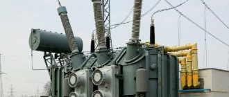
Electricity from a power plant (nuclear power plant, thermal power plant, state district power plant, etc.) is transmitted through overhead line supports many hundreds of kilometers to a substation (I will talk about a 110,000 Volt substation), where step-down transformers are installed - very large and very powerful.
These transformers lower the voltage (in my example to 10,000 Volts) and transmit electricity further, but over a shorter distance - within 10-40 km to the next step-down transformer, which converts the already high voltage of 10 kV into a low three-phase voltage of 400 Volts, which and goes along the wires to our houses.
So, a 110/10 kV transformer installed at a substation is connected to a lot of load - it can be an entire rural area or part of a big city.
The workload changes throughout the day and throughout the seasons and changes greatly.
For example, in winter, many rural residents are heated by electric boilers , so the current consumed is much greater than in summer.
Or there are morning and evening hours of maximum load when people wake up or, on the contrary, come from work, turn on electrical appliances - electricity consumption increases greatly. During the day, the load decreases and sometimes even several times less than in the morning or evening.
Types and technical characteristics of thyristor regulator
Due to the fact that the thyristor passes voltage of only one polarity through itself, it cannot be used to control a transformer without additional elements:
- Connect the thyristor to a diode bridge of 4 diodes at the “+” and “-“ terminals. The “~” pins are connected to the open circuit instead of the switch or in series with it. The diode bridge rectifies the voltage and the thyristor is supplied with power of only one polarity.
- Use two thyristors connected back-to-back and for control the control outputs are connected through a variable resistor. Each element opens at its own polarity, and both together control the voltage across the load.
The opening of the thyristor occurs when a current exceeds a certain value and there are two ways to control the opening angle:
- Variable resistance connected between the anode and the control electrode. During the first half of the half-wave, the voltage and control current increase and when it reaches a certain value, depending on the brand of the element. The disadvantage of this circuit is the limited adjustment range of 110-220V, but this is enough to control the charger transformer.
- Control of pulses that are supplied by a separate circuit to the control electrode at a certain moment of the half-wave of a sine wave. The permissible current and voltage of the thyristor regulator depend primarily on the installed thyristors. The most common are thyristors of the KU 202 series, but in some cases the use of other elements is allowed:
- KU 202N – 400V, 30A. Mounted on M6 thread. When adjusting the primary winding, the current of which is less than 1A, they are used without radiators.
- KU 201l - 300V, 30A, fastening - M6 thread. Can be used in the primary winding.
- KU 201a – 25V, 30A, fastening – M6 thread. Can only be used with radiators when adjusted after the transformer.
- KU 101g – 80V, 1A. Looks like a transistor. They are not used in power circuits of chargers, only in control circuits.
- KU 104a – 6B, 3A. Also not used in power circuits.
Adjusting the welding current on the primary winding
The presence of a welding machine at a construction or production site is explained by simple necessity, since the construction of a modern metal structure, building frame, and the production of parts is almost impossible without the participation of the equipment in question.
In production, in agriculture, on a construction site, and in everyday life, equipment is required for processing metals of various thicknesses, and therefore adjusting the welding current is an important task for any welding machine.
It is advisable to consider the importance of a device better known as a current regulator.
Description of the device
Adjusting the operating current of the machine for making seam joints is an important task that you should definitely be familiar with before starting work. Regulation of the welding current is, first of all, necessary when performing work on processing parts of different thicknesses.
In order to make the adjustment of this parameter of an ordinary welding machine convenient, various methods are used, including switching taps in the primary and secondary windings of the device, quenching the welding current using ballast resistors, etc. However, the most common and reliable method for implementing this possibility is a special current regulator.
Thus, the welding parameter regulator is available for independent repetition and has good indicators regarding the quality of the weld seam and the energy consumption of the device. The regulator has a fairly simple circuit diagram, which will be discussed further.
Device and principle of operation
The operating current regulator for multi-station installations, as well as welding machines, differs from the known ones, which are as follows: the regulating element (regulator) is made in the form of an autonomous device connected to a rectifier through current-limiting reactors and a transformer. It is also connected to a DC source through a rectifier.
The welding current circuit of the device in question includes a reactor with a rectifier. The rectifier is responsible for returning power to the DC network. The operation of the device is ensured by the control unit.
Regarding the principle of operation, it is worth knowing that with a low load resistance, the entire voltage of the supply source is applied to the inverter, while the maximum operating parameter is determined depending on the reactance value of the reactor.
In the considered position in the circuit, which consists of an inverter apparatus, a welding station, and a rectifier, the direct current indicator actually remains identical, the same in all sections.
Only the minimum parameter is consumed from the DC source, determined by the losses in the circuit elements.
As the resistance in the circuit increases, the voltage on the inverter decreases, and the parameter under consideration decreases along with the amount of autonomous power that is removed from the device.
Scheme:
- Inverter;
- Transformer;
- Reactor;
- Rectifier;
- Control block;
- Fast.
As a result of all of the above, changes in the operating current are achieved by changing the inductance in the energy return circuit, which makes it possible to increase efficiency, as well as improve the performance characteristics of such a useful device as a regulator.
How to get a working parameter regulator?
A transformer will be needed with a power reserve of 3 kW. For such a power of a welding transformer, you will need a winding consisting of 200-240 turns of wire in PSD insulation with a cross-section of 5 square millimeters. Regarding the secondary power winding of the welding transformer, it has a cross-section of 16 square meters. millimeters or more.
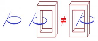
The primary and power windings are separated into different cores. You will need to space the windings for a softer welding process.
When winding the secondary winding and the primary winding on each other, the coupling coefficient is quite high-quality, but at the same time the equipment makes connections quite rigidly.
In such a situation, the solution may be to use a smoothing choke at the output. With the help of a choke, it becomes possible to eliminate voltage dips when crossing zero.
High-quality and correctly wound winding of a welding transformer allows you to obtain reliable parameters of the electric arc and a soft hiss during operation. The voltage of the secondary winding must be selected in the range of 50-55V with a power rating of the welding transformer in the range of 3-3.5 kW. The current indicator can be within the limits of 200-220A.
The current regulator of the transformer apparatus operates on several types of home-made equipment, on the Arc device.
The standard factory adjustment block has been removed, there are additional two windings designed to power the electrical circuit, two thyristors are also inserted and there are power diodes.
The circuit has a choke at the output, and therefore the node in the frame is eliminated. Rework of this kind does not affect the quality side of the welding process.
Electronic version of the device
The main part of the control system of an electronic device of similar action is a control path, including a broadband pulse modulator, welding current and voltage sensors, and a duty cycle controller. The regulator for the argon-arc welding mode provides that the signal from the diesel generator enters PWM.
The preference for PWM in the devices under consideration is due to the fact that in converters with a wideband pulse regulator, the switching frequency of the transistor switch VT, the pulsation frequency of the operating load parameter, remains unchanged throughout the regulation.
Due to this, optimization of the parameters of the inductor and buffer capacitor is achieved, ensuring effective excitation of the arc at the initial stage, maintaining a stable discharge of the electric arc under conditions of low operating current values, and this is quite important when producing seams and joints in the argon-arc processing mode of parts.
In addition to the nodes listed above, the tract also includes input blocks responsible for controlling the charge of the capacitor at the stage of generating a control pulse to the transistor switch by means of a diode bundle with a resistance.
To solve problems of high-frequency energy conversion, a snubber is connected in parallel to the VT switch.
The regulators provide high speed of the path, reliable excitation of the electric arc, combustion stability in various spatial positions, stable transfer of electrode metal during manual welding and in MIG/MAG modes.
The current regulator is an important element of the welding machine. The equipment must be equipped with extremely important components, and therefore information regarding the arrangement of the device for the intended purpose is considered appropriate.
Adjusting the welding current on the primary winding - Metalworker's Handbook
The quality of the weld depends largely on the characteristics of the electric arc. For each thickness of metal, depending on its type, a certain strength of welding current is required.
In addition, the current-voltage characteristic of the welding machine is important; the quality of the electric arc depends on it. Cutting metal also requires its own electric current values. That is, any welding machine must have a regulator that controls the welding power.
What is a triac
The thyristor has a drawback that complicates its use in an alternating current network - it passes through only one half-wave and the output produces a constant pulsating voltage instead of an alternating voltage. Therefore, these devices are used in pairs or together with a diode bridge. The triac is free from this drawback.
A triac is similar in appearance to a thyristor. Just like a thyristor, it opens with a current pulse flowing through the control electrode, but this device passes both half-waves through itself and is capable of operating in an alternating current network.
Schematic diagram of a triac current regulator for active and inductive loads. The design of a triac regulator is similar to a thyristor regulator. The difference is that the triac controls both polarities and therefore there is no need to use a diode bridge or back-to-back connection of elements.
In addition, the polarity of the control voltage does not matter for the triac, which simplifies the pulse control circuit.
Advice! To adjust the triac, you can use a dimmer from an incandescent lamp. To do this, it is connected between the anode and the control electrode of the power triac.
Methods for adjusting welding current - Welding Pros
Adjusting the operating current of the welding machine is of paramount importance for ease of use and the quality of the resulting seam. This is explained by the ability to select the type of electrode used and its thickness in relation to each specific case.
Structurally, the variation of the operating mode can be carried out quite simply (mechanically) or much more complex (thyristor or triac electronic control).
In the latter case, repairing welding equipment when it fails is a difficult task and can only be performed in a special workshop.
Adjustment methods
The following methods are used to correct the current:
- mechanical switching between taps of the windings of the primary and/or secondary circuit (changing the number of working turns);
- their additional shunting with a series-connected active or reactive load;
- distortion (due to the shift-spacing in space of the windings relative to each other) of the connecting magnetic flux or the introduction of an auxiliary shunt choke into it;
- regulation of circuit parameters using an electronic control unit, including the use of pulse width modulation.
The first method, which actually involves manipulating the secondary no-load voltage, does not allow the current to be varied over a wide range, since even for a two- or three-fold change it is necessary to switch additional sections of not only the power winding, but also the primary winding. And this is fraught with complication of the design, excessive consumption of wires, and an increase in the weight of the device and its dimensions.
In the second case, stores of powerful (and, unfortunately, bulky) ballast rheostats with a resistance of tenths and hundredths of an ohm are included in the circuit.
While improving the characteristics of the power transformer and arc parameters, they at the same time dissipate useful power, reducing the overall efficiency of the welding machine.
The third method is somewhat better: unlike the previous ones, it allows you to regulate the current smoothly and not abruptly. Used in transformers of types TS, TSK or TD.
The listed techniques are quite simple and can be used even in homemade designs. And home craftsmen can also repair welding machines of this class.
The situation with the last method under consideration is much more attractive.
Electronic control protects the transformer from overloads and allows you to easily, smoothly and conveniently regulate the welding current, even while the arc is burning.
The elements are not exposed to excessive heat, so they can be mounted in a closed casing. The only drawback is that the arc is slightly more intermittent at minimum power.
News
Electronic current regulator for welding transformer. Transformer current adjustment
TransformerTransformer current adjustment
The quality of the weld depends largely on the characteristics of the electric arc. For each thickness of metal, depending on its type, a certain strength of welding current is required.
In addition, the current-voltage characteristic of the welding machine is important; the quality of the electric arc depends on it. Cutting metal also requires its own electric current values. That is, any welding machine must have a regulator that controls the welding power.
Other simple options for adjusting the voltage in the primary
In addition to thyristor and triac regulators, there are other ways to control the charging current in the primary winding of a transformer:
- Switching the leads of the primary winding. The disadvantage is that these conclusions must be made when winding the coils.
- By connecting the charger after LATRA (laboratory autotransformer). Its power must be at least 160W.
- Variable resistance connected in series with the transformer. Its parameters are approximately 50-100 Ohm, power 50 W and depend on the specific charger.
Despite the advent of modern chargers, many car owners have devices with conventional transformers, and adjusting the device along the primary winding makes it possible to do without powerful thyristors or additional resistances.
Adjusting the welding current on the primary winding - Metalworker's Handbook
The quality of the weld depends largely on the characteristics of the electric arc. For each thickness of metal, depending on its type, a certain strength of welding current is required.
In addition, the current-voltage characteristic of the welding machine is important; the quality of the electric arc depends on it. Cutting metal also requires its own electric current values. That is, any welding machine must have a regulator that controls the welding power.
How to make a current regulator for a welding machine with your own hands
One of the main components of a truly high-quality seam is the correct and precise adjustment of the welding current in accordance with the task at hand.
Experienced welders often have to work with metal of different thicknesses, and sometimes the standard min/max adjustment is not enough for proper work. In such cases, there is a need for multi-stage current regulation, accurate to the nearest ampere.
This problem can be easily solved by connecting an additional device to the circuit - a current regulator.
The current can be adjusted in the secondary (secondary winding) and in the primary (primary winding). Moreover, each method of setting up a transformer for welding has its own characteristics that are important to consider.
In this article we will tell you how to regulate the current in welding machines, provide diagrams of regulators for a semi-automatic welding machine, and help you choose the right welding current regulator for the primary winding for a welding transformer.
Methods for adjusting current
There are many ways to regulate the current, and above we wrote about the secondary and primary windings. In fact, this is a very rough classification, since the adjustment is still divided into several components. We will not be able to analyze all the components within the framework of this article, so we will focus on the most popular ones.
One of the most commonly used current control methods is to add a ballast at the output of the secondary winding. This is a reliable and durable method; you can easily make a ballast with your own hands and use it without additional equipment. Often, ballasts are used solely to reduce current.
In this article, we described in detail the operating principle and features of using a ballast for a semi-automatic welding machine. There you will find detailed instructions on how to make the device at home and how to use it in your work.
Despite many advantages, the method of adjusting the current through the secondary winding when used in conjunction with a welding transformer may not be very convenient, especially for novice welders.
First of all, the ballast is quite bulky and its size can reach a meter in length. The device is also often underfoot and gets very hot, and this is a gross violation of safety regulations.
If you are not ready to put up with these shortcomings, then we recommend that you pay attention to the method when the welding current is adjusted through the primary winding. For these purposes, electronic devices that can be easily made with your own hands are often used. Such a device will easily regulate the current through the primary and will not cause inconvenience to the welder during operation.
The electronic regulator will become an indispensable assistant for a summer resident who is forced to weld under conditions of unstable voltage. Often houses are simply not allowed to use electrical appliances larger than 3-5 kW, and this is very limiting in their work.
Using the regulator, you can configure your device so that it can operate smoothly even with low voltage. Also, such a device will be useful for craftsmen who need to constantly move from place to place while working.
After all, the regulator does not need to be dragged around like a ballast, and it will never cause injury.
Now we will talk about how to make an electronic regulator from thyristors yourself.
Thyristor regulator circuit
Above you can see a diagram of a simple regulator using 2 thyristors with a minimum of non-scarce parts. You can also make a regulator using a triac, but our practice has shown that a thyristor power regulator is more durable and operates more stably. The assembly diagram is very simple and according to it you can quickly assemble the regulator with minimal soldering skills.
The operating principle of this regulator is also simple. We have a primary winding circuit into which the regulator is connected. The regulator consists of transistors VS1 and VS2 (for each half-wave).
The RC circuit determines the moment when the thyristors open, and at the same time the resistance R7 changes.
As a result, we get the opportunity to change the current in the primary of the transformer, after which the current changes in the secondary.