Here you will learn:
- What is and why do you need a water flow switch?
- Design features
- Operating principle
- Device connection diagram
- Installation features
- Self-adjustment procedure
- How to set pressure using a flow switch
- Device selection criteria
- 3 best models of water flow switch for a pump
A water flow switch is a special device installed to protect water pumps from running dry. When water disappears in the system, the protective device is activated and turns off the water supply equipment.
What is and why do you need a water flow switch?
In household water supply systems, the action of a pumping station without water quite often occurs and threatens an accident. This problem is called “dry running”.
As a rule, the liquid cools and lubricates the elements of the system, thereby ensuring its normal operation. Even short-term dry operation leads to deformation of individual parts, overheating and failure of the equipment motor. Negative consequences apply to both surface and deep-well pump models.
Dry running occurs for various reasons:
- incorrect choice of pump capacity;
- unsuccessful installation;
- violation of the integrity of the water pipe;
- low fluid pressure and lack of control over its level, for which a pressure switch is used;
- accumulated debris in the pumping pipe.
An automatic sensor is necessary in order to completely protect the device from the threats posed by a lack of water. It measures, controls and maintains constant water flow parameters.
Pumping equipment equipped with a sensor has many advantages. It lasts longer, breaks down less often, and uses energy more economically. There are also relay models for boilers
The main purpose of the relay is to independently turn off the pumping station when the liquid flow is insufficient and turn it on after normalization of the indicators.
Purpose and benefits
When operating domestic water supply systems, there are often situations when the pump turns on when there is no liquid in the pipes. Such situations, if they occur frequently and continue for a long time, cause overheating of the pump motor and deformation of its parts, which ultimately leads to failure of the entire device. The water pumped by pumping equipment simultaneously performs lubricating and cooling functions, so “dry running,” as it is also called, negatively affects the technical condition of both circulation and submersible pumps.
In order to prevent the occurrence of the described situations, they use a water flow sensor for the pump, operating in automatic mode. Sensors that monitor water flow are successfully used to control the operation of pumping stations serving hot and cold water supply systems, as well as heating systems.
Sensor location diagram in the water supply system
The automatic device in question monitors the parameters of the flow of water that passes through it, and in cases where they differ from the standard ones, it automatically turns on or off the pumping equipment. Working on this principle, the sensor not only protects pumping equipment from “dry running”, but also ensures constant water flow parameters.
Among the advantages of operating pumping equipment on which a fluid flow sensor is installed are:
- reducing energy consumption and, accordingly, reducing the cost of paying for it;
- minimizing the risk of failure of pumping equipment;
- increasing the service life of pumping equipment.
Design features
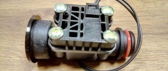
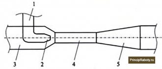
The main tasks that water flow control sensors installed in domestic pipelines solve are to turn off pumping equipment at a time when there is no liquid in the system or its flow pressure exceeds the standard value, and turn it on again when the pressure drops. An effective solution to these important problems is provided by the sensor design, which consists of the following elements:
- a pipe through which water enters the sensor;
- a membrane that makes up one of the walls of the inner chamber of the sensor;
- a reed switch that provides closing and opening of the pump power supply circuit;
- two springs of different diameters (the degree of their compression regulates the pressure of the fluid flow, at which the water flow switch for the pump will operate).
Main components of an industrial flow sensor
The device of the above-described design works as follows:
- Entering the inner chamber of the sensor, the water flow puts pressure on the membrane, displacing it.
- The magnetic element fixed on the back side of the membrane, when it is displaced, approaches the reed switch, which leads to the closure of its contacts and the pump being turned on.
- If the pressure of the water flow passing through the sensor drops, the membrane returns to its original position, the magnet moves away from the switch, its contacts open, and accordingly, the pumping unit is turned off.
The operating principle of a flow sensor based on a permanent magnet and a reed switch
Sensors that monitor water flow are installed quite simply in pipeline systems for various purposes. The main thing is to choose the right device, paying attention to its operating parameters and characteristics of the pumping equipment.
Main characteristics
When choosing water flow sensors to equip a pipeline system, the following parameters must be taken into account:
- material for manufacturing the body and internal elements;
- operating pressure for which the sensor is designed;
- temperature range of the liquid to control the flow of which the device will be used;
- protection class and requirements for operating conditions;
- diameter of mounting holes and thread parameters in them.
Each of the above parameters affects the operational features of water flow sensors, so it is worth considering them in more detail.
The reliability of such a device, its ability to withstand loads arising during operation, as well as its durability depend on the material from which the sensor body and its internal parts are made. When choosing a fluid flow sensor, it is better to give preference to models for the manufacture of which various metals were used - stainless steel, brass or aluminum. During operation, both the body of the flow sensor and its internal elements experience significant pressure from the liquid passing through it. Only durable materials can withstand such a load for a long time. In addition, phenomena such as water hammer are common in pipelines, the consequences of which can quickly damage the sensor if inappropriate materials were used for its manufacture.
Flow sensor with brass body
The operating pressure at which the fluid flow sensor can operate correlates with the power of the pump used, so special attention should be paid to this parameter. In addition, this parameter also determines what characteristics the liquid flow transported through the pipeline will have. Those models of water flow sensors, which are designed with two springs, can control the operation of the pump at the lower and upper pressure levels. It is better to give preference to devices of this particular type.
The temperature of the liquid for which the sensor is designed has a direct impact on the systems in which it can be used. Naturally, when choosing such a sensor to equip a heating or hot water supply system, you should pay attention only to those models that can work with water heated to a high temperature. For pipelines through which cold water is transported, flow sensors are used, designed to work with liquids having a temperature of 60–80°.
Boost pump with flow sensor
The level of humidity and ambient temperature at which the fluid flow sensor can be operated are also important parameters. The protection class of such a device indicates what loads it can withstand when working in tandem with pumping equipment.
Sensors that monitor water flow are usually chosen for ready-made pipeline systems or for those whose design has already been developed. That is why you should pay attention to the dimensions of the mounting holes: they must fully correspond to the dimensions of the pipeline elements on which the sensor is planned to be installed.
Operating principle
There are several types of water flow switches and similar safety devices, each of which is equipped with different automation that turns the pump on and off in response to certain indicators.
Most common triggers:
- Liquid level (water level switch);
- Liquid pressure level at the outlet pipe (press control);
- Presence of water flow (flow switch);
- Temperature of the working environment (thermal relay.
Let's look at each of these devices in more detail.
Classic relay
A classic example of a relay that controls the flow of liquid
Such a device consists of two main structural elements: a reed switch and a petal (valve) on which a magnet is mounted. The reed switch, which acts as a contact that responds to changes in the position of the magnet, is located outside the water flow and is reliably insulated.
On the opposite part of the structure there is a second magnet, which creates a reverse force, which is necessary to return the petal to its original position at the moment the fluid flow weakens.
When the pump is filled with water, it acts on the petal, causing it to rotate around its axis. The movement of the petal brings the magnet closer to the reed microswitch, which is activated by the resulting magnetic field.
The reed switch connects the contacts of the pump and the electrical network, as a result of which the device is turned on. As soon as the flow of liquid has stopped, the petal, which no longer receives additional pressure, returns to its original position under the influence of the force of an additional magnet and the contacts open.
Advantages of the petal flow switch:
- Does not reduce water supply pressure;
- Works instantly;
- No delay between retriggers;
- Using the most accurate circulation trigger to turn on the pump;
- Simplicity and unpretentiousness of design.
There are also flow switches, the valve design of which is made without return magnets, where the second magnet is replaced by conventional springs. However, such relays in practice show less stability, since they are overly susceptible to the influence of small pressure surges in the water flow.
Press control
Press control relay for water flow
Press control gives a command to turn on the pump only when the water pressure level in it rises to a certain level (this indicator is adjustable, most often it ranges from 1 to 2 Bar), the pump is turned off due to opening of the contacts within 5-10 seconds after completely stopping the flow of water pumped out of the well.
Such devices can be used either in conjunction with a hydraulic accumulator, performing the function of controlling a pumping station, or installed directly on the outlet pipe of the pump, protecting it from idling.
Press control, in comparison with a conventional relay that responds to changes in the level of water flow, has one significant drawback - if it is installed on a surface-type pump, then each time before turning it on you must fill the unit with water yourself. The problem can be solved by installing additional check valves, but this is far from a panacea.
Thermal relay
Among all the above types of safety devices, the thermal relay has the most complex design. The technology of its operation is based on the thermodynamic principle, according to which the thermal difference between the temperature of the water flow in the pump and the temperature to which the relay sensors are set is compared.
When the thermal relay is connected to the pump, which is located inside the well, a certain amount of electricity is constantly supplied to it, which is spent on heating the sensors to a temperature several degrees higher than the temperature of the measured liquid.
In the presence of water flow, the sensors are cooled, which is fixed by a microswitch. The thermal change is a signal after which the connection between the pump contacts and the electrical network is made. As soon as the flow of water from the well stops, the microswitch disconnects the contacts and the pump turns off.
Thermal relay that responds to temperature changes
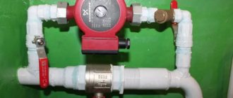
In addition to downhole units, a thermal flow relay is an ideal option for dry-running protection for a circulation pump.
The thermal relay allows you not only to increase the useful life of the circulation device, but also to save a considerable amount of electricity, since the thermal relay automatically turns off the pump when pressurizing the water flow in the heating line is not required.
When the heater is turned off and the water in the system is cold, the circulation pump is not needed, and the thermal relay keeps the contacts closed. When you turn on the boiler, as the water in the pipes reaches the set temperature, the thermal relay turns on the circulator, and it begins to build up pressure to the required level.
It is worth noting that most leading manufacturers of circulation pumps independently install thermal flow switches on their devices. This is mainly typical for premium class pumps. This is due to their high cost and complexity of design.
Level relay
The simplest and most utilitarian version of a safety device for a water pump is a water level switch, commonly known as a float switch.
The “float,” which must be mounted inside the source 20-25 centimeters above the level of the pump, monitors the amount of water in the source, and as soon as the water drops below the float sensor, the pump automatically turns off.
The relay itself is connected to the phase that is supplied to power the pump. The float sensor is adjusted by changing the length of the adjusting cable. Higher-quality floats can be customized with additional functions, but this already applies to expensive models of equipment, which are quite rare in domestic use.
A float switch is a proven means of protection for any well and drainage devices, but a water level switch cannot be used in deep wells, since there are serious difficulties with its precise adjustment.
Submersible Drain Pump with Float Switch
Also, floats do not always work well in cramped conditions, when the difference between the diameter of the well and the pump is only a few tens of millimeters. In this case, there is simply no point in using it, since the operation of the float will become too unstable.
Float switches are used both on conventional well pumps and on drainage samples. Moreover, there they are even more in demand, because unlike standard wells, the working environment of a drainage pump tends to constantly decrease. Dry running of drainage models is no less harmful than borehole or well pumps.
Design and operating principle
The sensor has a unique device, thanks to which it performs its direct functions. The most common modification is the paddle relay.
The classic building scheme includes the following important elements:
- an inlet pipe that passes water through the device;
- valve (petal) located on the wall of the inner chamber;
- an isolated reed switch that opens and closes the power supply circuit;
- springs of a certain diameter with varying degrees of compression.
While the chamber is filled with liquid, the force of the flow begins to act on the valve, moving it around its axis.
A magnet built into the back of the petal comes close to the reed switch. As a result, the contacts close, turning on the pump.
The flow of water is understood as the speed of its physical movement sufficient to turn on the relay. Reducing the speed to zero, resulting in a complete stop, returns the switch to its original position. When setting the response threshold, this parameter is set taking into account the conditions of use of the device
When the flow of fluid stops and the pressure in the system drops below normal, the compression of the spring weakens, returning the valve to its original position. Moving away, the magnetic element ceases to operate, the contacts open and the pumping station stops.
Some modifications are equipped with a return magnet instead of springs. Judging by user reviews, they are less susceptible to minor pressure surges in the system.
Petal relays have a large number of advantages. Among them are a simple and unpretentious design, instant response, no delays between repeated responses, and the use of a precise trigger to start the equipment.
Depending on the design solution, several more types of relays are distinguished. These include rotary devices equipped with a paddle wheel rotating in a water flow. The speed of rotation of the blade in them is controlled by touch sensors. If there is liquid in the pipe, the mechanism deflects, closing the contacts.
There is also a thermal relay that operates according to thermodynamic principles. The device compares the temperature set on the sensors with the temperature of the working medium in the system.
If there is flow, a thermal change is detected, after which the electrical contacts are connected to the pump. If there is no water movement, the microswitch disconnects the contacts. Thermal relay models are characterized by high sensitivity, but they are quite expensive.
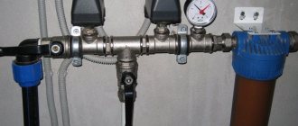
Device connection diagram
The operating efficiency of the relay greatly depends on its correct installation. It must be remembered that the device can only be installed on those sections of the pipeline that are located horizontally. In this case, you will need to ensure that the sensor membrane is in a vertical position. The correct relay connection diagram looks like this:
During installation, the sensor must be connected to the drain part of the pipe using a threaded connection. The distance at which the relay should be located from the pipe should be more than 5.5 cm.
There is an arrow on the body of the device indicating the direction of liquid circulation. When installing the device, you need to make sure that this arrow coincides with the direction of water flow in the system. If dirty water is used for domestic purposes, then cleaning filters should be installed in front of the sensor.
Areas of use
In domestic conditions, water flow sensors have found their use mainly in devices that require constant monitoring of the life support systems of the house and compliance with a certain mode of their operation. By controlling the water supply, motion sensors can significantly reduce the cost of maintaining a home and make life much more comfortable and safer.
For gas boiler
The main place for using water flow sensors in modern homes are gas boilers. Modern gas boilers equipped with such sensors combine the functions of a water heater and a heating boiler.
The water flow sensor installed on the tap water supply pipeline reacts to the start of water movement when the hot water tap is opened.
The sensor sends a signal to the boiler control board, and the electronics turns off the heating circulation pump, extinguishes the gas heating nozzles, and closes the water circulation valve in the heating system. And then the board turns on the nozzles for heating running water and the process of heating water begins in the heat exchanger. When the tap is closed, the sensor detects that the water movement has stopped, which is signaled to the control board.
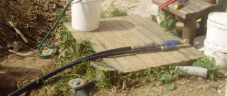
For pump
Many modern households are equipped with autonomous water supply systems. Such systems allow you to have a level of comfort in a private house comparable to apartments, but at the same time not depend on a centralized water supply.
The system, consisting of a pump, a water tank and a control system, allows you to service all the systems necessary for comfortable living - automatic washing machines, dishwashers, hot water and a toilet.
The role of the water flow sensor is that when any of the devices connected to the water supply system is turned on or water selection begins, the sensor turns on the pump and the water supply automatically starts. It doesn’t matter whether the laundry starts, the kitchen faucet opens, or the toilet cistern flushes.
Another option for using water flow sensors is automatic irrigation systems. Here, in addition to the opening function, the flow sensor controls the amount of water used for irrigation. This function is necessary to control dosed watering and avoid waterlogging of the soil. A sensor installed on the central pipeline supplies information to the system control panel.
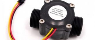
Today, two types of water flow sensors are most widely used: a Hall sensor and a reed switch relay.
A flowing water sensor, based on the operating principle of a Hall sensor (also called a flow meter), is a small turbine on which a magnet is mounted. When the turbine rotates, the magnet creates a magnetic field and, like a turbine in a hydroelectric power station, generates small electrical impulses that are sent to the boiler control board. The turbine rotation speed depends on the water supply speed; the higher the flow, the clearer the pulses. Thus, thanks to the Hall sensor, it is possible not only to signal the flow of water, but also the speed of water supply.
The reed water flow sensor is a sensor based on the principles of a magnet. Fundamentally, this sensor looks like this - inside a chamber made of composite material there is a magnetic float; when water pressure increases, the float moves around the chamber and affects the reed switch.
The reed switch, which is nothing more than two magnetic plates in a chamber without air, opens under the influence of the magnetic field of the float, and the control board switches the boiler to hot water supply mode.
Reed water level sensor:
Water flow meter:
Installation features
Paddle switches are mounted either at the pump inlet or at the valve inlet. Their task is to record the initial entry of liquid into the working chamber, and therefore contact with it must be detected first of all on the relay itself.
Pressure control units are installed only with the help of specialists, as they require adjustment. They are installed in the same way as the petals, by connecting the inlet to the pumping device. However, unlike conventional petals, pressure switches are almost always used in conjunction with pumping stations.
Thermal relays are rarely used separately, since the thing is too expensive. It will most likely be connected at the assembly stage of the pump itself. However, a good master will certainly be able to cope with the installation of this device. The complexity of the installation lies in the need to mount several sensitive thermal sensors, and then bring them together.
Liquid level switches or floats rarely require separate installation. They are either already connected to the pump or require a schematic connection using terminals. Which takes very little time. And even a child can cope with this work.
Ultrasonic water flow sensors
Ultrasonic water flow sensors operate on the principle of measuring the signal travel time and the interaction of ultrasonic vibrations with the measured medium. Ultrasonic sensors quickly and accurately measure liquid flow, have high measurement accuracy, and compensate for environmental conditions (steam, temperature, etc.).
We only offer direct supplies of instrumentation from the Dwyer factory. The list and description of products fully corresponds to the printed catalog and the original website of the manufacturer. Share a link to these devices with your colleagues, click on the social network button:
Self-adjustment procedure
For adjustment, the sensor has special bolts. By loosening or tightening them, you can reduce or increase the compression force of the spring.
This sets the pressure level at which the device will operate.
Almost always, manufacturing companies produce equipment with adjusted settings. Despite this, sometimes additional self-adjustment is required
In most cases, setting up automatic equipment is not difficult.
It is advisable to adhere to the following algorithm:
- drain the liquid from the system until the pressure mark reaches zero;
- turn on the pumping unit and slowly let the water back in;
- record the flow pressure indicator when the pump is turned off with a sensor;
- start draining again and remember the indicators at which the pumping equipment will start working;
- open the relay and use the adjusting bolt to set the minimum level of compression of the larger spring required to activate the device and start the pump (more compression increases the degree of pressure, less - reduces it);
- in a similar way, adjust the compression force of a smaller spring mechanism, setting the limits of the maximum pressure, upon reaching which the relay measuring the water flow will turn off the pump.
Having completed all the described manipulations, you should make sure that the adjustments made are correct. To do this, the pipeline is filled with liquid and then drained, assessing the sensor’s response when the set values are reached.
If the test result is unsatisfactory, the procedure is repeated.
Having insufficient experience and qualifications, it is better to seek help in adjustment from specialists. They will analyze the specific situation, take into account the technical characteristics of the equipment and select the most correct pressure level values
To ensure that the pipeline through which the liquid passes works properly and stably, regular annual checks of the flow sensors are carried out. If necessary, the operating parameters are adjusted.
Sensor types
Today, the most popular and advanced water flow devices are reed switch relays and Hall sensors.
Description:
- A flow meter or Hall sensor is a small turbine with a magnet. As soon as the turbine begins to rotate, the magnet creates a field and generates electrical pulses that are transmitted to the boiler board (for example, Ferroli).
- The reed switch regulator also uses magnetism. A float magnet is installed inside the chamber. As soon as the water pressure increases, the float moves and begins to act on the reed switch (several magnetic plates that move apart under the influence of the float).
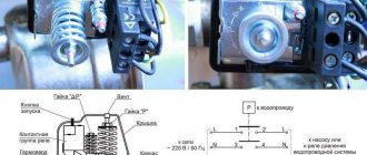
How to set pressure using a flow switch
Briefly - for 5 seconds. – press button “1”:
In this case, the “accident” lamp should blink red. This is where we entered programming mode. Now we turn on the pump, and as it works, it builds up pressure. It is clear that all taps in the house must be closed. We look at the pressure on the pressure gauge. For example, we need the water supply to be 2 atm, so we wait for the pump to build up this pressure. As the arrow on the pressure gauge shows the required pressure, press button “1” again. The pump will turn off.
We press the “2” button, thereby “driving” into the relay’s memory that at this pressure the pump should turn off.
Now we are programming the lower limit. To do this, open any tap so that the pressure begins to drop. When the pressure gauge shows the lower pressure we need, press button “1” again and the pump will turn on. By pressing button “2” we “drive” the relay into the head so that at this pressure the pump must be turned on.
Then all these options are saved, and the pump will turn on and off in accordance with them. The device is very comfortable, perfectly protects the pump from failure, buy it - you won’t regret it (if you really need it).
Flow sensor malfunctions
Design and principle of operation of a rotary pump
Common malfunctions that may occur during operation:
- The DHW mode does not start, the equipment is unstable. To make sure that it is the regulator that has failed, you need to take a multimeter and measure the resistance. If it is approximately 2.5 kOhm, then according to the table this indicator should be achieved when heated to 60 degrees. But if the device is cold, then the problem is definitely in the water flow sensor. The regulator will “say” that the water is already heated and additional temperature is not needed. To fix the problem, you will have to completely replace the failed sensor. But we must not forget that it has direct contact with water and before removal it is necessary to drain all the water from the boiler (Baksi or other companies) and shut off its supply.
- If error No. 201 appears on the indicator, this means that there is a break or damage to the wires that are connected to the regulator. For the regulator to work normally, you need to restore its original position.
- Error No. 202 - short circuit. In this case, you need to check the device itself or the wires that are connected to it.
Device selection criteria
When choosing equipment that controls the force of water flow, you should carefully study its technical characteristics.
Particular attention should be paid to the operating temperature and pressure range for which it is designed, the diameter of the threads and mounting holes, the protection class, and application nuances. It is also important to clarify what materials the product is made from.
Experts consider devices made of brass, stainless steel, and aluminum to be the most reliable and durable. These materials protect the structure from the critical consequences of a common phenomenon in water supply systems - water hammer.
When considering different modifications of the relay, it makes sense to purchase a version made of metal. The housing and working components of such devices are highly durable.
This fact allows the equipment to withstand serious loads for a long time that arise due to significant pressure in the water supply from the liquid passing through the sensor.
The pressure value at which the relay operates must correspond to the power of the installed pump. The parameters of the water flow circulating through the pipeline depend on this characteristic.
It is advisable to choose a device with two springs that controls the operation of the pumping station according to certain lower and upper pressure marks.
The operating temperature range of the sensor directly indicates its possible area of application. For example, models with a high limit temperature are designed for hot water supply circuits and heating systems. For cold water pipelines, a range of up to 60 degrees is sufficient
Another important criterion that deserves special mention is the climatic conditions necessary for the operation of the product. This refers to the recommended air temperature and humidity level that the device needs to provide in order for it to perform at its best.
The maximum permissible load for a particular device is determined by the protection class specified in the technical specifications.
When purchasing a flow sensor, you should check the thread diameter and the dimensions of the mounting holes in the equipment: they must fit perfectly with the pipeline elements. The correctness and accuracy of further installation, as well as the efficiency of the relay after installation, depend on this.
Trusted Instruments
Among the entire range of relays, the two models that are in approximately the same price category are in greatest demand - about $30. Let's take a closer look at their characteristics.
Genyo Lowara Genyo 8A
Development of a Polish company engaged in the production of electronic equipment for control systems. Designed for use in domestic water supply systems.
Genyo allows automatic pump control: starting and shutting down based on actual water consumption, preventing any pressure fluctuations during operation. Also, the electric pump is protected from running “dry”
The main purpose is to control the pump and control the pressure in the pipes during operation. This sensor starts the pump when the water flow exceeds 1.6 liters per minute. It consumes 2.4 kW of electricity. Operating temperature range – from 5 to 60 degrees.
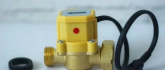
Grundfos UPA 120
Manufactured in factories in Romania and China. Maintains stable water supply in premises equipped with individual water supply systems. Prevents pumping units from idling.
The Grundfos brand relay is equipped with a high protection class, allowing it to withstand almost any load. Its electricity consumption is about 2.2 kW
The device’s automation starts at a liquid flow rate of 1.5 liters in one minute. The limit parameter of the temperature range covered is 60 degrees. The unit is manufactured in compact linear dimensions, which greatly facilitates the installation process.
Installation of a relay on a pump or station
If installation of the device is required, the work can be done independently, especially if you have to be away and there is no way to constantly monitor the operation of the pumping equipment.
When you do not need to install a relay:
- if water is pumped from a well with a large volume, that is, liquid reserves are not limited, and the pump power is minimal;
- It is possible to turn off the installation when the water level drops.
Equipment installation rules:
It is important to monitor the membrane - the part must take a vertical position. Installation is carried out to the drain pipeline section using threaded couplings. There is a special slot for this. Before starting work, the threads are sealed with linen or other plumbing thread
Winding the thread towards the end clockwise will increase the reliability of fastening and fixation. Factory sensors are equipped with an arrow drawn on the body - this is the direction of flow, which must match during installation. When installing relays in water supply pipelines with dirt particles, cleaning filters are first installed. It is better to mount them next to the sensor to extend the service life of the device.
Testing of the installed device is carried out with connection to the power supply:
- the free ends of the contacts are connected to the wire core;
- grounding is mounted to the screw;
- the device is connected by connecting the device with a wire (watch the color of the corresponding wires);
- system functionality is checked.
Self-adjustment of the water movement sensor
The factory device is equipped with bolts, by tightening or loosening which you can increase/decrease the spring compression. Bolts will be required if you need to install the sensor at a certain pressure level at which the mechanism is triggered.
Algorithm of actions:
- drain the liquid from the system;
- wait until the pressure mark reaches zero;
- start the pumping unit;
- run the water back in the slowest mode;
- remember the flow pressure indicator when the pump relay is turned off;
- drain the liquid again, recording the indicators when the system starts operating.
Now you need to open the relay, use the bolt to adjust the compression level of the larger spring - this will trigger the device when the pump starts. The adjustment is made taking into account that strong compression will increase the degree of pressure, and weak compression will decrease it. Then the compression force of the smaller spring is adjusted - here the limit of the maximum pressure level is set, upon reaching which the relay will automatically turn off the pump.
As soon as the adjustment is completed, start the system, evaluate the results of the work when filling the pipeline and draining the flow. If adjustment changes are necessary, repeat the procedure. Checking functionality and adjusting operating parameters is an annual procedure that extends the life of the device.
Connecting and adjusting the sensor
The efficiency of the sensor that monitors the flow of water and controls the operation of pumping equipment largely depends on the correct installation of this device. It should be borne in mind that such a sensor, regardless of the type and purpose of the pipeline, can only be installed in horizontal sections. In this case, it is necessary to ensure that the sensor membrane is located strictly in a vertical position.
When installing a liquid flow sensor, it is connected to the drain part of the pipeline using a threaded coupling. In this case, the distance at which such a device should be located from the pipe itself cannot be less than 55 mm.
Flow sensor installation diagram
On the housing of factory water flow sensors there is always an arrow that indicates in which direction the liquid should move through them. When installing the sensor on the pipeline, you must ensure that this arrow coincides with the direction of water movement. If the sensor is installed in a system through which heavily contaminated liquid is transported, filters must be placed in front of it for the correct operation of such a device.
Electrical connection diagram
Despite the fact that fluid flow sensors are supplied from manufacturing plants with already adjusted parameters, independent adjustment must be performed periodically. For this purpose, special bolts are provided in the design of the sensors. With the help of the latter, the degree of compression of the springs is increased or decreased, setting the level of pressure at which this device will operate.
Leaf type flow sensor adjustment controls
So, to adjust the water flow sensor with your own hands, you need to perform the following steps:
- drain the water from the pipeline system and make sure that the pressure has reached zero;
- turn on the pump and start filling the system with water;
- when the pump is turned off, which occurs due to a signal from the sensor, record the value of the liquid pressure;
- Draining the liquid from the system again, record the pressure value of its flow at which the pump will turn on;
- by removing the sensor cover and using a special bolt, adjust the degree of compression of the large-diameter spring (this way you will set the minimum pressure level at which the device will operate and the pump will turn on; it should be borne in mind that compression of such a spring increases the pressure level, and weakening reduces it);
- Having filled the system again with water and starting to drain it, check whether the sensor is adjusted correctly and whether it turns off the pump at the required pressure level (if the device is adjusted incorrectly, the entire procedure described above should be repeated);
- by changing the degree of compression of a spring of small diameter, set the maximum pressure level at which the pump will turn off (the difference between the sensor response thresholds increases when such a spring is compressed and decreases when it is weakened);
- after adjusting the degree of compression of a small-diameter spring, check that this procedure is performed correctly by starting to fill the system with water and recording the pressure value at which the pump turns off (if this adjustment is performed incorrectly, it should also be repeated until the desired result is achieved).
Rotary relays and flow type sensors
Rotary sensors are mainly used to measure and control fluid flow. Structurally, they are made in the form of a paddle wheel rotating in a fluid flow; its rotation speed is recorded by sensors. The electronic circuit allows for analog, frequency or discrete control of the operation of the equipment.
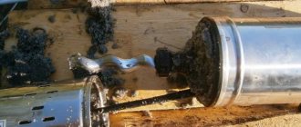
Piston devices
The piston is placed in the valve seat and, under the influence of water pressure, moves in the vertical direction to a height proportional to the force of the flow. A permanent magnet mounted on the piston approaches the reed switch and the contacts in it close. Piston devices can be installed on horizontal and vertical pipelines thanks to the built-in return spring, which returns the piston to its original position in the absence of flow.
appearance