Even novice welders know that during welding work various components are used, such as wire or electrodes. And if to operate a welding machine you only need access to electricity and can work endlessly, then components tend to run out. To ensure that materials do not run out at the most inopportune moment, their quantity can be pre-calculated. This is especially useful during repairs, since it is possible to calculate the cost of welding work and tell the customer the exact price.
In this article we will explain in detail how to calculate the wire, give an example of the calculation and tell you about all the features.
Electrode consumption during welding
The main consumable material for welding work is consumable electrodes. Before starting work, you need to calculate the required number of electrodes (at least approximately). Consumption depends on several factors:
- brand of electrode or wire;
- seam sections;
- type of welding.
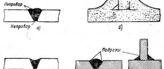
Depending on the type of connection (butt, corner, T), the cross-sectional area of the seam is calculated differently. Below are examples of formulas, where b corresponds to the distance between the edges of the parts, S to the thickness of the part, and e and g to the width and height of the seam.
Electrode consumption rates for welding
The official documents VSN 452-84 or VSN 416-81 (“Departmental Construction Standards”) indicate production standards for 1 joint and 1 meter of seam. The indicators are calculated separately for different types of welding:
- manual arc (MMA);
- manual argon arc (TIG);
- automatic submerged arc welding, etc.
Example of standards for welding joint type C8:
Consumption of electrodes per 1 meter of welding seam
The consumption of electrodes can be determined independently. It consists of the mass of deposited metal and losses (these include spattering, slag formation, cinders). First, let's calculate the mass of deposited metal using the formula:
Mass = weld cross-sectional area * metal density * weld length
Density values are easy to find out from reference literature (density of carbon steel - 7.85 g/cm3, nickel-chrome steel - 8.5 g/cm3). Then, using the second formula, we calculate the total consumption of electrodes during welding:
Consumption rate = mass of deposited metal * consumption coefficient
The consumption coefficient depends on the specific brand of electrode. These data are provided in regulatory documents such as VSN 452-84 (see next section). To calculate the consumption in kilograms per linear meter (kg/m), you need to take the length of the seam in the first formula as 1 meter.
How to calculate consumption
The consumption of welding materials for argon-arc welding or the consumption of wire for semi-automatic welding per meter of seam is made according to the following formula:
N = G*K
Where “N” is the desired parameter or, in other words, the rate of wire consumption per 1 meter, which we need to calculate. “G” is the mass of deposit on the finished weld, again one meter long. And “K” is the correction factor, which depends on the mass of the deposited material to the metal consumption required for welding. To find out the value of G (weight of deposit on a welded joint), we need this formula:
G = F*y*L
The letter "F" indicates the cross-sectional area of the joint in square meters. The letter “y” is the density of the metal from which the wire is made.
Note! "y" value is extremely important because each brand of wire can vary significantly in weight due to the metal used to make it.
The value “L” is automatically replaced by the number 1, since we are calculating exactly 1 meter. If you need to calculate more or less than a meter, then use a different figure. Using these formulas, you can calculate the wire consumption during bottom welding. For other welding methods, you need to multiply “N” “K” , other than 1.
"K" value changes according to the position:
- In the lower position, “K” is equal to the number 1
- With semi-vertical - 1.05
- When vertical - 1.1
- With ceiling - 1.2
If you are welding metal using a semi-automatic machine, consider the shielding gas used in the work, the characteristics of your welding machine, the diameter of the wire and the features of the parts.
Thanks to these simple calculations, you can easily find out the amount of wire needed to weld parts when using argon arc welding or any other type of welding work. Take into account all the features of the type of welding and the wire used so that the calculations are accurate.
Electrode consumption coefficients
| Coefficient | Electrode brands |
| 1,5 | ANO-1, OZL-E6; OZL-5; TsT-28; OZL-25B |
| 1,6 | ANO-5, ANO-13, TsL-17, OZL-2, OZL-3, OZL-6, OZL-7, OZL-8, OZL-21, ZIO-8, UONI-13/55U |
| 1,7 | OZL-9A, GS-1, TsT-15, TsL-9, TsL-11, UONI-13/NZH, UONI-13/45 |
| 1,8 | OZS-11, OZL-22, OZL-20, NZh-13, VSC-4, K-5A |
| 1,9 | ANZHR-2, OZL-28, OZL-27 |
STANDARDING OF WELDING MATERIALS FOR ARC WELDING
Transcript
1 Department of Vocational Education of the Tomsk Region Regional state budgetary vocational educational institution Tomsk Industrial Humanitarian College RATING OF WELDING MATERIALS FOR ARC WELDING REFERENCE MANUAL Specialty Welding production PM.04 Organization and planning of welding production Developed by Volkov V.V. teacher Tomsk
2 Considered at a meeting of the Central Committee for Electrical Engineering and Welding Production Minutes 2022. Chairman of the Central Committee V.V. Volkov Approved and recommended for use by the College Methodological Council 2022. Deputy Director for UMR G.I. Rudenskaya Rating of welding materials for arc welding: a reference manual Compiled by: Volkov V.V., teacher of OGBPOU Tomsk Industrial and Humanitarian College Editor: Kurbanova O.M., methodologist of OGBPOU Tomsk Industrial and Humanitarian College Reviewer: Shishko Yu.A., teacher specialty Welding production, Tomsk College of Railway Transport branch of the Federal State Budgetary Educational Institution of Higher Professional Education Siberian State University of Transport. The reference manual is compiled in accordance with the requirements of the Federal State Educational Standard of the specialty Welding production for theoretical development and practical development of the topic Standardization of welding work of the professional module PM.04 Organization and planning of welding production. Contains algorithms for technological calculations based on standards for technological modes of manual, partially mechanized and automatic fusion arc welding: coated electrodes and welding wire, welding fluxes and shielding gases. The structural elements of welded edges and welded seams of joints widely used in modern industry are given. The cost of welding materials is indicated. Contains illustrative material. This manual can be used when mastering basic professional educational programs of secondary vocational education in the field of training Metallurgy, mechanical engineering and materials processing, when mastering basic professional educational programs of secondary vocational education in the profession of Welder (manual and partially mechanized welding (surfacing), Tomsk, Michurina St., 4 2 tel. (fax): (382-2)
3 Contents page 1 Calculation of consumption rates of welding materials for arc welding Calculation of consumption rates of coated electrodes and welding wire 4 for arc welding 1.2 Consumption rate of coated electrodes and welding wire Calculation of consumption rates of welding fluxes for arc welding Calculation of consumption rates of shielding gases for arc welding 8 2 Standards for technological calculations for arc welding Structural elements of the welded edges and weld seam during manual arc welding with a consumable coated electrode. Cross-sectional area of the deposited weld metal and the calculated mass of the deposited metal of welded joints according to GOST Structural elements of the welded edges and weld in partially mechanized fusion welding. Cross-sectional area of the deposited weld metal and the calculated mass of the deposited metal of welded joints according to GOST Structural elements of the welded edges and weld in automatic fusion welding. Cross-sectional area of the deposited weld metal and the calculated mass of the deposited metal of welded joints according to GOST Cost of welding materials 42 List of sources used 43 3
4 1 Calculation of the consumption rates of welding materials for arc welding 1.1 Calculation of the consumption rates of coated electrodes and welding wire for arc welding The consumption rate N e (kg) of coated electrodes and welding wire for the manufacture of a welded structure is determined based on the length of the welds L w (m) and specific rate of consumption of electrodes G e per 1 m of a weld of a given standard size. The consumption rate N e (kg) is determined by formula 1: N e = G e * L w (1) The specific consumption rate G e (kg/m) is generally calculated using formula 2: G e = kp * m n (2 ), where kp is the consumption coefficient, taking into account the inevitable losses of coated electrodes and welding wire; m n—calculated mass of deposited metal, kg/m. The mass of the deposited metal m n (kg/m) is calculated using formula 3: m n = ρ * F n (3), where ρ is the specific density of the deposited metal, kg/m 3, ρ = 7850 kg/m 3 (for carbon steels); F n - cross-sectional area of the deposited weld metal. The values of m n and F n for welded joints widely used in industry are given in the section Standards for technological calculations for arc welding for manual, partially mechanized and automatic fusion arc welding. Also in this section there are formulas for calculating F and specific thicknesses established by regulatory documentation. 4
5 For electric arc welding, the required dimensions of structural elements of welded edges and welded seams are taken from GOST, GOST, GOST standards. For electric arc welding of steel pipelines, the required dimensions of structural elements of welded edges and welded seams are taken from GOST. The specific consumption rate of coated electrodes and welding wire during arc welding should be increased when welding vertical or horizontal seams by 5%, when welding ceiling seams by 10%, when welding intermittent seams by 15%. 1.2 Consumption coefficient of coated electrodes and welding wire In manual arc welding, the consumption coefficient kp, which takes into account the inevitable losses of coated electrodes, is determined for each specific brand of electrode according to Table 1. Table 1 Consumption coefficients of electrodes for welding steels k p Group Coefficient Brands of electrodes consumption electrodes k p LB-52A "Garant"; VSF-65U; VSF-75U; VSF-85; I 1.4 OZSh-1; WCC-4A; OZL-25B II 1.5 III 1.6 IV 1.7 UONI-13/45; ANO-11; TMU-21U; OZS-18; OZS-6; OZS-17N; WCC-4; WCC-60; TML-1U; TML-3U; UT-28; OZL-5; OZL-29; OZL-25; OZL-36; ANV-20; Pipeliner6P+; FoxTsel OZL-8; OZL-7; OZL-14A; OZL-3; OZL-21, OZL-23; VN-48; UONI-13/55K; TsU-5; DSK-50; OZS-25; SK2-50; UONI-13/55U; ANP-2; UONI-13/85; ANO-5; OZS-23; ANO-4; ANO-14; OZS-4; OZS-22N; OZS-22R; TML-4B; TsL-39; SMV-96; SMA-96; OZL-6; OZL-2; ANZHR-2, LB-52U; UONI-13/65 OZL-37-1; SM-11; OZS-24; ANO-6; ANO-18; OZS- 12; OZS-21; OMA-2; OZL-9A; GS-1; ANZHR-1; ANZHR-ZU; OZL-19; NII-48G; UONI-13/NZh; TsL-11; TsT-15; TsL-9; OZL-17U, UONI-13/55; MP-3; MR-3S; OK-46.00; OK-53.70; OK
6 Electrode consumption coefficients kp, indicated in Table 1, were determined experimentally for the following brands of electrodes: Pipeliner 6P+, FoxTsel, LB-52U, LEZ UONI-13/65, LEZ UONI-13/55, MR-3, LEZ MR- 3C, OK-46.00, OK-53.70; OK The consumption coefficient kp, which takes into account the inevitable losses of coated electrodes, is determined for electrodes with a length of 450 mm. When using electrodes of a different length, it is necessary to use the correction factor k p in technological calculations, which is 1.02 for an electrode length of 400 mm, 1.04 for an electrode length of 350 mm, 1.07 for an electrode length of 300 mm, 1.12 for an electrode length 250 mm. In automatic submerged arc welding, the consumption coefficient kp takes into account the loss of electrode material (wire, plates, melting nozzles) due to waste, end waste when filling into machines, etc. In automatic submerged arc welding, the loss of electrode material is minimal, therefore, in the calculations, the kp coefficient is taken equal to 1.02. When arc welding in shielding gases, the consumption coefficient kp, which takes into account the inevitable losses of welding wire, is determined depending on the welding method and the composition of the protective environment according to Table 2. Table 2 Welding wire consumption coefficients k p Welding method, composition of the protective medium Consumption coefficient k p Automatic and semi-automatic welding in carbon dioxide 1.15 Welding of thick sheet steel in carbon dioxide 1.05 Automatic and semi-automatic welding with consumable electrode in inert gases; in a mixture of inert and 1.05 shielding gases (75% Ar + 25% CO 2 ) Automatic and semi-automatic welding with self-shielded flux-cored wire Automatic welding in a mixture (50% Ar + 50% CO 2 ). 1.15 Welding of thin-sheet stainless steels in a mixture (50% Ar + 50% CO 2) Manual welding with a non-consumable electrode in an inert gas environment with an additive 1.7 1.05 1.1 6
7 1.3 Calculation of consumption rates of welding fluxes for arc welding The consumption rate N f (kg) of welding flux for the manufacture of a welded structure is determined by the consumption of welding wire per product, taking into account the type and structural elements of the welded joint. The consumption rate N f (kg) is determined by formula 4: N f = k f * N e (4), where k f is the flux consumption coefficient, taking into account the ratio of the mass of consumed flux to the mass of the welding wire and depending on the type of welding joint. The consumption coefficient k f takes into account the inevitable losses of welding flux during automatic arc welding. It is determined depending on the type of welded joint and structural elements of the welded edges according to Table 3. Table 3 Welding flux consumption coefficients k f Welds of butt and corner joints without beveled edges, with flanging with beveled edges Welds of T-joints without bevel and with beveled edges 1, 3 1.2 1.1 The flux supplied to the welding zone from the hopper of the welding machine is melted by the heat of the arc and turns into a slag crust. In this case, part of the flux (10–20%) remains in its original state. The remains of unmelted flux are collected manually or using special flux pumps. When manually removing flux, losses reach 20%. When removing flux using flux pumps, the loss of unmelted flux ranges from 5 to 10%. 7
8 1.4 Calculation of the consumption rates of shielding gases for arc welding The consumption rate N g (l) of shielding gas for the manufacture of a welded structure is determined based on the length of the welds L w (m), taking into account the type and structural elements of the welded joint, as well as additional gas consumption for preparatory and final operations. The consumption rate N g (l) is determined by formula 5: N g = Q g * L w + Q pz (5), where Q g is the specific gas consumption rate per 1 m of weld, l; L w - seam length, m; Q pz - additional gas consumption for preparatory and final operations: setting welding modes, purging gas communications before starting welding; protection of the weld pool from oxidation after welding (crater filling). The specific rate of gas consumption Q g (l) is determined by formula 6: Q g = q g * to (6), where q g is the optimal flow rate of shielding gas by rotameter, l/min; to is the main (machine) time for welding 1 m of seam, min. For calculation, the value of to can be taken from the time standards for welding in shielding gases. The main time when welding with a consumable electrode can be determined by formula 7: to = (m n * 60 * 10 3) / (α n * I w) (7), where m n is the mass of the deposited weld metal of a given standard size, kg/m; α n deposition coefficient, g/a*h; Ist welding current strength, A. 8
9 Deposition coefficient a n is determined depending on the strength of the welding current and the diameter of the welding wire according to table 4. Table 4 Deposition coefficient a n in g/a*h when welding in carbon dioxide with direct current of reverse polarity Welding current Iw, A Welding wire diameter , mm 1.6 2.0 2, ,2 15.1 16.5 18.6 21.1 24.1 28.3 12.2 12.6 13.5 14.8 16.8 19.0 22, 3 11.1 12.4 13.9 15.6 17.8 In general, the main time when welding with a non-consumable, as well as a consumable electrode, can be calculated using formula 8: to = 60 / V St (8), where V St speed welding, m/h; in manual arc welding, Vst is m/h; with partially mechanized welding, Vst is m/h; with automatic welding, Vst is m/h. The additional gas consumption Q pz for preparatory and final operations does not depend on the welding speed. Additional gas flow Q pz (l) is determined by formula 9: Q pz = q g * t pz (9), where q g is the optimal flow rate of protective gas according to the rotameter, l/min; t pz — time for preparatory and final operations, min. when welding with a non-consumable electrode t pz 0.2 min; when welding with a consumable electrode t pz 0.05 min. 9
10 The optimal values of q g, I St, V St are set by the welding mode for a given technological process and are refined when testing the welding technology. The consumption rate of shielding gas when welding short seams (less than 50 mm) and when welding small reinforcement with a diameter of less than 20 mm should be increased by 20%. Gas consumption for tack welding is approximately 20% of the total gas consumption for the unit (welded structure). When welding using gas protection on the back side of the seam, the additional gas consumption is determined by multiplying the optimal gas consumption q g in the formula by the coefficient k arr = 1.3 1.5. Table 5 Shielding gas content in cylinders as delivered Gas Density, kg/m 3 State in cylinder Gas content in a 40 liter cylinder, m 3 Argon 1.783 compressed 6 Carbon dioxide 1.977 liquefied 12.67 A 40 liter cylinder is filled with 25 kg of liquid carbon dioxide. When 1 kg of liquid carbon dioxide evaporates, 506.8 liters of carbon dioxide are formed. 10
11 Symbol of welded joint Nom. Prev. off e, no more than Nomin. Prev. off 2 Standards for technological calculations for arc welding 2.1 Structural elements of welded edges and weld seam during manual arc welding with a consumable coated electrode. Cross-sectional area of the deposited weld metal and the calculated mass of the deposited metal of the welded joints according to GOST Structural elements of the welded edges and welded seam of the joint C 2 according to GOST Dimensions, mm Structural elements bg C2 of the prepared edges of the welded parts of the weld s=s 1 From 1.0 to 1 .5 St. 1.5 to 3.0 St. 3.0 to 4.0 0 +0.5 6 1.0 0.5 1 1.0 7 1.5 2 +1.0-0.5 8 2.0 1.0 Cross-sectional area of the deposited weld metal and the calculated mass of the deposited metal of the welded joint C 2 according to GOST In the general case, the cross-sectional area of the deposited weld metal can be determined from the table: Dimensions, mm Design values s F n, mm 2 m n, kg/m 1 4.19 0, .30 0, .43 0, .87 0.179 11
12 Symbol of welded joint Nom. Prev. off Nom. Prev. off For a specific thickness, the cross-sectional area of the deposited metal can be determined by the formula: F n = bs eg Structural elements of the welded edges and welded seam of the connection C 8 according to GOST Dimensions, mm Structural elements s = s 1 eg C8 of the prepared edges of the welded parts of the weld seam From 3 to 5 8 St. 5 to 8 12 St. 8 to St. 1 to St. 14 to St. 17 to St. 20 to St. 24 to St. 28 to St. 32 to St. 36 to St. 40 to St. 44 to St. 48 to St. 52 to St. 56 to .5 +1.5-0.5 +2.0-0.5 12
13 Cross-sectional area of the deposited weld metal and the calculated mass of the deposited metal of the welded joint C 8 according to GOST In general, the cross-sectional area of the deposited weld metal can be determined from the table: Dimensions, mm Design values s F n, mm 2 m n, kg/m 4 17.5 0, .6 0, .6 0, .1 0, .2 0, .3 1, .1 1, . .7 2, .5 2, .8 3, .7 3.840 For a specific thickness, area cross-section of the deposited metal can be determined by the formula: F n = sb + [(sc) 2 tg ]/ eg 13
14 Symbol of welded joint Nom. Prev. off Nom. Prev. off Structural elements of the welded edges and welded seam of the connection C 17 according to GOST Dimensions, mm Structural elements eg of the prepared edges of the welded welded seam s = s 1 parts From 3 to .5 St. 5 to .5 St. 8 to St. 11 to St. 14 to C17 St. 17 to St. 20 to St. 24 to St. 28 to St. 32 to .0 St. 36 to .5 14
15 Cross-sectional area of the deposited weld metal and the calculated mass of the deposited metal of the welded joint C 17 according to GOST In general, the cross-sectional area of the deposited weld metal can be determined from the table: Dimensions, mm Design values s F n, mm 2 m n, kg/m 3 12.5 0, ,1 0, ,2 0, ,5 0, ,8 0, , , , , , ,809 For a specific thickness, the cross-sectional area of the deposited metal can be determined by the formula: F n = sb + (sc) 2 tgα + 0.75eg 15
16 Symbol of welded joint Nom. Prev. off Nom. Prev. off Structural elements of the welded edges and welded seam of the connection C 25 according to GOST Dimensions, mm Structural elements eg C25 of the prepared edges of the welded parts of the welded seam s = s 1 St. 8 to .5 St. 11 to .5 St. 14 to St. 17 to St. 20 to St. 24 to St. 28 to St. 32 to .0 St. 36 to .5 St. 40 to St. 44 to St. 48 to St. 52 to .5 St. 56 to
17 Cross-sectional area of the deposited weld metal and the calculated mass of the deposited metal of the welded joint C 25 according to GOST In general, the cross-sectional area of the deposited weld metal can be determined from the table: Dimensions, mm Design values s F n, mm 2 m n, kg/m , , , , , , , , , , 519 For a specific thickness, the cross-sectional area of the deposited metal can be determined by the formula: F n = [(sc) 2 tg ]/2 + 1.5eg 17
18 Symbol of the welded joint Nom. Prev. off, no more Structural elements of the welded edges and welded seam of the joint U 4 according to GOST Dimensions, mm Structural elements b U4 of the prepared edges of the welded parts of the weld sn From 0.1 to 1.5 +0.5 6 St. 1.5 to 3.0 From 0 +1.0 8 St.3.0 to 5.0 to 0, St.5.0 to 6.0 s +2.0 12 Cross-sectional area of the deposited weld metal and the calculated mass of the deposited metal of the welded joint U 4 according to GOST In general, the cross-sectional area of the deposited weld metal can be determined from the table: Dimensions, mm Design values s F n, mm 2 m n, kg/m For a specific thickness, the cross-sectional area of the deposited metal can be determined by the formula: F n = ½ (S 1 + b) n+b (S n) + 0.75eg 18
19 Symbol of welded joint Nom. Prev. off Nom. Prev. off Structural elements of the welded edges and welded seam of the joint U 6 according to GOST Dimensions, mm Structural elements eg U6 of the prepared edges of the welded parts of the weld s From 3 to 5 8 St.5 to .5 St.8 to .5 St.11 to St.14 to St.17 to St.20 to .5 St.24 to .0 St.28 to .5 St.32 to St.36 to St.40 to St.44 to St.48 to St.52 to St.56 before
20 Cross-sectional area of the deposited weld metal and the calculated mass of the deposited metal of the welded joint U 6 according to GOST In general, the cross-sectional area of the deposited weld metal can be determined from the table: Dimensions, mm Design values s F n, mm 2 m n, kg/m For a specific thickness, the cross-sectional area of the deposited metal can be determined by the formula: F n = sb + ½ (sc) 2 tgα + 0.75eg 20
21 Symbol of welded joint Nom. Prev. off Nom. Prev. off Nom. Prev. off Structural elements of the welded edges and welded seam of the connection U 8 according to GOST Dimensions, mm Structural elements ee 1 g U8 of the prepared edges of the welded parts of the welded seam s From 8 to .5 St. 11 to .5 St. 14 to St. 17 to St. 20 to St. 24 to St. 28 to .0 St. 32 to St. 36 to St. 40 to St. 44 to .5 St. 48 to St. 52 to St. 56 to .5 21
22 Cross-sectional area of the deposited weld metal and the calculated mass of the deposited metal of the welded joint U 8 according to GOST In general, the cross-sectional area of the deposited weld metal can be determined from the table: Dimensions, mm Design values s F n, mm 2 m n, kg/m , , , , , , , , , 136 For a specific thickness, the cross-sectional area of the deposited metal can be determined by the formula: F n = sb + ¼ (sc) 2 tgα + 0.75(eg+ 0.3s e 1 ) 22
23 Symbol of the welded joint Structural elements of the welded edges and welded seam of the T 1 connection according to GOST Dimensions, mm Structural elements b of the prepared edges of the welded parts of the welded seam s Nominal. Prev. off T1 From 2 to 3 +1 St. 3 to St. 15 to Cross-sectional area of the deposited weld metal and the calculated mass of the deposited metal of the welded joint T 1 according to GOST In the general case, the cross-sectional area of the deposited weld metal can be determined from the table: Dimensions, mm Calculated values s F n, mm 2 m n, kg/m 2 12.1 0, .2 0, .3 0, .6 0, .7 0.116 For a specific thickness, the cross-sectional area of the deposited metal can be determined by the formula: F n = ½ K + 1.05 K, where K = S 23
24 Symbol of a welded joint Structural elements of the welded edges and welded seam of the T 6 joint according to GOST Dimensions, mm T6 Structural elements of the prepared edges of the welded parts of the weld se Nominal. Prev. off From 3 to 5 7 St. 5 to St. 8 to St. 11 to St. 14 to St. 17 to St. 20 to St. 24 to St. 28 to St. 32 to St. 36 to
25 Cross-sectional area of the deposited weld metal and the calculated mass of the deposited metal of the welded joint T 6 according to GOST In general, the cross-sectional area of the deposited weld metal can be determined from the table: Dimensions, mm Design values s F n, mm 2 m n, kg/m 4 27.6 0, ,0 0, ,5 0, , , , , , , , , , ,013 For a specific thickness, the cross-sectional area of the deposited metal can be determined by the formula: F n = sb + ½ (sc) 2 tgα + 0.75eg (when making calculations based on nominal dimensions, take g=0.3s) 25
26 Symbol of a welded joint Structural elements of the welded edges and welded seam of the T 8 joint according to GOST Dimensions, mm T8 Structural elements of the welded seam of the prepared edges of the welded parts s e Nominal. Prev. off From 8 to St. 11 to St. 14 to St. 17 to St. 20 to St. 24 to St. 28 to St. 32 to St. 36 to St. 40 to St. 44 to St. 48 to St. 52 to St. 56 to
27 Cross-sectional area of the deposited weld metal and the calculated mass of the deposited metal of the welded joint T 8 according to GOST In general, the cross-sectional area of the deposited weld metal can be determined from the table: Dimensions, mm Design values s F n, mm 2 m n, kg/m , , . take g=0.3s) 27
28 2.2 Structural elements of welded edges and weld seam in partially mechanized fusion welding. Cross-sectional area of the deposited weld metal and the calculated mass of the deposited metal of welded joints according to GOST Structural elements of welded edges and weld joint C 2 according to GOST
29 Cross-sectional area of the deposited weld metal and the calculated mass of the deposited metal of the welded joint C 2 according to GOST In general, the cross-sectional area of the deposited weld metal can be determined from the table: Dimensions, mm Design values s F n, mm 2 m n, kg/m 1 4.19 0, .30 0, .43 0, .87 0, .80 0, .87 0.250 For a specific thickness of joint C 2, the cross-sectional area of the deposited metal can be determined by the formula: F n = bs (eg + g 1) 29
30 Structural elements of welded edges and welded seam of connection C 8 according to GOST
31 Cross-sectional area of the deposited weld metal and the calculated mass of the deposited metal of the welded joint C 8 according to GOST In general, the cross-sectional area of the deposited weld metal can be determined from the table: Dimensions, mm Design values s F n, mm 2 m n, kg/m 4 17.5 0, .6 0, .6 0, .1 0, .2 0, .3 1, .1 1, . .7 2, .5 2, .8 3, .7 3.840 For a specific thickness, area cross-section of the deposited metal can be determined by the formula: F n = sb + [(sc) 2 tg ]/ eg 31
32 2.3 Structural elements of welded edges and weld seam during automatic fusion welding. Cross-sectional area of the deposited weld metal and the calculated mass of the deposited metal of welded joints according to GOST Structural elements of the welded edges and welded seam of connection C 1 according to GOST Cross-sectional area of the deposited weld metal and the calculated mass of the deposited metal, consumption of solid welding wire and welding flux for welded joint C 1 according to GOST In general, the cross-sectional area of the deposited weld metal can be determined from the table: Dimensions, mm Design values Consumption in kg/m of weld s F n, mm 2 m n, kg/m of flux wire 1.5 1.87 0.014 0.0142 0, .31 0.018 0.0183 0.0238 2.5 4.25 0.033 0.0336 0, .49 0.035 0.0357 0,
33 Structural elements of welded edges and welded seam of connection C 4 according to GOST
34 Cross-sectional area of the deposited weld metal and the calculated mass of the deposited metal, consumption of solid welding wire and welding flux for a welded joint C 4 according to GOST In the general case, the cross-sectional area of the deposited weld metal can be determined from the table: Dimensions, mm Calculated values Consumption in kg /m weld s F n, mm 2 m n, kg/m flux wire 2 15.6 0.122 0.124 0, .9 0.397 0.405 0, .6 0.574 0.586 0, .8 0.516 0.730 0, .8 0.840 0.857 1.114 For a specific thickness of connection C 4, the cross-sectional area of the deposited metal can be determined by the formula: F n = bs + 0.75 (eg + e 1 g 1) 34
35 Structural elements of the welded edges and weld seam of joint C 7 according to GOST Cross-sectional area of the deposited weld metal and the calculated mass of the deposited metal, consumption of solid welding wire and welding flux for welded joint C 7 according to GOST In general, the cross-sectional area of the deposited weld metal can be determined from the table: Dimensions, mm Design values Consumption in kg/m of weld s F n, mm 2 m n, kg/m of flux wire 8 63.6 0.496 0.566 0, .7 0.626 0.538 0, .7 0.684 0.968 0, , 7 0.692 0.706 0, .2 0.85 0.867 1, .2 0.86 0.877 1, .2 0.867 0.884 1.15 35
36 Structural elements of the welded edges and weld seam of joint C 9 according to GOST Cross-sectional area of the deposited weld metal and the calculated mass of the deposited metal, consumption of solid welding wire and welding flux for welded joint C 9 according to GOST In general, the cross-sectional area of the deposited weld metal can be determined from the table: Dimensions, mm Design values Consumption in kg/m of weld s F n, mm 2 m n, kg/m of flux wire 8 71.2 0.556 0.572 0, .2 0.710 0.731 0, .3 0.953 0.981 1, , 3 1.133 1.166 1, .8 1.410 1.452 1. .5 1.640 1.689 2. .7 1.895 1.951 2.341 For a specific joint thickness C 9, the cross-sectional area of the deposited metal can be determined by the formula: F n = sb + [(sc) 2 / 2] tg + 0.75 (eg + e 1 g 1 ) 36
37 Structural elements of welded edges and welded seam of connection C 18 according to GOST
38 Cross-sectional area of the deposited weld metal and the calculated mass of the deposited metal, consumption of solid welding wire and welding flux for a welded joint C 18 according to GOST In general, the cross-sectional area of the deposited weld metal can be determined from the table: Dimensions, mm Calculated values Consumption in kg /m weld s F n, mm 2 m n, kg/m flux wire 8 67.2 0.525 0.535 0, .6 0.667 0.680 0, .0 0.912 0.930 1, .0 1.015 1.035 1, .6 1.275 1.300 1, . 0 1,498 1,528 1, ,3 1,750 1,785 2, ,1 2,115 2,156 2, ,8 2,420 2,468 2,960 For a specific joint thickness C 18, the cross-sectional area of the deposited metal can be determined by the formula: F n = sb + (sc) 2 * tg ( /2) (eg + e 1 g 1) For connection C18 AFf: b = 4 mm, e 1 = 7 mm, g 1 = 2 mm. For connection C18 AFM: b = 2 mm, e 1 = 15 mm, g = g 1 = 2 mm. 38
39 Structural elements of welded edges and welded seam of connection C 40 according to GOST
40 Cross-sectional area of the deposited weld metal and the calculated mass of the deposited metal, consumption of solid welding wire and welding flux for a welded joint C 40 according to GOST In general, the cross-sectional area of the deposited weld metal can be determined from the table: Dimensions, mm Calculated values Consumption in kg /m weld s F n, mm 2 m n, kg/m flux wire .658 3.731 4, .883 3.960 4, .360 4.447 5, .719 4.813 5, .093 5.194 6, .806 5.592 6, .896 6.013 , ,216 21,640 25, ,233 25,737 30, .824 26.340 31, .828 29.404 25, .910 31.528 37, .515 35.205 42, .256 35.961 43.153 40
41 Structural elements of the welded edges and weld seam of the T 8 joint according to GOST Cross-sectional area of the deposited weld metal and the calculated mass of the deposited metal, consumption of solid welding wire and welding flux for the welded joint T 8 according to GOST In general, the cross-sectional area of the deposited weld metal can be determined from the table: Dimensions, mm Calculated values Consumption in kg/m of weld s F n, mm 2 m n, kg/m of flux wire 16 97.4 0.759 0.774 0, .928 0.946 1, .224 1.248 1, .443 1.471 1, .794 1.829 2, .074 2.115 2, .496 2.545 2, .815 2.871 3, .297 3.362 3, .663 3.736 4, .038 4.118 4, .623 4.715 5, .07 5.17 1 5.688 41
42 Cost of welding materials (as of April 2017) Electrode type Electrode brand Price, rub/ton, 2014 Price, rub/ton, 2022 E42A UONI-13/ ( 3) ( 3) E42A OZS ( 4) ( 4) E46 MR ( 2) ( 2) E46 OK ( 3) ( 3) E50A UONI-13/ ( 3) ( 3) E-KhMF TsL-20A ( 3) ( 3) EA-1A OZL ( 3) ( 3) EA- 1M2B NZh ( 3) ( 3) EN-15G3-25 OZN ( 3) ( 3) MNCh ( 3) ( 3) 42
43 Main sources: List of sources used 1. GOST Manual arc welding. Welded connections. Main types, structural elements and dimensions. M.; Standardinform, (as amended from) p. 2. GOST Submerged arc welding. Welded connections. Main types, structural elements and dimensions. M.; Standardinform, (as amended from) p. 3. GOST Gas shielded arc welding. Welded connections. Main types, structural elements and dimensions. M.; Standardinform, (modified from ). 40 s. 4. VSN General production standards for material consumption in construction. Collection 30. Welding work. M.; Mechanical engineering, p. 5. Yuriev V.P. Reference manual on rationing of materials and electricity for welding equipment. M.; Mechanical engineering, p. Internet resources: 6. Network of professional contacts of welding specialists. [Electronic resource]. M.: weldzone.info, Access mode: free. Welding materials. (date of the application ). 7. Google search engine. - [Electronic resource]. Mountain View, California, USA: Google Corporation, Access mode: free. Cost of welding electrodes. (date of the application ). 43
Correction factors
For more accurate calculations, correction factors are used. Their complete list can be found in VSN 452-84. Here are examples of amendments depending on work tasks:
• When welding rotary joints
| Welding type | Electrode type | Coefficient |
| MMA welding | for coated electrodes | 0,826 |
| TIG welding | for consumable electrode | 0,930 |
| for tungsten electrode non-consumable | 1 |
• When welding pipes located at an angle to the main axis of the pipe (by default, the angle is taken to be 90°)
| Connection angle | Coefficient |
| 60° | 1,1 |
| 45° | 1,23 |
• When the pipes are positioned on the side or below in relation to the main pipe
Standards for electrode consumption during welding work
When performing welding work, electrodes are the most consumed of all materials. The required number can be calculated approximately for each stage of work immediately before starting. Consumption varies depending on several factors:
- brand of filler wire or electrode;
- type of welding;
- joint sections.
The cross-sectional area of the seam is determined differently depending on the type of connection: T-joint, butt, corner. The following is a table with the corresponding formulas:
Here: b – distance between edges; S – part thickness; and e and g are the width and height of the workpieces.
- Electrode consumption rate for 1 pipe joint
- Electrode consumption rate per 1 meter of seam
- Calculation of the number of electrodes per 1 meter of seam Coefficients
- Correction factors
Electrode consumption rate per 1 meter of seam
The number of electrodes for performing a certain type of work can be determined independently. It totally includes the deposited layer and unproductive losses: cinders, slag, spattering. At the first stage, the mass of the deposit is calculated. The result is determined by the formula:
mass = cross-sectional area of the weld * density of the metal being welded * length of the welded joint
The metal density indicator is taken from reference literature. For example, the reference density of carbon steel will be 7.85 g/cm3, and nickel-chrome steel will be 8.5 g/cm3. After this, a second formula is used to determine the total number of electrodes required to perform welding work:
flow rate = float mass * coefficient
The consumption coefficient for the used brands of electrodes is different. The necessary data can be found in the regulatory literature. If you want to know the consumption of electrodes in kg/m, then the length of the seam in the first formula is substituted not in centimeters, but in meters.
Calculation of the number of electrodes per 1 meter of seam
Odds
| Coefficient | Electrode brands |
| 1,5 | ANO-1, OZL-E6; OZL-5; TsT-28; OZL-25B |
| 1,6 | ANO-5, ANO-13, TsL-17, OZL-2, OZL-3, OZL-6, OZL-7, OZL-8, OZL-21, ZIO-8, UONI-13/55U |
| 1,7 | OZL-9A, GS-1, TsT-15, TsL-9, TsL-11, UONI-13/NZH, UONI-13/45 |
| 1,8 | OZS-11, OZL-22, OZL-20, NZh-13, VSC-4, K-5A |
| 1,9 | ANZHR-2, OZL-28, OZL-27 |
Correction factors
To clarify the calculations, correction factors are required. The table below provides examples of amendments depending on the type of task:
Welding rotary joints
| Welding type | Electrode type | Coefficient |
| MMA welding | for coated electrodes | 0,826 |
| TIG welding | for consumable electrode | 0,93 |
| for tungsten electrode non-consumable | 1 |
Welding of pipes that are located at an angle relative to the main pipe. Unless otherwise specified, the default angle is 90 degrees.
| Connection angle | Coefficient |
| 60° | 1,1 |
| 45° | 1,23 |
Welding of pipes that are located below or to the side in relation to the main pipe.
| Welding type | Electrode type | Coefficient (side pipe) | Coefficient (pipe from below) |
| MMA welding | for coated electrodes | 1,12 | 1,26 |
| TIG welding | for welding wire | 1 | 1,35 |
When determining the costs of installing spans using rail-mounted jib cranes, the costs for the following work should be taken into account additionally based on the project and relevant collections of standards:
a) compaction of the embankment, strengthening and running of the track; b) arrangement of dead ends; c) eliminating the elevation of the outer rail in the case of crane operation on a curved section of the track and restoring the elevation of the outer rail after the crane has completed its operation; d) removal of waymarks, limit posts, signs that fall within the dimensions of the crane and the span and installation of them after the crane is finished operating.
1.15. The costs of manufacturing, assembly and disassembly of mounting crossbars for crane operation must be taken into account additionally.
1.16. The standards take into account the costs of installing concrete and reinforced concrete structures at a height of up to 25 m. When installing structures at a height of more than 25 m, the coefficients given in clause 3.3 of the technical part should be applied.
1.17. Costs for auxiliary structures, special equipment and devices (special types of formwork; equipment for the construction of bridge supports, assembly, sliding and lifting of spans, large-block elements, concreting for mounted and semi-mounted installation; concrete and crane trestles; sheet piling), not specified in estimate standards should be taken into account additionally on the basis of the project according to the estimate standards of this collection or other collections.
1.18. The costs of constructing foundations for scaffold supports and rolling tracks should be taken into account additionally according to the project and the corresponding collections of estimate standards.
1.19. The costs of monolithic prefabricated elements with concrete or mortar without joining reinforcement (joints between links and blocks of pipe heads, between blocks of retaining walls) are taken into account in the estimated standards.
The costs of monolithic prefabricated elements with joining reinforcement in cases where this is not provided for by the standards should be calculated additionally based on the average cost of joined (monolithic) reinforced concrete structures, adjusted for the consumption of reinforcement and the grade of concrete.
1.20. The costs of installing the supporting parts of steel spans are taken into account in the estimated standards for the installation of steel spans.
1.21. The costs of safe passage of flood waters and liquidation of the consequences of floods should be determined by a separate calculation according to the standards of the relevant collections and data from the construction organization project.
1.22. The costs of testing bridges should be determined by a separate calculation, highlighting the costs of construction and installation work.
1.23. In addition to the standards of table. 19 for the hanging installation of reinforced concrete superstructures of bridges under highways, the following work and costs must be taken into account:
a) construction and dismantling of crane tracks; b) arrangement of a stand for preparation and pre-stretching of reinforcement.
1.24. In addition to the standards of table. 29 for the installation of suspended and semi-mounted steel spans, the following work and costs should be taken into account:
a) assembly of connecting elements of span structures with a span of more than 110 m in length; b) the cost of high-strength bolts.
1.25. In addition to the standards of table. 36 for the installation of wooden supports and ice cutters, it is necessary to take into account the sprinkling of ridges with stone in the volumes provided for by the project.
1.26. In the norms of the table. 47 for the installation of reinforced concrete drainage trays in cases where the project provides for filling the sinuses with crushed stone, the consumption of sand should be replaced with the consumption of crushed stone in the same volume.
1.27. In addition to the standards of table. 60 for the installation of steel scaffolding and piers should be taken into account in a separate calculation for the delivery of inventory structures from the rolling stock to the construction site and back, as well as the costs of their rental or depreciation.
1.28. The costs of manufacturing, transportation, installation and dismantling of guide frames for driving piles and shell piles should be taken into account in a separate calculation.
1.29. In the norms of the table. 61 for the installation of sleeper cages, the return of sleepers should be taken into account in the amount of 85%.
1.30. When constructing scaffolding from steel inventory structures with the addition of non-inventory steel structures, the costs of assembly and disassembly should be determined according to the standards of Table. 60 for the sum of the mass of steel structures, and their cost - separately, in accordance with the current provisions.
2. Rules for determining the scope of work
2.1. The scope of work must be determined by the project, taking into account the established requirements for the organization and performance of construction and installation work.
2.2. The volume of work and costs for drainage from pits and fences should be calculated in the manner set out in the technical part of collection 1 “Earthworks”.
2.3. In the absence of data on the mass of steel structures of bridges from the detail drawings developed by the manufacturer, their mass is determined from the drawings of steel structures developed by the design organization, with an increase of 3%.
2.4. The scope of work for assembling the anchor span structure on solid scaffolds or on an embankment, as well as the scope of work for assembling and disassembling the counterweight outside the bridge should be taken into account as the installation of span structures in a suspended and semi-mounted manner. In this case, an additional 2.5% of the volume of counterweight structures should be taken into account to cover one-time losses during assembly and disassembly.
2.5. The volume of work for the construction of wooden bridges, ice cutters, scaffolding, piers, etc. should be calculated based on the design volume of timber in use.
3. Coefficients to estimated standards
Calculation of electrode consumption rates
Author:
Igor
Date of:
24.10.2018
- Article
- Photo
- Video
In the production process, maintaining high precision parameters becomes an important necessity. When creating metal structures, one of the main methods of connecting elements is welding, so the consumption of electrodes per 1 ton of metal structures becomes an essential parameter that must be calculated in advance, even before the start of the process. This is necessary both from a financial point of view, in order to determine the cost estimate for construction and assembly operations, and to determine the reserves of necessary materials so as not to encounter shortages. It is worth clarifying that the consumption of electrodes per 1 m of seam is determined primarily for large construction and large metal structures, since for small-scale work this parameter is insignificant.
Tables
Consumption rates for welding materials are determined using a coefficient. This parameter is taken from special tables. If you need to determine the consumption of electrodes, for example, in pipe welding, then you should use the table.
To simplify calculations, you can use ready-made tables that provide ready-made data. It is much easier to use such material in production than to perform new calculations each time.
Standards for manual arc welding with coated rods are given in the tables below.
The norm is for 1 joint.
| Pipe size, mm | Weight of deposited metal, g | Electrodes by groups, g | Line code | ||||
| II | III | IV | V | VI | |||
| 45´3 | 21 | 37 | 40 | 42 | 44 | 47 | 1 |
| 45´4 | 28 | 50 | 54 | 57 | 61 | 64 | 2 |
| 57´3 | 27 | 57 | 60 | 54 | 67 | 60 | 3 |
| 57´4 | 36 | 64 | 69 | 73 | 77 | 82 | 4 |
| 76´5 | 61 | 108 | 108 | 123 | 130 | 137 | 5 |
The norm for 1 m of seam.
| Thickness walls, mm | Weight of deposited metal, g | El-dy by groups, gr | Line code | ||||
| II | III | IV | V | VI | |||
| 3 | 152 | 269 | 286 | 305 | 322 | 340 | 1 |
| 4 | 207 | 368 | 393 | 417 | 442 | 466 | 2 |
| 5 | 262 | 465 | 497 | 527 | 558 | 590 | 3 |
Costs for forming vertical pipeline joints with beveled edges
1 m seam.
| Wall thickness, mm | Weight of deposited metal, g | El-dy by groups, gr | Line code | ||||
| II | III | IV | V | VI | |||
| 3 | 201 | 366 | 390 | 415 | 439 | 464 | 1 |
| 4 | 249 | 453 | 484 | 514 | 544 | 574 | 2 |
| 5 | 330 | 600 | 640 | 680 | 820 | 760 | 3 |
| 6 | 474 | 861 | 918 | 975 | 1033 | 1090 | 4 |
| 8 | 651 | 1182 | 1261 | 1410 | 1419 | 1498 | 5 |
| 10 | 885 | 1607 | 1714 | 1821 | 1928 | 2035 | 6 |
| 12 | 1166 | 2116 | 2257 | 2398 | 2539 | 2680 | 7 |
| 15 | 1893 | 3436 | 3665 | 3894 | 4123 | 4352 | 8 |
| 16 | 2081 | 3778 | 4030 | 4281 | 4533 | 4785 | 9 |
| 18 | 2297 | 4532 | 4834 | 5136 | 5438 | 5740 | 10 |
1 joint.
| Pipe size, mm | Weight metal, g | El-dy, Mr. | Line code | ||||
| II | III | IV | V | VI | |||
| 45´3 | 27 | 60 | 54 | 58 | 61 | 64 | 1 |
| 45´4 | 34 | 62 | 66 | 70 | 74 | 79 | 2 |
| 57´3 | 35 | 64 | 69 | 73 | 77 | 82 | 3 |
| 57´4 | 44 | 79 | 85 | 90 | 95 | 100 | 4 |
| 76´5 | 77 | 140 | 149 | 158 | 168 | 177 | 5 |
| 89´6 | 130 | 235 | 251 | 266 | 282 | 298 | 6 |
| 108´6 | 158 | 287 | 306 | 325 | 344 | 363 | 7 |
| 133´6 | 195 | 354 | 377 | 401 | 425 | 448 | 8 |
| 133´8 | 268 | 483 | 516 | 548 | 580 | 613 | 9 |
| 159´6 | 234 | 424 | 453 | 481 | 509 | 537 | 10 |
| 159´8 | 320 | 580 | 619 | 658 | 697 | 735 | 11 |
| 219´6 | 323 | 586 | 625 | 664 | 703 | 742 | 12 |
| 219´8 | 442 | 803 | 856 | 910 | 963 | 1017 | 13 |
| 219´10 | 599 | 1088 | 1160 | 1233 | 1305 | 1376 | 14 |
| 219´12 | 787 | 1428 | 1523 | 1619 | 1714 | 1809 | 15 |
| 273´8 | 553 | 1003 | 1071 | 1138 | 1205 | 1272 | 16 |
| 273´10 | 750 | 1361 | 1452 | 1542 | 1633 | 1724 | 17 |
| 273´12 | 985 | 1788 | 1907 | 2026 | 2145 | 2265 | 18 |
| 273´15 | 1592 | 2890 | 3082 | 3275 | 3467 | 3660 | 19 |
| 325´8 | 659 | 1196 | 1276 | 1357 | 1436 | 1516 | 20 |
| 325´10 | 894 | 1623 | 1731 | 1839 | 1947 | 2055 | 21 |
| 325´12 | 1175 | 2133 | 2275 | 2417 | 2559 | 2701 | 22 |
| 325´15 | 1902 | 3453 | 3683 | 3913 | 4144 | 4374 | 23 |
| 377´8 | 765 | 1389 | 1482 | 1576 | 1667 | 1760 | 24 |
| 377´10 | 1039 | 1885 | 2010 | 2136 | 2261 | 2387 | 25 |
| 377´12 | 1365 | 2478 | 2643 | 2808 | 2973 | 3138 | 26 |
| 377´15 | 2211 | 4013 | 4281 | 4548 | 4816 | 5083 | 27 |
| 426´10 | 1175 | 2132 | 2274 | 2416 | 2558 | 2700 | 28 |
| 426´12 | 1545 | 2804 | 2990 | 3177 | 3364 | 3551 | 29 |
| 426´16 | 2759 | 4991 | 5324 | 5655 | 5988 | 6321 | 30 |
| 465´18 | 3598 | 6531 | 6966 | 7401 | 7836 | 8271 | 31 |
Horizontal pipeline connections with one edge beveled
1 m seam.
| Wall thickness, mm | Weight metal, gr | Electrodes, g | Line code | ||||
| II | III | IV | V | VI | |||
| 3 | 232 | 411 | 438 | 466 | 493 | 521 | 1 |
| 4 | 299 | 529 | 564 | 599 | 635 | 670 | 2 |
| 5 | 384 | 680 | 724 | 770 | 816 | 861 | 3 |
| 6 | 470 | 832 | 887 | 943 | 998 | 1054 | 4 |
| 8 | 832 | 1474 | 1573 | 1671 | 1769 | 1868 | 5 |
| 10 | 1110 | 1965 | 2096 | 2227 | 2358 | 2489 | 6 |
| 12 | 1562 | 2765 | 2949 | 3133 | 3318 | 3502 | 7 |
| 15 | 2137 | 3782 | 4034 | 4287 | 4539 | 4791 | 8 |
| 16 | 2348 | 4157 | 4434 | 4712 | 4989 | 5266 | 9 |
| 18 | 2786 | 4931 | 5260 | 5588 | 5917 | 6246 | 10 |
1 joint.
| Pipe size, mm | Weight metal, gr | El-dy, gr | Line code | ||||
| II | III | IV | V | VI | |||
| 57´3 | 41 | 72 | 77 | 82 | 87 | 92 | 1 |
| 57´4 | 53 | 93 | 99 | 105 | 111 | 117 | 2 |
| 76´5 | 89 | 158 | 169 | 179 | 190 | 201 | 3 |
| 89´6 | 128 | 227 | 242 | 257 | 272 | 288 | 4 |
| 108´6 | 157 | 277 | 295 | 314 | 332 | 351 | 5 |
| 133´6 | 193 | 342 | 365 | 388 | 410 | 433 | 6 |
| 133´8 | 341 | 603 | 643 | 683 | 723 | 764 | 7 |
| 159´6 | 232 | 410 | 437 | 465 | 492 | 520 | 8 |
| 159´8 | 482 | 724 | 772 | 820 | 869 | 917 | 9 |
| 219´6 | 320 | 567 | 604 | 642 | 680 | 718 | 10 |
| 219´8 | 565 | 1001 | 1068 | 1135 | 1201 | 1268 | 11 |
| 219´10 | 751 | 1330 | 1419 | 1508 | 1596 | 1685 | 12 |
| 219´12 | 1054 | 1866 | 1991 | 2115 | 2240 | 2364 | 13 |
| 273´8 | 1707 | 1251 | 1335 | 1419 | 1502 | 1586 | 14 |
| 273´10 | 940 | 1664 | 1775 | 1886 | 1997 | 2108 | 15 |
| 273´12 | 1320 | 2336 | 2492 | 2647 | 2804 | 2959 | 16 |
| 273´15 | 1797 | 3181 | 3393 | 3605 | 3817 | 4029 | 17 |
| 325´8 | 843 | 1492 | 1592 | 1691 | 1790 | 1890 | 18 |
| 325´10 | 1121 | 1985 | 2117 | 2249 | 2382 | 2514 | 19 |
| 325´12 | 1575 | 2787 | 2973 | 3158 | 3344 | 3530 | 20 |
| 325´15 | 2147 | 3801 | 4064 | 4308 | 4562 | 4815 | 21 |
| 377´10 | 1302 | 2035 | 2459 | 2612 | 2766 | 2920 | 22 |
| 377´12 | 1829 | 3238 | 3530 | 3669 | 3885 | 4101 | 23 |
| 377´16 | 2741 | 4851 | 5174 | 5449 | 5822 | 6145 | 24 |
| 465´18 | 4015 | 7106 | 7580 | 8052 | 8526 | 9000 | 25 |
C19 vertical joints with beveled edges
1 m seam.
| Thickness Art., mm | Weight metal, gr | El-dy, gr | Line code | ||||
| II | III | IV | V | VI | |||
| 3 | 201 | 366 | 390 | 415 | 439 | 464 | 1 |
| 4 | 260 | 472 | 503 | 535 | 566 | 598 | 2 |
| 5 | 329 | 599 | 639 | 679 | 719 | 759 | 3 |
| 6 | 464 | 842 | 898 | 955 | 1011 | 1067 | 4 |
| 8 | 670 | 1216 | 1297 | 1378 | 1459 | 1540 | 5 |
| 10 | 974 | 1768 | 1885 | 2004 | 2121 | 2240 | 6 |
| 12 | 1250 | 2269 | 2420 | 2571 | 2722 | 2874 | 7 |
| 15 | 2010 | 3649 | 3894 | 4137 | 4380 | 4623 | 8 |
| 16 | 2204 | 4000 | 4266 | 4534 | 4800 | 5067 | 9 |
| 18 | 2615 | 4748 | 5063 | 5378 | 5695 | 6011 | 10 |
1 joint.
| Pipe size, mm | Weight metal, gr | El-dy, gr | Line code | ||||
| II | III | IV | V | VI | |||
| 45´3 | 27 | 50 | 54 | 58 | 61 | 64 | 1 |
| 45´4 | 36 | 65 | 69 | 73 | 77 | 82 | 2 |
| 57´3 | 35 | 64 | 69 | 73 | 77 | 82 | 3 |
| 57´4 | 46 | 83 | 88 | 94 | 99 | 105 | 4 |
| 76´5 | 77 | 140 | 149 | 158 | 167 | 177 | 5 |
| 89´6 | 127 | 230 | 245 | 261 | 276 | 291 | 6 |
| 108´6 | 154 | 280 | 299 | 318 | 337 | 355 | 7 |
| 133´6 | 191 | 346 | 369 | 392 | 415 | 438 | 8 |
| 133´8 | 274 | 497 | 530 | 564 | 597 | 630 | 9 |
| 159´6 | 229 | 415 | 443 | 471 | 498 | 526 | 10 |
| 159´8 | 329 | 597 | 637 | 677 | 716 | 756 | 11 |
| 219´6 | 216 | 573 | 611 | 650 | 683 | 727 | 12 |
| 219´8 | 455 | 826 | 881 | 936 | 991 | 1046 | 13 |
| 219´10 | 659 | 1197 | 1276 | 1357 | 1436 | 1516 | 14 |
| 219´12 | 844 | 1532 | 1633 | 1735 | 1837 | 1940 | 15 |
| 273´8 | 569 | 1032 | 1101 | 1170 | 1239 | 1307 | 16 |
| 273´10 | 825 | 1497 | 1597 | 1697 | 1796 | 1897 | 17 |
| 273´12 | 1056 | 1917 | 2045 | 2172 | 2300 | 2428 | 18 |
| 273´15 | 1691 | 3069 | 3275 | 3479 | 3684 | 3880 | 19 |
| 325´8 | 678 | 1231 | 1313 | 1394 | 1476 | 1580 | 20 |
| 325´10 | 984 | 1786 | 1904 | 2024 | 2142 | 2262 | 21 |
| 325´12 | 1260 | 2287 | 2449 | 2592 | 2744 | 2897 | 22 |
| 325´15 | 2020 | 3667 | 3913 | 4158 | 4402 | 4646 | 23 |
| 377´10 | 1143 | 2074 | 2211 | 2351 | 2488 | 2627 | 24 |
| 377´12 | 1464 | 2657 | 2834 | 3011 | 3187 | 3365 | 25 |
| 377´15 | 2348 | 4262 | 4548 | 4832 | 5116 | 5400 | 26 |
| 426´10 | 1292 | 2346 | 2501 | 2659 | 2815 | 2972 | 27 |
| 426´12 | 1656 | 3006 | 3206 | 3407 | 3607 | 3808 | 28 |
| 426´16 | 2911 | 5284 | 5635 | 5989 | 6341 | 6693 | 29 |
| 465´18 | 3768 | 6839 | 7296 | 7750 | 8206 | 8662 | 30 |
Connections C52 of vertical pipeline joints with curved beveled edges
1 m seam.
| Thickness Art., mm | Weight metal, gr | El-dy, gr | Line code | ||||
| II | III | IV | V | VI | |||
| 10 | 551 | 1371 | 1462 | 1554 | 1645 | 1737 | 1 |
| 12 | 1164 | 2112 | 2253 | 2394 | 2534 | 2675 | 2 |
| 15 | 1606 | 2915 | 3109 | 3303 | 3497 | 3692 | 3 |
| 16 | 1755 | 3185 | 3397 | 3609 | 3821 | 4034 | 4 |
| 18 | 2085 | 3785 | 4037 | 4289 | 4541 | 4794 | 5 |
| 20 | 2409 | 4373 | 4664 | 4956 | 5247 | 5539 | 6 |
| 22 | 2763 | 5015 | 5349 | 5683 | 6017 | 6352 | 7 |
1 joint.
| Pipe dimensions, mm | Weight of filled metal, g | El-dy, gr | Order number | ||||
| II | III | IV | V | VI | |||
| 1 | 2 | 3 | 4 | 5 | 6 | 7 | 8 |
| 133´10 | 310 | 562 | 599 | 637 | 675 | 712 | 1 |
| 159´10 | 370 | 672 | 716 | 762 | 806 | 851 | 2 |
| 159´12 | 570 | 1035 | 1104 | 1173 | 1242 | 1311 | 3 |
| 219´10 | 514 | 932 | 994 | 1057 | 1119 | 1181 | 4 |
| 219´12 | 791 | 1436 | 1532 | 1628 | 1723 | 1819 | 6 |
| 219´16 | 1176 | 2134 | 2276 | 2418 | 2560 | 2703 | 6 |
| 273´10 | 642 | 1165 | 1248 | 1321 | 1398 | 1476 | 7 |
| 273´12 | 989 | 1795 | 1915 | 2035 | 2154 | 2274 | 8 |
| 273´15 | 1349 | 2449 | 2612 | 2775 | 2938 | 3101 | 9 |
| 273´20 | 2024 | 3673 | 3918 | 4163 | 4430 | 4653 | 10 |
| 325´10 | 763 | 1385 | 1477 | 1570 | 1682 | 1754 | 11 |
| 325´12 | 1175 | 2133 | 2276 | 2418 | 2559 | 2702 | 12 |
| 325´15 | 1622 | 2944 | 3140 | 3336 | 3532 | 3729 | 13 |
| 325´18 | 2085 | 3785 | 4037 | 4289 | 4541 | 4794 | 14 |
| 377´10 | 891 | 1618 | 1725 | 1834 | 1941 | 2080 | 15 |
| 377´12 | 1361 | 2471 | 2636 | 2881 | 2965 | 3130 | 16 |
| 377´15 | 1879 | 3411 | 3638 | 3865 | 4092 | 4320 | 17 |
| 377´18 | 2440 | 4429 | 4723 | 5018 | 5313 | 5609 | 18 |
| 426´10 | 1004 | 1823 | 1945 | 2067 | 2188 | 2310 | 19 |
| 426´12 | 1548 | 2809 | 2997 | 3184 | 3370 | 3558 | 20 |
| 426´16 | 2316 | 4204 | 4484 | 4764 | 5044 | 5325 | 21 |
| 426´20 | 3180 | 5772 | 6157 | 6542 | 6962 | 7312 | 22 |
| 465´18 | 3003 | 5450 | 5813 | 6176 | 6539 | 6903 | 23 |
| 465´22 | 3979 | 7222 | 7703 | 8184 | 8665 | 9153 | 24 |
C53 vertical pipeline joints with a curved bevel
1 m seam.
| Thickness Art., mm | Load mass metal, gr | El-dy, gr | Order number | ||||
| II | III | IV | V | VI | |||
| 16 | 1566 | 2843 | 3032 | 3221 | 3411 | 3600 | 1 |
| 18 | 1958 | 3554 | 3790 | 4027 | 4264 | 4501 | 8 |
| 20 | 2314 | 4200 | 4480 | 4760 | 5040 | 5320 | 3 |
| 22 | 2681 | 4866 | 5190 | 5515 | 5839 | 6164 | 4 |
1 joint.
| Pipe size, mm | Weight of metal, g | El-dy by groups, g | Line code | ||||
| II | III | IV | V | VI | |||
| 219´16 | 1053 | 1911 | 2038 | 2165 | 2292 | 2419 | 1 |
| 273´20 | 1940 | 3521 | 3756 | 3991 | 4226 | 4460 | 2 |
| 325´18 | 1958 | 3554 | 3790 | 4027 | 4264 | 4501 | 3 |
| 377´18 | 2281 | 4140 | 4415 | 4691 | 4967 | 5243 | 4 |
| 426´16 | 2070 | 3758 | 4008 | 4258 | 4509 | 4759 | 6 |
| 426´20 | 3052 | 5539 | 5908 | 6278 | 6647 | 7016 | 6 |
| 465´18 | 2822 | 5122 | 5463 | 5804 | 6146 | 6487 | 7 |
| 465´22 | 3855 | 6998 | 7464 | 7931 | 8397 | 8864 | 8 |
Connections U7 corner flanges with pipe
1 m seam.
| Thickness st., m | Load mass metal, gr | El-dy by groups, gr | Lines | ||||
| II | III | IV | V | VI | |||
| 3 | 129 | 234 | 250 | 265 | 281 | 297 | 1 |
| 4 | 186 | 333 | 360 | 383 | 405 | 428 | 2 |
| 5 | 272 | 494 | 527 | 559 | 592 | 625 | 3 |
| 6 | 366 | 664 | 709 | 753 | 797 | 841 | 4 |
| 8 | 494 | 897 | 956 | 1016 | 1076 | 1136 | 6 |
| 10 | 626 | 1136 | 1212 | 1288 | 1363 | 1439 | 6 |
| 12 | 775 | 1407 | 1500 | 1594 | 1688 | 1782 | 7 |
| 15 | 941 | 1708 | 1822 | 1936 | 2049 | 2163 | 8 |
1 flange.
| Pipe dimensions, mm | Weight metal, gr | El-dy by groups, gr | Number | ||||
| II | III | IV | V | VI | |||
| 25´3 | 10 | 18 | 20 | 21 | 22 | 23 | 1 |
| 32´3 | 13 | 23 | 25 | 27 | 28 | 30 | 2 |
| 38´3 | 15 | 28 | 30 | 32 | 33 | 35 | 3 |
| 45´4 | 26 | 48 | 51 | 64 | 57 | 60 | 4 |
| 57´4 | 33 | 60 | 64 | 68 | 72 | 77 | 5 |
| 76´5 | 65 | 118 | 126 | 133 | 141 | 149 | 6 |
| 89´6 | 102 | 186 | 198 | 210 | 223 | 235 | 7 |
| 108´6 | 124 | 225 | 240 | 255 | 270 | 285 | 8 |
| 133´6 | 152 | 277 | 296 | 314 | 333 | 351 | 9 |
| 133´8 | 206 | 375 | 399 | 424 | 449 | 474 | 10 |
| 159´6 | 182 | 331 | 354 | 376 | 398 | 420 | 11 |
| 159´8 | 247 | 448 | 477 | 507 | 537 | 567 | 12 |
| 219´6 | 252 | 457 | 487 | 518 | 548 | 578 | 13 |
| 219´8 | 340 | 617 | 657 | 699 | 740 | 781 | 14 |
| 219´10 | 430 | 781 | 833 | 886 | 937 | 989 | 15 |
| 219´12 | 533 | 967 | 1031 | 1096 | 1161 | 1225 | 16 |
| 273´6 | 313 | 569 | 608 | 645 | 683 | 721 | 17 |
| 273´8 | 424 | 769 | 819 | 871 | 922 | 974 | 18 |
| 273´10 | 536 | 974 | 1039 | 1104 | 1168 | 1233 | 19 |
| 273´12 | 664 | 1206 | 1286 | 1366 | 1447 | 1528 | 20 |
| 325´8 | 504 | 915 | 976 | 1037 | 1098 | 1159 | 21 |
| 325´10 | 639 | 1159 | 1237 | 1314 | 1391 | 1468 | 22 |
| 325´12 | 791 | 1436 | 1531 | 1627 | 1723 | 1818 | 23 |
| 325´15 | 944 | 1743 | 1859 | 1976 | 2091 | 2207 | 24 |
| 377´8 | 585 | 1062 | 1132 | 1203 | 1274 | 1345 | 25 |
| 377´10 | 741 | 1345 | 1435 | 1525 | 1613 | 1703 | 26 |
| 377´12 | 918 | 1666 | 1776 | 1887 | 1998 | 2109 | 27 |
| 377´15 | 1114 | 2022 | 2157 | 2292 | 2426 | 2560 | 28 |
| 426´10 | 837 | 1520 | 1621 | 1723 | 1823 | 1925 | 29 |
| 426´12 | 1037 | 1882 | 2006 | 2132 | 2258 | 2384 | 30 |
| 426´15 | 1260 | 2285 | 2437 | 2590 | 2741 | 2893 | 31 |
Angle U8 flanges with a pipe with a symmetrical bevel of one edge
1 m seam.
| Thickness Art., mm | Weight metal, g | El-dy by groups, g | Order number | ||||
| II | III | IV | V | VI | |||
| 3 | 90 | 163 | 174 | 185 | 196 | 207 | 1 |
| 4 | 165 | 299 | 319 | 339 | 359 | 379 | 2 |
| 5 | 285 | 517 | 552 | 586 | 621 | 655 | 3 |
| 6 | 411 | 746 | 796 | 845 | 895 | 945 | 4 |
| 8 | 592 | 1076 | 1148 | 1220 | 1292 | 1363 | 5 |
| 10 | 770 | 1398 | 1491 | 1584 | 1677 | 1770 | 6 |
| 12 | 970 | 1761 | 1878 | 1995 | 2113 | 2230 | 7 |
| 15 | 1192 | 2163 | 2308 | 2452 | 2596 | 2740 | 8 |
Angular U8 flanges.
1 m seam.
| Thickness Art., mm | Weight metal, gram | El-dy, gram | Order number | ||||
| II | III | IV | V | VI | |||
| 3 | 91 | 136 | 146 | 155 | 164 | 173 | 1 |
| 4 | 148 | 222 | 237 | 252 | 266 | 281 | 2 |
| 5 | 218 | 327 | 349 | 371 | 392 | 414 | 3 |
1 pipe.
| Pipe dimensions, mi | Load mass metal, gram | El-dy, gram | Order number | ||||
| II | III | IV | V | VI | |||
| 25´3 | 9 | 13 | 14 | 15 | 16 | 17 | 1 |
| 32´3 | 11 | 17 | 18 | 19 | 20 | 21 | 2 |
| 38´3 | 13 | 20 | 21 | 23 | 24 | 25 | 3 |
| 45´4 | 26 | 39 | 41 | 44 | 46 | 49 | 4 |
| 57´4 | 33 | 49 | 52 | 55 | 59 | 62 | 5 |
| 76´5 | 64 | 96 | 102 | 109 | 115 | 121 | 6 |
Standards for manual argon arc welding are given in the tables below.
Vertical connections of C2 pipelines
1 m seam.
| Thickness Art., mm | Load mass metal, g | Welding wire, g | Tungsten non-consumable rod, g | Argon, l | Order number | |
| welding | blowing | |||||
| 2 | 44 | 54 | 1,064 | 107 | 70,4 | 1 |
| 3 | 45 | 56 | 1,103 | 110 | 72,0 | 2 |
1 joint.
| Pipe dimensions, mm | Load mass metal, gram | Welding wire, grams | Tungsten non-consumable rod, mg | Argon, l | Order number | |
| welding | blowing | |||||
| 25´2 | 3 | 4 | 80 | 7,3 | 4,8 | 1 |
| 25´3 | 3 | 4 | 82 | 7,3 | 4,8 | 2 |
| 32´2 | 4 | 5 | 103 | 9,8 | 6,4 | 3 |
| 32´3 | 4 | 5 | 107 | 10,0 | 6,5 | 4 |
| 38´2 | 5 | 6 | 123 | 12,2 | 8,0 | 5 |
| 38´3 | 6 | 7 | 128 | 14,6 | 9,6 | 6 |
| 45´2 | 7 | 8 | 147 | 17,1 | 11,2 | 7 |
| 45´3 | 7 | 8 | 152 | 17,1 | 11,2 | 8 |
| 57´3 | 8 | 10 | 194 | 19,5 | 12,8 | 9 |
Vertical connections C17 pipelines with beveled edges
1 m connection.
| Thickness Art., mm | Weight substances, gram | Welding wire, grams | Tungsten non-melting, mg | Argon, l | Order number | |
| welding | blowing | |||||
| 3 | 117 | 145 | 2305 | 285,5 | 18,7 | 1 |
| 4 | 154 | 191 | 3034 | 375,7 | 18,7 | 2 |
| 5 | 190 | 236 | 3743 | 463,4 | 48,0 | 3 |
| 6 | 253 | 314 | 4984 | 617,3 | 48,0 | 4 |
1 joint.
| Pipe dimensions, mm | Load mass substances, gram | Welding wire, grams | Tungsten non-melting, mg | Argon, l | Order number | |
| welding | blowing | |||||
| 25´3 | 9 | 11 | 173 | 22,0 | 1,5 | 1 |
| 32´3 | 11 | 14 | 224 | 26,8 | 1,8 | 2 |
| 38´3 | 14 | 17 | 267 | 34,2 | 2,3 | 3 |
| 45´4 | 21 | 26 | 416 | 51,2 | 2,7 | 4 |
| 57´4 | 27 | 33 | 531 | 65,9 | 3,5 | 6 |
| 76´5 | 44 | 55 | 872 | 107,4 | 8,6 | 6 |
| 89´6 | 69 | 86 | 1366 | 168,4 | 13,4 | 7 |
| 108´6 | 84 | 106 | 1660 | 205,0 | 16,3 | 8 |
| 133´6 | 104 | 129 | 2048 | 253,8 | 20,0 | 9 |
| 159´6 | 125 | 155 | 2457 | 305,0 | 24,0 | 10 |
| 219´6 | 172 | 214 | 3394 | 419,7 | 33,0 | 11 |
| 273´6 | 215 | 267 | 4241 | 524,6 | 41,2 | 12 |
C18 vertical pipeline joints
1 m connection.
| Thickness Art., mm | Weight of deposited metal, g | Welding wire, g | Tungsten non-melting, mg | Argon, l | Number |
| 2 | 146 | 182 | 2896 | 356,2 | 1 |
| 3 | 199 | 247 | 3920 | 485,6 | 2 |
| 4 | 250 | 310 | 4930 | 610,0 | 3 |
| 5 | 330 | 409 | 6501 | 805,2 | 4 |
| 6 | 473 | 588 | 9338 | 1154,1 | 6 |
1 joint.
| Pipe dimensions, mm | Weight of deposited metal, grams | Welding wire, grams | Tungsten non-melting, mg | Argon, l | Line code |
| for welding | |||||
| 25´2 | 11 | 14 | 217 | 26,8 | 1 |
| 25´3 | 15 | 19 | 294 | 36,6 | 2 |
| 32´2 | 14 | 18 | 281 | 34,2 | 3 |
| 32´3 | 19 | 24 | 380 | 46,4 | 4 |
| 38´2 | 17 | 21 | 336 | 41,5 | 5 |
| 38´3 | 23 | 29 | 455 | 57,1 | 6 |
| 45´2 | 21 | 25 | 400 | 51,2 | 7 |
| 45´4 | 35 | 43 | 675 | 85,4 | 8 |
| 57´4 | 44 | 54 | 863 | 107,4 | 9 |
| 76´5 | 76 | 95 | 1515 | 185,4 | 10 |
| 89´6 | 130 | 161 | 2549 | 317,2 | 11 |
| 108´6 | 158 | 196 | 3110 | 385,5 | 12 |
| 133´6 | 195 | 242 | 3838 | 475,8 | 13 |
| 159´6 | 233 | 290 | 4604 | 568,5 | 14 |
| 219´6 | 322 | 400 | 6359 | 785,7 | 15 |
| 273´6 | 402 | 500 | 7947 | 980,9 | 16 |
Connections C5 of vertical pipeline joints without bevel
1 m seam.
| Wall thickness, mm | Weight of deposited metal, grams | Welding wire, grams | Tungsten non-melting, mg | Argon, l | Line number |
| 2 | 87 | 108 | 1714 | 212,3 | 1 |
| 3 | 106 | 132 | 2110 | 258,6 | 2 |
1 joint.
| Pipe chambers, mm | Weight of deposited metal, grams | Welding wire, grams | Tungsten non-consumable rod, mg | Argon, l | Line number |
| 25´2 | 6 | 8 | 129 | 14,6 | 1 |
| 25´3 | 8 | 10 | 180 | 19,5 | 2 |
| 32´2 | 9 | 11 | 166 | 22,0 | 3 |
| 32´3 | 10 | 13 | 233 | 24,4 | 4 |
| 38´2 | 10 | 13 | 233 | 24,4 | 5 |
| 38´3 | 12 | 15 | 278 | 29,3 | 6 |
| 45´2 | 12 | 15 | 278 | 29,3 | 7 |
| 46´3 | 14 | 18 | 331 | 34,2 | 8 |
| 57´3 | 18 | 23 | 422 | 56,1 | 9 |
Connections C19 of vertical pipeline joints with beveled edges
1 m connection.
| Wall thickness, mm | Weight of deposited metal, kg | Welding wire, kg | Al-d tungsten non-consumable, g | Argon, l | Line number |
| 2 | 0,146 | 0,182 | 2,896 | 356,2 | 01 |
| 3 | 0,199 | 0,247 | 3,920 | 485,6 | 02 |
| 4 | 0,259 | 0,322 | 5,122 | 632,0 | 03 |
| 5 | 0,329 | 0,409 | 6,501 | 802,8 | 04 |
| 6 | 0,463 | 0,575 | 9,141 | 1129,7 | 06 |
1 joint.
| Pipe dimensions, mm | Weight of deposited metal, grams | Welding wire, grams | Al-d tungsten non-consumable, mg | Argon, l | Line number |
| 25´2 | 11 | 14 | 217 | 26,8 | 1 |
| 25´3 | 15 | 19 | 294 | 36,6 | 2 |
| 32´2 | 14 | 18 | 281 | 34,2 | 3 |
| 32´3 | 19 | 24 | 380 | 46,4 | 4 |
| 38´2 | 17 | 21 | 336 | 41,5 | 5 |
| 38´3 | 23 | 29 | 455 | 56,1 | 6 |
| 45´2 | 20 | 25 | 400 | 48,8 | 7 |
| 45´4 | 35 | 44 | 537 | 85,4 | 8 |
| 57´4 | 45 | 56 | 896 | 109,8 | 9 |
| 76´5 | 76 | 95 | 1515 | 185,4 | 10 |
| 89´6 | 126 | 157 | 2495 | 307,4 | 11 |
| 108´6 | 156 | 192 | 3044 | 378,2 | 12 |
| 133´6 | 190 | 236 | 3757 | 463,6 | 13 |
| 159´6 | 229 | 284 | 4507 | 558,8 | 10 |
| 219´6 | 315 | 392 | 6225 | 768,6 | 14 |
| 273´6 | 394 | 489 | 7779 | 961,4 | 15 |
Connections C8 horizontal joints.
The tables above allow you to determine the consumption of electrodes per joint, meter of seam or per ton of metal. Flux consumption during automatic welding is usually 20% by weight of the welding wire consumption.
Thus, it becomes clear how to calculate the number of electrodes in each specific task.
Parameters affecting flow
To calculate the consumption of electrodes on a welding seam, you need to find out what exactly has the greatest influence on it. The main parameters include:
- depth and length of the weld;
- the weight of the metal deposited on the joint, which is calculated relative to the mass of the entire structure (standards often indicate that the maximum value is 1.5%, but in practice it may be less);
- weight of deposited metal per 1 meter of weld;
- welding type.
Electrode consumption table
Theoretical and practical calculations
Electrode consumption rates for welding operations are tabulated values, but they can be calculated independently. There are several calculation methods. One of them is based on the use of coefficients. This method is suitable for many welding consumables. It is determined by the formula:
Rationing the costs of basic and auxiliary (welding) materials
The purpose of this section is to calculate the need for materials, which is carried out in two directions: basic materials and auxiliary (welding) materials. The main materials include rolled steel, pipes, and other elements that form the basis of the metal structure.
Auxiliary (welding) materials include welding wire, electrodes, flux, carbon dioxide, argon, oxygen, etc.
Costs for materials are determined per unit of welded structure and per annual production program, depending on the assigned types of materials in the technological process according to the technical conditions for the manufacture of welded structures.
The calculation of basic materials (rolled metal) in the presented methodology is carried out using aggregated indicators using a conversion factor.
Calculation of welding materials is carried out on the basis of the calculated mass of deposited metal and the total length of the welds of the welded structure unit.
2.13.2.1 Calculation of rolled metal costs.
For the manufacture of metal structures, metal of a certain rolling, shape and size is required. These data on rolled metal products are indicated in the specification for the assembly drawing, and are also regulated in the technical specifications for the manufacture of a welded structure. In economic calculations on the costs of rolled metal for a welded structure, its cost is determined, which in turn is included in the estimate of the workshop cost of the product.
Calculation of the need for rolled products per unit of production is determined by formula (20):
(t), (20)
where is the mass of rolled products (raw materials) per unit of production, t;
— the coefficient for converting the mass of the finished product into the mass before processing (into black weight), take ;
— mass of the product (taken from the assembly drawing for the structure or other technological documents), t. (see clause 1.1).
Calculation of costs of welding materials.
The costs of welding materials are calculated based on the mass of deposited metal during welding.
The need for welding wire (consumption) per unit of production is determined by formula (21):
(kg), (21)
where is the need (mass) of welding wire per unit of production, kg;
— wire utilization coefficient, according to reference data;
– mass of deposited metal per unit of product, kg (see clause 2.13.1.3).
Wire consumption per 1 m of weld can be determined from Table 3.1 in the appendix of these guidelines.
The weight of electrodes per unit of production is determined by formula (22):
(kg), (22)
where is the consumption of coated electrodes per unit of production, kg;
— electrode consumption coefficient, determined according to table 2.13.13.
Depending on the design, the consumption of electrodes can be determined from table 2.13.16.
The consumption of tungsten non-consumable electrodes is selected according to table 2.13.17 of the reference appendix of instructions.
The need for welding flux depends on the consumption of welding wire and is determined by formula (23):
(kg), (23)
where is the consumption (mass) of welding flux per unit of product, kg;
— flux utilization coefficient, according to reference data.
Flux consumption can be determined from table 2.13.18.
The consumption of protective gas per unit of production is determined by formula (24):
(l), (24) where is the consumption of protective gas per unit of production, l.;
— specific consumption of shielding gas, l/min, determined from tables 2.13.19 or 2.13.20 depending on the welding method;
— main welding time of one welded structure, min.;
— additional gas consumption for preparatory and final operations: purging gas communications before starting welding, protecting the tungsten electrode from oxidation after welding when welding with a non-consumable electrode, setting welding modes.
The main time (the burning time of the welding arc) when welding with a consumable electrode is determined by formula (25):
(min), (25)
where is the mass of deposited metal per unit of product (taking into account the total length of welds), kg.
The main time when welding with a non-consumable (as well as consumable) electrode is determined by formula (26):
(min), (26)
where is the welding speed, m/h.
The values of welding modes , , are determined by the student in the technological part of the project depending on the technological process of assembly and welding of a specific structure.
Additional gas consumption for preparatory and final operations is determined by formula (27):
(l), (27)
where is the time for preparatory and final operations:
— when welding with a non-consumable electrode (min);
— when welding with a consumable electrode (min).
Gas consumption for tack welding is approximately 20% of the total gas consumption for the product.
Influencing factors
The rate of shortening of the rod in the coating is influenced by various factors. First of all, the thickness of the alloy that is to be welded is important. But it is also necessary to choose the correct diameter of the rod. If it is insufficient, the filler material will begin to burn at low productivity.
If the diameter is too large, large sagging will appear, but the penetration depth will remain small. In the latter case, to create a high-quality seam you will need to work through wide oscillatory movements. Otherwise, burn-through will occur in the filler material.
The third aspect that affects the consumption of electrodes for welding is current strength. If it is too large, the metal will begin to spatter during melting. It remains to monitor the gap between the workpieces. If areas of material are located too far from each other, working with it will require a range of lateral movements, and this will significantly increase costs.
Formulas used for calculations
Consumption indicators are the amount of material required for welding work. When calculating, the thickness of the steel or alloy is of great importance. If you use steel whose thickness does not exceed 12 mm, then the norm for tack welding will be 15%, and if welding requires steel more than 12 mm, then 12%. When working with titanium or aluminum alloys, the percentage is increased to 20. The standard for straightening such products is as follows:
- Titanium – 35–40%.
- Aluminum less than 8 mm – 30%.
- Aluminum over 8 mm – 25%.
Standardization indicators consist of the costs of welding, straightening using the “idle roller” method and the cost of tack welding. Calculation of electrode consumption must take these factors into account. In the following, the formula is applied: N=M*K. It is deciphered as follows:
- M – mass of deposited metal per meter.
- K – loss coefficient.
- N – consumption rate per meter.
To find M, it is necessary to multiply the cross-sectional area, the length of the seam and the density of the material, that is, the formula M=S*ρ*L is used. Density can be found in the relevant reference books and tables. In most cases it is 7.85 g/cm³. The cross-sectional area must be measured independently.
Calculation example
To better understand the calculation principle, let's give an example. So, what will be the consumption of filler wire during semi-automatic welding if ordinary steel is used as the welded metal? Let's start by calculating the weight of the surfacing; the formula G = F*y*L .
G=0.0000055 (m2) * 7850 (kg/m3) * 1 (meter) = 0.043 kg
After this, you can begin to calculate the main value using the formula N=G*K
N = 0.043 * 1 = 0.043 kg
Please note that welding is performed in the down position. This means that the correction factor is equal to one, but the final value does not change.
Methods for calculating the correction factor
Calculation of the consumption of welding electrodes requires taking into account a correction factor. It consists of technological losses during welding, which include cinders, metal spatter and waste. Their number is influenced by welding modes, operating conditions and characteristics of the metal used.
Despite the variety of subtleties that change the coefficient, it is not difficult to calculate it, because all the standard figures are already given in special tables. For example, they consider cinder losses during welding. With standard calculations, the length of a cinder taken from a conventional 450 mm electrode is 50 mm. If it is necessary to calculate indicators for a different length, then you need to use a correction according to the formula λ=(lе - 50)/(lе - lо). In this case, lo denotes the length of a specific cinder, and lе – the electrode.
Wire Features
Before calculating the consumption of welding wire, familiarize yourself with all the features of the filler material used in the work. First of all, the wire may have a different deposition rate, which significantly affects the final figures in the calculation.
If you use wire for welding with automatic or semi-automatic welding equipment, then calculating the consumption of welding components is simply necessary. When using argon arc welding, this is not necessary, but it won’t be superfluous either. Since with these types of welding it is recommended not to interrupt the welding seam, and this can only be achieved after accurately calculating the amount of wire. It is better to know in advance the consumption of welding wire when welding with a semi-automatic machine than to correct mistakes later. There is such a thing as a material consumption rate. At the same time, the norm includes not only the amount of wire, but also its overuse in case of welder errors or unforeseen circumstances. When calculating, all stages of welding are taken into account: from preparatory to final. This can be compared to a construction estimate. Knowing the required amount of, say, brick, you know in advance how tall and thick the walls will be. Let's talk in more detail about the consumption standards for welding materials.