Good day to all! In the last article, I talked about anti-aliasing filter chokes and outlined the principle of their calculation. However, these types of chokes are not used very often in household appliances, since in low-power devices it is often more effective to use capacitive filters. The most common type of chokes used in electronic devices is AC chokes. Their features, operating principles and calculation of the parameters of such chokes will be discussed in this article.
To assemble a radio-electronic device, you can pre-make a DIY KIT kit using the link.
Device
The inductor is an outdated name, now better known as an inductance coil, in essence it is a component of an electrical circuit, a screw, spiral or helical coil made of a coiled insulated conductor, which has significant inductance with a relatively small capacitance and low active resistance. As a result, when an alternating electric current flows through the coil, its significant inertia is observed. Consists of the following elements:
- A coil on which copper or aluminum insulated wire is wound. Copper wire is mainly used. Aluminum is used in budget and low-quality elements to reduce costs during the production of the device and reduce its final price.
- Ferrite core. Cores made of dielectric materials are also used, which change their properties when interacting with electric current.
- Connecting contacts.
The choke device is very similar to a transformer. The main difference is the presence of only one row of winding. The chokes can also be frameless. Such devices are used in high-frequency circuits.
The coil can also be made without a magnetic core installed inside. Coreless devices are more bulky because this design requires many more turns on the coil.
An ordinary electronic throttle is designated on the diagram in the form of a wavy line. If the chokes are equipped with a magnetic core, then the wavy line is complemented by a straight line.
The main parameters of an electric choke depend on its inductance, which is measured in Henry (“H”). The element also has the following characteristics: resistance when operating on direct current, quality factor, bias current and variable voltage.
Effect of non-magnetic gap on the throttle
In previous articles, I talked about the negative effect of core saturation on reducing the magnetic permeability μe and inductor inductance L, which lead to a distortion of the shape of the current flowing through the inductor.
The shape of the current flowing through the inductor: for an unsaturated core (1) and for a saturated core (2).
This figure shows the distortion of the sinusoidal voltage current shape when the inductor operates in the saturated and unsaturated sections of the magnetization curve. The degree of distortion of the voltage waveform also depends on the ratio of the inductor reactance to the active load resistance XL/RH. That is, when the core is saturated, the lower this ratio, the lower the degree of voltage waveform distortion. Thus, the introduction of a non-magnetic gap, in addition to stabilizing the inductance value, within a wide range of current changes, allows alternating current to pass through the inductor without significant changes.
In addition to the factors described above, the introduction of a non-magnetic gap leads to some features that must be taken into account when developing and manufacturing chokes with a gap. The main feature is the broadening of the magnetic flux in the gap.
Broadening of the magnetic flux in the non-magnetic choke gap: the choke rod (left) and its cross section (right). The dotted line indicates the dimensions of the increased cross-section due to bulging of the magnetic flux.
This phenomenon is due to the fact that in a choke with a gap, the magnetic flux goes beyond the space between the two ends of the cut core, so the cross-sectional area in the non-magnetic gap seems to increase.
The dimensions of the cross-sectional broadening depend on the length of the inductor winding lob, the cross-sectional area of the core Se and the length of the non-magnetic gap lз. Broadening the magnetic flux reduces the magnetic resistance of the circuit and, therefore, increases the inductance of the inductor. To take into account the broadening of the magnetic flux and the increase in inductance, a buckling coefficient F is introduced, which takes into account the broadening of the magnetic flux in the non-magnetic gap. Therefore, the value of the inductor inductance will be determined by the following expression
where ω is the number of turns of wire in the winding,
μ0 – magnetic constant, μ0 = 4π*10-7 H/m,
μе – equivalent (relative) magnetic permeability of the core,
Sе – equivalent cross-sectional area of the core,
lе – equivalent length of the magnetic line of the core.
lM – length of the magnetic line in the core.
F is a coefficient that takes into account the broadening of the magnetic flux in the gap.
Principle of operation
The operating principle of the throttle can be described as follows:
- The inductor is located in a circuit with an alternating current source and a lamp.
- When the circuit is turned on, the lamp lights up with a slight delay. This moment occurs at the beginning of the first half-wave, which is accompanied by an increase in current, a decrease in voltage and the appearance of magnetic induction.
- At the moment of the second half-wave, the current decreases and the voltage increases. In this case, the coil is fully charged.
- On the third half-wave, current is “pushed” through the winding and inductance. At this moment the current changes its direction.
- At the final half-wave, the device completely passes the current through itself, which leads to its flow through the electrical circuit and the lamp turning on. It is because of this that the lamp turns on with a certain delay.
The purpose of the inductor for AC circuits can be characterized as follows:
- Used as a current limiter in an electrical circuit.
- As a saturation element for voltage stabilizers.
- In the form of a filter that smoothes out electrical pulsations.
- As a magnetic amplifier for DC circuits. Using the element, you can change the inductive reactance and current characteristics of the circuit itself.
All these capabilities and characteristics of throttle devices are used in electrical engineering and electronics when designing various devices and equipment.
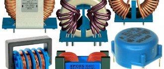
Varieties
The following types of electric chokes are currently used:
- Turn-free. A turn-free electromagnetic choke consists of a ferrite ring and a conductor passed through it. It has a great external resemblance to a conventional resistor. The main purpose of the device is to suppress high-frequency interference.
- For alternating current. Designed to create reactive and inductive reactance, a current ripple filter in voltage converters.
- Smoothing. An electronic smoothing choke is used to reduce the variable part of the voltage or current on the input and output parts of the electrical circuit. Such devices are used in current converters. Smoothing chokes are connected in series to the load, thereby causing smoothing of the alternating part of the current, passing through only the direct component of the linear current. A feature of such elements is their high inductance.
- Saturation. The saturation choke is used for alternating current circuits as an inductive reactance regulator. The main difference between the device is the presence of 2 windings: a working winding, for connecting to alternating current, and a control winding, which is connected directly to an electrical circuit with direct current. To operate such a device, a variant of the nonlinearity of the magnetic circuit curve is used. In other words, the DC current regulation depends on the amount of magnetization of the core.
Modern electrical engineering requires a significant reduction in the overall parameters of electrical circuit elements. On surface-mounted circuits, provided they are heavily loaded with parts, so-called chip filters are used. Such elements do not have a wire. The coil is formed from several layers of ferrite. The main purpose of chip filters is to reduce high-frequency interference in complex electronic circuits.
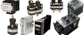
In addition, there are starting devices. They are used as braking and starting current limiters for electric motors. In electrics, three-phase varieties are used to start a powerful electric motor. They are distinguished by a large amount of inductance.
Parallel oscillatory circuit.
If you connect an inductor and a capacitor, you get a very interesting element of radio engineering - an oscillatory circuit. If you charge a capacitor or induce E.M.F. in the coil using an electromagnetic field, the following processes will begin to occur in the circuit: The capacitor, when discharged, excites an electromagnetic field in the inductor. When the charge is depleted, the inductor returns the stored energy back to the capacitor, but with the opposite sign, due to the E.M.F. self-induction. This will be repeated again and again - electromagnetic oscillations of a sinusoidal shape will appear in the circuit. The frequency of these oscillations is called the resonant frequency of the circuit, and depends on the values of the capacitor capacitance (C) and the inductance of the coil (L).
A parallel oscillatory circuit has a very high resistance at its resonant frequency. This allows it to be used for frequency selection (selection) in the input circuits of radio equipment and intermediate frequency amplifiers, as well as in various master oscillator circuits.
Characteristics calculation
The electric throttling device is marked on the body with its main characteristics. But if there is no marking or the device is intended to be manufactured independently, then it is necessary to carry out a preliminary calculation of the main parameters of the device. How to make such a calculation will be described below.
When calculations are made, a simple formula is used to calculate inductance:
To confirm that the calculated number of turns is correct, you can use the tester in inductance measurement mode. This will help confirm that the required number of turns is correct.
Calculation of the cross-section of the wires of the primary winding of the transformer
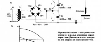
Diagram of a welding transformer.
The theory of transformers is complex in that it is based on the laws of electromagnetic induction and other phenomena of magnetism. However, without using complex mathematical apparatus, it is possible to explain how a transformer works and whether it can be assembled independently.
The transformer can be manually wound on a metal core assembled from transformer steel plates. It is easier to wind on a rod or armored core than on a toroidal one. You should immediately note that the image clearly shows the difference in the thickness of the wires: the thin wire is located directly on the core, and a larger number of turns is clearly visible in it. This is the primary winding. The thicker wire with fewer turns is the secondary winding.
Without taking into account the power losses inside the transformer, let's calculate what the current I1 should be in its primary winding. The ideal network voltage is U=220 V. Knowing the power consumption, for example, P=5 kW, we have:
I1 = P:U= 5000:220=22.7 A.
Based on the current in the primary winding of the transformer, we determine the diameter of the wire. The current density for a household welding transformer should be no more than 5 A/mm2 of wire cross-section. Therefore, for the primary winding you will need a wire with a cross section of S1 = 22.7:5 = 4.54 mm2.
Using the cross-section of the wire, we determine the square, its diameter d without taking into account the insulation:
d2=4S/π=4×4.54/3.14=5.78.
Taking the square root, we get d=2.4 mm. These calculations were performed for copper wire cores. When winding wires with an aluminum core, the obtained result must be increased by 1.6-1.7 times.
For the primary winding, copper wire is used, the insulation of which must withstand high temperatures well. This is fiberglass or cotton insulation. Rubber and rubber-fabric insulation is suitable. Wires with PVC insulation should not be used.
How to independently and beautifully create a living room design?
Connection diagram
Chokes are often found in power supplies and fluorescent lamps. Connection to the inductor circuit for such options will be presented below in the article.
Fluorescent lamp
In such a circuit, the inductor acts as a starting and smoothing device. It is connected in series with the lamp. In this case, a starter is also used in conjunction with it. With this connection, the inductor uses the following operating principle:
- Alternating current flows through the circuit.
- A fluorescent lamp does not turn on when cold due to its high resistance. The flowing current does not start the lamp, but heats its cathodes, and then flows to the starter.
- The moving contact heats up inside the starter. After heating, the contact closes the circuit.
During the heating of the cathodes and the starter, current accumulates in the inductor circuit. When the starter closes, the current is displaced by the choke and the starter itself is discharged. During discharge, electrons at the cathodes of the lamp begin to move. They come into contact with the gas, and the lamp lights up. The diagram of a fluorescent lamp, consisting of a choke, two starters and two fluorescent lamps, is presented below.
power unit
Beginner radio amateurs often have this question: why do you need a choke in the power supply? It is necessary for two reasons:
- To smooth out the alternating current component.
- To smooth out pulsations.
As a rule, the chokes in these blocks are installed after the diode bridge directly at the output, which means they already work with direct current. When the voltage increases or there is a short circuit, the inductor smoothes out a significant part of the ripple. With stable operation of the power supply, the device smoothes out high-frequency interference by passing only direct current into the circuit without any fluctuations. Such a damper also acts as an additional resistance, which significantly reduces the voltage at the bridge output. The choke and such a connection diagram are shown in the figure below.
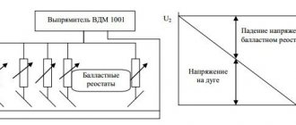
Calculation of chokes with a magnetic core for an arbitrary current shape
Many works are devoted to the calculation of chokes (inductive coils, reactors), for example [1-4]. However, these works describe calculations for reactors operating at either alternating current or direct current. For coils operating with an arbitrary current waveform, there is no calculation method. There is no method for calculating chokes operating with a given time constant or with given losses in the winding.
The main requirement for calculating chokes is to obtain a given magnetizing inductance at a given current. The optimal dimensions of the inductor are obtained by introducing a non-magnetic gap into the magnetic circuit.
When calculating a transformer, the task is to obtain a given leakage inductance at a given voltage and current. The presence of a non-magnetic gap only worsens the quality of the transformer.
In a choke, the law of change in induction is set by current, in a transformer - by voltage. In other words, in a choke the core is magnetized by current, in a transformer by voltage.
There are several typical non-sinusoidal modes of operation of the inductor.
- The minimum and maximum current values are close to each other (for example, the difference does not exceed 5-10%, Fig. 1a, 1b). This mode is called operation of the inductor with pulsating or direct current. Filter chokes, a choke in the demagnetization circuit of pulse transformers, a linear charging choke, etc. operate in this mode.
The difference between the maximum and minimum values is called the drop (sometimes the peak-to-peak), and half of this value is the amplitude of the alternating current component. The direct current component I= is close to the maximum and minimum values, and with an asymmetrical shape of the current curve it is not equal to the arithmetic mean of the maximum and minimum values.
- The minimum and maximum current values are much different from each other (for example, one is equal to 5-10% of the other, Fig. 1c). The mode is usually called pulsed. The resonant charging choke operates in this mode. The DC component is noticeably less than the maximum current value.
- The minimum and maximum current values are close in absolute value, but have opposite signs; the constant component is significantly less than each of them (Fig. 1d). The mode is usually called alternating or mixed.
- The minimum and maximum current values are close in absolute value, have opposite signs, and the constant component is zero (Fig. 1e). There is alternating current mode. In this mode, chokes and reactors operate in alternating and sinusoidal current circuits.
In all modes, the constant component of the voltage induced on the inductor is zero. Otherwise, the induction in the magnetic circuit would continuously increase.
Changes in induction repeat changes in current; the constant component of the current determines the constant component of induction. The direct components of current and induction do not cause energy losses in the magnetic circuit (although they can affect losses caused by the alternating component [5]).
The current flowing through the winding causes energy loss and heating of the winding, and this is a determining factor in the operating mode and calculation of the inductor. Let us note in passing that, unlike a constant current inductor, storing energy in a capacitor at a constant voltage is not accompanied by practically noticeable losses.
The variable component of induction causes energy losses in the magnetic circuit. In modes a) and b) there is a large constant component B=, proportional to I=, which does not cause energy losses in the core, and a small variable component Bпm, proportional to ΔI / 2, causing small losses. In mode c), the variable component Bpm is significant (proportional to Im/2), it is comparable to the constant component. In modes d) and e) there is only a variable component Bпm, it is comparable to the variable component of mode c). It is necessary to distinguish the maximum value of the variable component of induction Bpm from the maximum value of the variable component of induction Bm in the core (see modes a, b and c).
The inductor and transformer have the same components: magnetic core and windings. The task of constructive calculation of both the inductor and the transformer is to determine the main geometric dimensions of the magnetic circuit, the number of turns of the windings, and the cross-section of the winding wires. For the throttle, you also need to find the size of the air gap.
The initial data for calculating the inductor are: L - inductance of the inductor; law of change of current i (t) with known parameters: amplitude Im, amplitude coefficient of the current pulse ka = Im/I, where I is the effective value of the current during the pulse, frequency and duty cycle of the pulses ν = Tu / T (Fig. 1c); R is the resistance of the winding to direct current or τ = L / R is the time constant, or the quality factor of the circuit Q = ωτ, or losses in the winding P = I2 × R.
If the current is alternating, then the energy losses in the magnetic circuit can be comparable to the ohmic losses in the inductor winding, that is, the losses in the winding make up part of the allowed losses in the inductor, which means that the inductor must be calculated with the winding time constant τ = L / R greater than the specified total time constant .
Next, armored and rod types of chokes will be considered. The most unfavorable cooling conditions, due to the closed magnetic circuit with coils, are the rod type with coils on both rods. Specific losses for these magnetic cores, as a rule, should be 3-5 W/kg, for the rest 7-10 W/kg.
Preliminarily, based on the accepted value of the specific losses in the magnetic circuit with a known law of change in induction, the permissible amplitude of the variable induction component and its maximum value Bпm or the induction difference ΔBu are determined.
Let us briefly consider the choice of operating mode of magnetic cores.
The simplest is to select the working induction to operate at very low frequencies - 0-20 Hz. Here, laminated, twisted magnetic cores made of conventional transformer steels with a thickness of 0.3-0.5 mm can be used.
At frequencies of tens and hundreds of hertz
the traditional selection of materials and operating modes must be carried out.
At frequencies of several tens of kilohertz
losses in the magnetic circuit are decisive when choosing the brand and thickness of the magnetic material. At high frequencies, eddy losses can be controlled by choosing the material thickness. Particularly thin tapes are produced from permalloy (10-20 microns) and amorphous or nanocrystalline materials (25 microns). Hysteresis losses do not depend on the thickness of the material and at high frequencies become decisive. Materials with a narrow hysteresis loop or with a high initial magnetic permeability should be selected. Here, amorphous alloys have practically no advantages compared to thin, highly alloyed alloys (permalloy).
A radical way to reduce losses is always to reduce the variable component of induction down to tenths of a Tesla, i.e. hundreds of mT. In modes a) and b) this reduction is performed automatically; if necessary, further reduction should be carried out together with the choice of a small value of the constant component.
At low operating induction, the dimensions of the magnetic core and inductor increase greatly.
To increase induction and reduce the size of the throttle, intensive airflow or oil cooling can be used, increasing heat removal from surfaces by 1.5-2 times. Ferrite cores with natural cooling allow working with an induction of 0.3-0.4 T.
Above 10-15 kHz
- area of operation of ferrite cores or conventional alloys with very low operating induction values. Unfortunately, the production of large-sized ferrite cores encounters serious technological difficulties.
The choice of working induction is made by calculation or according to graphs in reference materials [6].
An objective way to control the quality of calculations is to experimentally check the thermal regime of the magnetic circuit at a selected value of the variable induction component on an experimental core or its model (Fig. 2). A control winding of thin wire is wound onto the core with a number of turns suitable for the pulse amplitude of the control generator w
= Ug × τu / (s × ΔBu). Such a generator has relatively low power, since it provides magnetization of the core at idle speed.
Those sections of the core on which the winding will be located can be covered with heat-insulating material.
Checking the thermal conditions of the magnetic circuit when magnetizing the core simultaneously with both direct and alternating current encounters significant difficulties. The selection of the magnetic material and the magnitude of the working induction completes the first stage of calculating the inductor.
In subsequent conclusions, the assumption is made that the thermal regime of the magnetic circuit does not affect the thermal regime of the coil. When thermally calculating the cooling surface, the coils in contact with the core are not taken into account. Likewise, when thermally calculating a magnetic core, surfaces in contact with the core should not be taken into account.
The second stage is the calculation of the windings.
We take the cross section of the magnetic circuit (the first row of the table) as the main variable. The cross section is the only geometric parameter included in the formula of the law of electromagnetic induction. The law is invariant with respect to the shape of the section. Through the cross section for the selected throttle configuration, all its other dimensions can be determined, for example, and
= 0.5 ×
s
1/2 (second row of the table, first column),
in
= 2
a
,
h
= 4.6
a
, length of the average field line
l
c = (4.6 + 4.6 + 2 + 2 + 3.14) ×
a
=
k
2 ×
s
1/2 (third line of the table), coil length
l
m =
k
4 ×
s
1/2, window cross-section
s
ok =
k
6 ×
s
.
The choice of cross-section s as an argument is convenient in that after determining the main geometric dimensions of the transformer, a rod with a rectangular cross-section can be replaced by a rod of any shape with an equal cross-section (for example, round, stepped) while maintaining the basic electrical parameters of the inductor. The table shows a number of typical designs of armored and rod-type chokes. The first two are armored with a square and rectangular cross-section of the magnetic circuit, the next two are rod-shaped with a square and rectangular cross-section of the magnetic circuit with coils on each rod.
The problem is considered without taking into account the nonlinearity of the webampere characteristics and under the assumption that there are no additional cooling channels in the windings.
To increase the energy capacity of the inductor, a non-magnetic gap, usually called an air gap, is introduced into its magnetic circuit. The gap area s, taking into account the coefficient of filling the section with magnetic material and buckling, is related to the steel section by the relation s × kc= sc
.
Since the same magnetic flux passes along the magnetic circuit, the induction in gap B will be close to the induction in the magnetic circuit Bc:
where μ0 = 1.26 × 10⁻⁶ H/m magnetic constant, ks
= 0.75-0.95 - the ratio of the active cross-section of the magnetic core to the gap cross-section, taking into account buckling [1].
The magnetomotive force (MF) of the winding is distributed between the magnetic core and the gap:
By definition, inductance is the proportionality coefficient between flux linkage and current, that is
If a significant air gap is introduced into the magnetic circuit, that is,
The absence of explicit core dimensions in the formula for determining inductance indicates that the inductance of the inductor is determined primarily by the dimensions of the air gap. Physically, this means that the energy of the inductor is determined by the energy of the magnetic field of the gap.
Strictly speaking, a choke with a magnetic core is a nonlinear element of an electrical circuit, but its nonlinearity usually does not exceed a few percent. Neglecting the first term of the sum in the denominator of formula (5) with a gap of 1% and μ=10,000 gives an error in the calculation of also about 1%. Greater accuracy in the calculation of chokes is not required, since with such accuracy it is almost impossible to determine even the size of the air gap.
Maximum energy stored in the inductor at a given induction B mc
, turns out to be proportional to the magnetomotive force (MF)
(Iw)
developed by the winding:
where Bm=Bmckc
— maximum value of induction in the gap;
Bmc
is the maximum value of induction in the core material.
The maximum current value is related to the effective ratio:
Let us show that the MMF of the coils of each magnetic circuit has a certain limiting value, limited by the degree of heating of the coils. Let w winding turns be placed in a core window with area Sok, the window filling factor with conductive material is km
= 0.4, then
where ρ = 1.85 × 10⁻⁸ Ohm.m is the resistivity of the conductor material; l m
1 - average winding turn length.
To ensure that the winding resistance and the released power do not increase with increasing operating frequency of the current, the inductor windings must be wound with litz wire. The Litz wire core consists of many insulated conductors. The diameter of one conductor should not exceed the value [7]:
Power released in the coil and dissipated by its surface
where Socool is the cooling surface of the winding, that is, the surface of the winding with the exception of the parts facing the rod; q
— permissible heat flux density (when the winding surface is overheated compared to the surrounding air, equal to 55 °C,
q
= 650 W/m2).
If the choke is high-voltage and the winding is filled with a high-voltage compound or a frame with thick walls is used, the window will not be completely used. The same situation arises if the real core has a window of smaller dimensions than the proportions accepted in the table. The introduction of a window utilization factor β < 1 allows us to take these cases into account.
Thus, the limiting MMF equal to
depends on the geometric dimensions of the coil, the coefficient of heat transfer from the surface and the resistivity of the wire and the utilization factor of the window.
The cooling surface, window area, core cross-sectional area, average turn length for a selected core shape can be expressed in terms of the gap section s (for example, in the fourth column of the table, a
= √
s
/ 2,
h
= 4
a
= √
s
/ 2) and therefore
for common geometric shapes of magnetic circuits are given in the table (the calculations assume the use of the SI system).
Taking into account (15) and (11), the energy in the throttle
Solving this equality for s
, we'll find
This is the first basic formula for determining the cross-section of the magnetic circuit of the designed choke; then the remaining dimensions can be determined, for example, a
= √
s
for a square or
a
= √
s
/ 2 for a rectangular cross-section of the core magnetic circuit, window height
h
= 4
a
, etc. However, if you calculate the inductor only based on energy, it may turn out that the winding will have a very high resistance R, which will lead to an unacceptably low time constant τ = L / R or circuit quality factor Q = ωτ or unacceptably large losses P, that is, to low Circuit efficiency. To determine the design dimensions of the inductor through the time constant τ, you can obtain formulas that take into account and do not take into account restrictions on induction, maximum MMF, and inductor energy. (For example, the relation (8) to (12) gives an equation that includes only design parameters.) Relations that are inconvenient for practical use are not given. Relationships that are inconvenient for practical use are not given.
The intrinsic time constant and power losses are related:
If it is equally important to have both a given energy reserve and the required time constant, we write the product ( W m
τ):
Simultaneous fulfillment of the requirements for storing the necessary energy and obtaining a given time constant or limiting power losses sometimes leads to the need to select the operating mode of the inductor when the MMF of the coil is up to the limit. Solving equation (19) for s, taking into account (9) and (13), we obtain the second formula for determining the cross-sectional area of the magnetic core:
Values of the coefficient k sWτ
are given in the table.
Of the two sections found by (17) and (20), the larger one should be selected and further calculations should be carried out with it. We find the non-magnetic gap under condition (7) from (4):
kl coefficient values
depend on the core size
s
.
Experience shows that with a gap equal to 10-15% of the length of the average power line, the necessary parameters of the inductor can be obtained from the winding without a magnetic core, however, a magnetic core is often used with this ratio of parameters, since it protects the nearby part of the space as a screen and metal structures from exposure to a strong magnetic field.
The number of turns of the winding can be easily found from
At the maximum MMF, the maximum permissible current density in the winding wire can be estimated:
k coefficient values
Δ are also given in the table.
Taking into account the found relationships, the volumes of winding copper and core steel can be determined.
Taking into account the density of copper and steel and the mass of structural elements (10%), the mass of these parts and the total mass of the inductor (kg) are equal to:
coefficient values kmg
,
kсg
and
kgs
are given in the table.
| Throttle design type | ||||||||
| Cross-sectional area of the magnetic gap, m2 | s | s | s | s | ||||
| Short cross-sectional side of one magnetic circuit ring, m | a = (s/4)1/2 = 0.5s1/2 | a = (s/8)1/2 = 0.35s1/2 | a = s1/2 | a = (s/2)1/2 = 0.71s1/2 | ||||
| Length of the average field line through the root of s, lc = k2s1/2 | k2 | 8,17 | 5,79 | 14,34 | 10,17 | |||
| Length of the turn through the root of the section s, lм = k4s1/2 | k4 | 7,14 | 6,48 | 6,51 | 6,04 | |||
| Window area through section s, Sok = k6s | k6 | 2,3 | 1,15 | 6,40 | 3,20 | |||
| Cooling area through s, sохл = k8s | k8 | 31,62 | 16,96 | 81,83 | 46,52 | |||
| Cooling surface of the magnetic circuit, through s, sохлs = k10s | k10 | 31,22 | 25,35 | 22,16 | 15,82 | |||
| Allowed specific losses in the magnetic circuit, pud = k12/s1/2, W.m/kg | k12 | 0,37 | 0,43 | 0,15 | 0,15 | |||
| Magnetizing force coefficient | kIw | 1,89 × 10+5 | 1,03 × 10+5 | 5,32 × 10+5 | 2,94 × 10+5 | |||
| Coefficient for determining cross-sectional area in terms of energy and time constant | ksWτ | 2,42 × 10⁻³ | 3.07 × 10⁻³ | 1,55 × 10⁻³ | 1,98 × 10⁻³ | |||
| Current density determination factor | kΔ | 4,11 × 10+5 | 4,47 × 10+5 | 4,15 × 10+5 | 4,60 × 10+5 | |||
| Coefficient for determining the mass of the winding | kmg | 5,85 × 10+4 | 2,65 × 10+4 | 14,8 × 10+4 | 6,88 × 10+4 | |||
| Core mass determination factor | kcg | 5,42 × 10+4 | 3,84 × 10+4 | 9,51 × 10+4 | 6,74 × 10+4 | |||
| Coefficient for determining the mass of the throttle over the cross section | kgs | 12,4 × 10+4 | 7,15 × 10+4 | 26,8 × 10+4 | 15,0 × 10+4 | |||
| Factor for determining throttle mass through energy | kgW | 3,72 | 3,61 | 3,31 | 3,08 | |||
| Factor for determining the throttle mass through energy and time constant | kgWτ | 14,72 | 12,14 | 16,29 | 13,20 | |||
The cross-sectional value from (17) and (20) can be substituted into the formula for determining the total mass of the throttle (26). We obtain a formula for calculating the mass of the throttle through energy:
and a formula for calculating the mass of the inductor while simultaneously specifying both the energy and the time constant or the energy and power losses:
the values of the coefficients kgW and kgWτ are given in the table.
From an examination of these coefficients, it is clear that for energy storage, a rod choke with a rectangular cross-section of the magnetic circuit is preferable, and for obtaining a given time constant, an armored choke, also with a rectangular cross-section, is preferable.
Now the law of increasing the throttle mass with increasing its energy can be found with full use of the window β = 1. Specific energy of the throttle
Value kud
is not constant and depends on the working induction and other coefficients.
With increasing energy, the specific energy of the inductor slowly (degree of 1/7) increases. For example, with constant current, ka
= 1;
ν = 1; induction Bmc
= 1.5 T;
ks
= 0.85, we obtain
ksp
≈ 0.41 and at an energy
Wm of
10 J the specific energy is 0.56 J/kg, and at an energy of 1000 J it is 1.1 J/kg.
Processing of statistical data on a variety of chokes produced by the domestic industry showed this dependence and served as the basis for the research presented in the article.
We illustrate the procedure for applying formulas for engineering calculations with examples.
Example 1.
It is required to design a choke with an inductance of 3 H, with an average current of 32 A, with ripple ±10% (Fig. 1a), with a maximum induction value of
Bmс
= 1.5 T, the winding resistance should not exceed 5 Ohms.
We preliminarily determine the maximum value of current Im
= 32 × 1.1 = 35 A; with a small pulsation depth, the effective current is almost equal to the average I = 32 A and the maximum energy value is:
throttle time constant τ = L / R = 3 / 5 = 0.6 s.
We select a choke with a rod-type magnetic core with a square (round) cross-section according to (17):
We determine the size of the same section taking into account the requirements for the time constant according to (20):
To accumulate energy, a larger inductor is required than is required to obtain the product of the given values of the time constant and energy.
Based on the selected cross-section, the remaining dimensions of the throttle can be determined (see table). For example, a
= √
s
= 0.18 m;
window height h
= 4
a
= 0.72 m;
window width 1.6 a
= 0.288 m;
window area Sok
= 0.22 m2 and so on.
We find the working MMF of the winding from (11):
when calculating the choke by energy, the MMF coincides with the limit (15):
We find the air gap using (21):
A gap comparable to the cross-sectional dimensions of the magnetic core must be made in the form of several separate spaces. Number of winding turns according to (23):
To check the correctness of the calculation, we find the inductance of the inductor using (8):
Wire size:
Allowable current density (24):
To estimate the size of the throttle, let’s find its mass (26):
The commercially produced reactor EROS-1000/10 has the same inductance and operating current. Its mass is 1500 kg. In this reactor, the winding is sectioned to improve cooling.
Example 2.
It is required to calculate a choke with an inductance of 1 Hn with an amplitude of a half-sinusoidal (
ka
= √2) current of 1.6 A, with a duty cycle of 1.3, that is, I = Im /
ka
/ √ν = 1 A (Fig. 1c), power losses in winding should not exceed 10 W. The maximum value of induction in the magnetic circuit is assumed to be Bmc = 1.4 Tesla.
Obviously, for ka
= √2 and v = 1 we obtain a choke for operation in a sinusoidal current circuit.
Throttle Energy:
We select an armored magnetic core with a square cross-section of the rod. We first determine the cross section of the core without taking into account the requirements for the time constant or power losses according to (17):
We find the cross section of the rod taking into account the loss requirements:
P = I2R
, that is,
R = P/I2
= 10/1 = 10Ω, and τ =
L / R
= 1 / 10 = 0.1 s;
according to (20):
We see that to meet the requirements for power losses, a magnetic circuit with a large cross-section is required. A standard magnetic core ШЛ-32A32 with a geometric cross-section of 10.2 cm2 can be used.
We find the working MMF of the winding from (11):
The winding of such a magnetic circuit could develop the maximum MMF:
With the initial data of this example, the maximum capabilities of the winding cannot be realized. It can be shown that the wire will be underutilized in terms of current density, but the cross-section of the wire cannot be reduced, as this will lead to an increase in winding resistance and a decrease in the quality factor of the inductor. Calculations can be continued similarly to example 1. For example, the mass of the inductor magnetic circuit will be according to (26):
Example 3.
It is required to estimate the mass of the armored choke with a time constant of 0.1 s for an energy reserve of 1.3 J at a maximum value of induction in the magnetic circuit of 1.4 Tesla.
From (27) we find:
Further, other design options and other size ratios can be analyzed in order to refine one or another optimization (for specific sizes of magnetic cores, wires, weight, volume, cost, introduction of cooling channels, etc.).
Literature
- Mankin E.L. Calculation of reactors with a steel magnetic core and a gap // Electricity. 1959. No. 7.
- Sternin V. G., Karpensky A. K. Current-limiting reactors. M.: Energy, 1965.
- Karasev V.V., Kubarev L.P., Leites L.V. Generalized analytical method for optimizing and assessing reactor parameters // Electrical engineering. 1977. No. 4.
- Leites L.V. Electromagnetic calculations of transformers and reactors. M.: Energy, 1981.
- Babin S.V., Karasev V.V., Filippov F.E. Characteristics of magnetic cores of current transformers under simultaneous exposure to constant and alternating magnetic fields // Electrical industry 1981. Vol. 6.
- Cherkashin Yu. S. Process and energy of magnetization of a sheet magnetic circuit at rectangular voltage. Electricity 1978. No. 6.
- Cherkashin Yu. S. Design of inductors for high-power radio devices. — Radio engineering. 1986. No. 6.
Examination
Before this, we found out what a choke is for, what this device consists of, where it is used and on what principle it works. Now let's try to find out how to test this element for functionality. Using a multimeter, you can always check the integrity of the element and the value of its inductance.
Inductance
To measure inductance, you will need a tester with a mode for measuring this parameter. Such capabilities of the multimeter are indicated by the letters “N” or “Gn”. This parameter is measured as follows:
- You need to set the multimeter to inductance measurement mode.
- Next, you will need to make sure that the device being tested is disconnected from electricity.
- Connect the measuring probes to the contacts of the element.
The device should show an inductance value close to those indicated on the device body.
Resistance
Measuring the resistance will help you find out the condition of the coil. The check in this case looks like this:
- The choke must be disconnected from the circuit.
- Switch the tester to resistance measurement mode.
- Connect the measuring probes to the contacts of the device.
An infinitely large resistance will indicate a break in the internal winding. If there is no resistance at all, this indicates a short circuit. The resistance value should be close to the characteristics indicated on the device body.
You can make sure that there is no short circuit by switching the tester to the “continuity” mode. The tester beeps to indicate the presence of a short circuit.