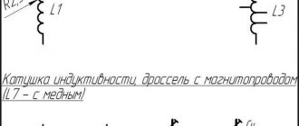
Homemade chokes based on MLT resistors and 2.8mm ferrite cores. Making a choke by winding a conductor on an MLT resistor is an inexpensive and simple way to obtain a small-sized electronic component, which can often be found in circuits of radio transmitters, radio receivers, transceivers, televisions and other electronic equipment.
Rice. 1. Homemade chokes based on MLT resistors.
Below we will present a simple calculator form for calculating the inductance and the number of turns of wire for chokes that are made by winding on resistors MLT-0.125, MLT-0.25, MLT-1, MLT-2, thus we get a choke without a core, with a convenient frame serves as the housing of a high-resistance resistor.
Main characteristics
In most cases, chokes have significant dimensions. To make devices compact without compromising technical characteristics, the inductor is replaced with a stabilizer, which is essentially a powerful transistor. The result is an electronic throttle. However, a device of this type is a semiconductor, so it is not practical to use it in high-frequency devices.
The electronic choke must be selected according to several parameters, the main one of which is inductance, measured in H. Also important technical characteristics of the devices are:
resistance, which is taken into account with direct current; voltage change within acceptable limits; bias current – the nominal value is used.
When choosing a device, first of all you need to focus on goals and objectives, for which you need a choke in electrical circuit diagrams. The use of magnetic cores in electric chokes makes it possible to ensure compactness of the devices while maintaining the same inductance values. Ferrite and magnetodielectric compounds, due to their low capacitance, can be used in wide frequency ranges.
Formula for calculation
In most cases, very precise inductor inductance is not a critical factor, so a coreless inductor can be wound on the body of the MLT resistor. In order to calculate the required number of turns, you can use the formula:
N=32*SQRT(L/d)
Where:
- N is the required number of turns,
- L is the required inductance of the inductor in μH,
- d is the diameter of the frame (in this case, the resistor frame) in mm.
SQRT is the square root of a number function.
To make calculations, you can use our online calculator:
Self-production
To make your own throttle, you need to correctly calculate its design. To do this, use a simple formula for calculating inductance: L=0.01*d*w 2 /(L/d+0.44), where d is the diameter of the base (cm), L is the length of the wire (cm), w is the number of turns . Moreover, if you have a multimeter with the ability to change the inductance, then the exact number of turns can be selected using it.
The winding method using this formula involves laying turn to turn. For example, it is necessary to select a magnetic circuit for a choke with an inductance of one μH, designed for a current I = 4A. A 2000 NM core of standard size K 16 x 8 x 6 is taken. According to the reference book, the initial inductance coefficient is ALH = 1.36 μH, and the magnetic path length is le = 34.84 mm. Accordingly, the number of turns will be N= (L/ALH)0.5= (1/1.36)0.5 = 0.86. If we take N=1, then at a given current the magnetic field strength in the core will be equal to H= 4*1/(34.84*10−3)= 114 A/m.
Thus, the inductor is a coil characterized by inductance. Thanks to its properties, it can accumulate magnetic power and then release it into the circuit in the form of electrical energy. Moreover, the use of the element also makes it possible to suppress the alternating current component in the circuit.
A choke (translated from German as “reduce”) is a type of inductor. The main purpose of this element of the electrical circuit is to “delay” (reduce for a certain period of time) the influence of currents of a certain frequency range. At the same time, it is almost impossible to sharply change the current strength in the coil - here the law of self-induction comes into force, due to which additional voltage is formed at the output.
A choke is needed in an electrical circuit when it is necessary to suppress the alternating component of the current (for example, noise), significantly reduce ripple in the network, and also limit or separate various frequency signals in accordance with the task (isolation or decoupling).
In electrical and radio engineering, alternating current is used in the range from units to hundreds of billions of Hz. (1 hertz is one oscillation per second).
Conventionally, such wide boundaries are divided into several sections:
- low (audio) frequencies (20 Hz – 20 kHz);
- ultrasonic frequencies (20 – 100 kHz);
- high and ultra-high frequencies (from 100 kHz and above).
The latter consists of turns of insulated wire wound onto a steel core made of insulated plates (to avoid the occurrence of Foucault currents), and has high inductance. Such a coil is characterized by strong resistance to any changes in current in the circuit: it supports it when it decreases, and restrains it when it sharply increases.
Also, chokes are widely used in the implementation of various high-frequency electrical circuits. In this case, their design can be single or multilayer, while cores (both steel and ferromagnetic) are often not used. Sometimes ordinary resistors or plastic frames are used as the basis for winding. In the range of long and medium waves, special sectional wire winding is also used to ensure the specified parameters.
The latter indicator is widely used in calculations of oscillatory circuits.
The use of magnetic cores makes it possible to significantly reduce the dimensions of chokes with the same declared inductance parameters. At high frequencies, ferrite and magnetodielectric compounds are used, which, due to their small intrinsic capacitance, allow them to be used over a wide range.
According to their purpose, this type of inductor can be divided into the following types:
- alternating current. Used for current limiting in the network; for example, during the start of an electric motor or pulsed PVEP.
- saturation. The main area of application is voltage stabilizers.
- smoothing. Designed to weaken ripples of already rectified current.
- magnetic amplifiers (MU). They are inductor coils, the core of which is magnetized by direct current. By changing the parameters of the latter, you can change the inductive reactance.
Three-phase chokes are also available for use in appropriate circuits.
Today, various types of chokes are widely used to solve a variety of engineering problems.
Watch an interesting video about electric throttles below:
Making a throttle
To make a choke, you need to choose a suitable frame - in our case, this is a resistor of a certain power and, accordingly, dimensions. Below are photos of domestic and foreign resistors with the designation of their power.
Rice. 2. MLT resistors and foreign power resistors.
Rice. 3. An example of winding a choke on an MLT-0.5 resistor.
Resistors with high resistance are suitable for winding the inductor, for example: 100 kOhm, 200 kOhm, etc. It is important that the resistance of the resistor is large, otherwise the quality factor of your homemade inductor may turn out to be poor.
An example of winding in uniform layers is shown in Figure 3.
For winding, you can use thin enameled wire (PETV) or silk-insulated wire (PELSHO) with a diameter of 0.1-0.2 mm; it is important that all the turns wound with such wire fit on our resistor frame.
After winding, each end of the wire is soldered to the terminals of the resistor, and you can drip a little glue onto the coil on top so that the turns do not spread later.
Marking of small devices
Devices for electronic boards have dimensions of no more than 2-3 cm. It is almost impossible to apply readable markings in digital or letter designations. For this purpose, color coding of electronic chokes is used. Chokes in the diagrams are depicted in the form of a spiral with a parallel line.
Several colored rings are applied to the cylindrical body of the radio component. The first two bars (from left to right) indicate the inductance value, measured in mHenry. The third bar indicates the multiplier by which the inductance number should be multiplied. The fourth ring expresses the permissible deviation in % from the nominal value. If it is not on the body of the part, then the tolerance is considered to be within 20%.
Color coding table
For example, the colors of the rings are in the following order: brown, yellow, orange and silver. This means an inductance value of 14 mH, where the deviation tolerance is 10%.
Technological progress does not stand still. Every year new analogues of outdated models appear. The development of new technologies in all areas of human activity requires the improvement of radio components, including chokes.
Purpose
Many people are interested in what a throttle is and what it looks like. The device is made in the form of an iron transformer, the only difference is the presence of one winding. The coil is wound onto a transformer steel core, with the plates separated and not in contact with each other to reduce eddy current.
The electronic choke is characterized by a high level of inductance up to 1H; the coil effectively counteracts changes in current in the electrical circuit. When the current decreases, the coil maintains it, and in the event of a sharp increase, the coil ensures limitation and prevention of a sharp jump.
When considering why a throttle is needed, the following goals should be mentioned:
- reduction of interference;
- smoothing of electric current pulsations;
- accumulation of energy in a magnetic field;
- separation of parts of the circuit at high frequency.
Why do you need a throttle? Its main purpose in an electrical circuit is to delay current in a specific frequency range or accumulate energy in a magnetic field.
The importance of the choke is explained by the fact that fluorescent gas-discharge lamps (for example, household lamps, street lamps) do not function without a choke. It acts as a voltage limiter applied to the electrodes of the gas-discharge lamp
Throttling devices also generate the starting voltage required to create an electrical discharge between the electrodes. This ensures that the fluorescent lamp turns on. The starting voltage is designed for only a fraction of a second. Thus, the choke is a device responsible for turning on the lamp and its stable operation.
How to calculate the interturn capacitance of the inductor winding?
In the inductor, between the turns, layers and metal objects around the inductor, there is some potential difference that creates an electric field. To assess the influence of this field, the concept of interturn capacitance or the inductor’s own capacitance is introduced, the value of which depends on the size and design features of the inductor.
The interturn capacitance C of the winding, being a parasitic parameter, together with the leakage inductance and the inductor’s own inductance form various types of filters and oscillatory circuits. Although this parameter is of small importance, nevertheless, in certain conditions it has to be taken into account, but accurate calculation is difficult due to the large influence of various design parameters, primarily, the relative position of the turns of the wire among themselves. So, bulk-wound coils have the greatest interturn capacitance, and coils with “Universal” type winding or sectional coils have the smallest.
The interturn capacitance Cc of the inductor can be represented as the sum of the capacitances between the inner layer of the winding and the magnetic circuit C1 and the interlayer capacitance inside the winding C2
The capacitance between the inner layer of the winding and the magnetic core can be determined from the empirical formula
where εа is the absolute dielectric constant of the medium around the conductor, εа = εεr,
εr – relative dielectric constant,
ε – electrical constant, ε = 8.85 * 10-12 F/m,
r – radius of the cross section of the wire,
a is the distance between the magnetic core and the axis of the wire,
n – number of turns in the layer,
р1 – perimeter of the turn of the inner layer of the winding.
The relative dielectric constant is taken for the material of the inductor frame; if the design is frameless, then, accordingly, the permeability of air or conductor insulation, depending on the required accuracy.
The capacitance between the winding layers is also calculated using the empirical formula
where рср is the perimeter of the middle turn of the winding,
b – distance between the axes of turns in adjacent layers,
m – number of layers.
In this case, the dielectric constant is taken for the interlayer insulation material.
In all cases, it is necessary to reduce the interturn capacitance of the winding. For this purpose, various types of windings and materials for frames and interlayer insulation with a low dielectric constant are used.
Winding coils and chokes
We bring to your attention WINDING PRODUCTION various inductors:Our company will carry out WINDING of transformers on frames and chokes on ferrites, coils for electromagnets, frameless coils and other winding products.
Row winding of open coils according to customer parameters, R&D. •High speed winding equipment available. •Through impregnation with varnish is carried out.
•The casting of frames of our own production in Moscow has been mastered; it is possible to manufacture molds for frames according to the Customer’s drawings.
•Production of frames from textolite. •Manufacture of equipment and winding of frameless reels. •Development and winding of custom-sized coils for scientific and technical research and industrial development. •High efficiency of order execution and low prices. REPAIR OF VIBRATION STAND COILS
*************************************************************************************************************************************************
To order inductors, you must send a request to email. email: [email protected] or [email protected] The application can be in free form: drawing, technical specifications, drawing, photo with dimensions. For a quick calculation, it is advisable to indicate the dimensions, number of turns, and other parameters.
*************************************************************************************************************************************************
Our company develops and winds coils of non-standard sizes for scientific and technical research and industrial development. Many leading scientists and universities and research institutes of the country, RAS, Moscow State University, MADI, MISIS, Moscow Higher Technical University have collaborated with us. Bauman and others.
Winding of coils of any types and sizes from 1 mm to several meters and weighing up to several tons.
Works with any type of wire with a cross-section from 0.02 mm to the thickest busbars produced by industry, and more - folded in parallel.
The range of voltages, currents and temperatures is unlimited thanks to special efficient winding and cooling methods developed in our company.
Strengthening the insulation or heat resistance of the wound wire by transversely wrapping the wound wire with various materials.
Impregnation of windings or wetting of wires during the winding process with various varnishes and epoxy resins.
Development, production and implementation of special winding equipment to perform complex non-standard tasks.
Application of efficient winding cooling systems.
The development of automated systems and winding control cabinets makes it possible to create coils with a program-controlled electromagnetic field across coil zones. It is possible to control the direction of magnetic fluxes, field strength, frequency, current strength, space and time, and other characteristics.
Dividing the windings into zones allows you to create any types of electromagnetic fields, constant, variable, vortex and others; mix, add and push fields together. Deform, tear, crush, mix, separate, sort, activate any materials at the atomic level. Add ferromagnetic balls and other auxiliary materials to the magnetic field, which, under a controlled magnetic field, can perform various mechanical works more efficiently than in the traditional way.
Activation at the atomic level means increasing the energy of atoms, electrons and other elementary particles. Practical applications are very extensive. Some examples are given below.
Production of export exhibition coils in mirror stainless steel housings along with control cabinets and cooling systems for participation in international exhibitions and demonstration of unique inventions of Russian science.
Development and implementation of applied problems together with scientific laboratories of large Russian enterprises.
At international exhibitions abroad, significant progress has been demonstrated in the following areas:
- Activation of paint and varnish coatings by electromagnetic fields at the atomic level, which makes it possible to increase adhesion, resistance and durability of coatings, and reduce the number of paint layers;
- In Poznan, for the first time in the world, the successful technology of painting ships directly in the water was demonstrated;
- Activation of cement and concrete to improve the construction of buildings and structures;
- Activation of road asphalt concrete surfaces;
- Technologies for cleaning, filtering, sorting liquid and granular media;
- Increasing the grade of concrete from M 200 to M 500 using in-line electromagnetic activators such as EMA-SV, Si-200, Si-400 by grinding fractions, sorting and separating excess slag;
- Technologies for crushing and grinding especially strong materials using rocking of the crystal lattice with a vortex electromagnetic field;
- Development of an in-line high-performance mining system for crushing ore into sand in a pipeline and separating harder minerals and diamonds from the rock on simple grates;
- Grinding diamond abrasive powders into smaller grades using magnetic fields is a difficult task for traditional mechanical methods;
- Very fast and efficient mixing of liquid media by adding ferromagnetic balls to a vortex magnetic field;
- Introduction of the concept and production of installations “Paint and varnish plant in the trunk of a car”;
- Melting zinc on a continuous galvanizing line for steel using a specially designed for the “Plant named after. Sverdlov” system of electromagnetic coils, where zinc is the core;
- Energy savings of up to 20-30% by replacing direct electric heating with induction electromagnetic heating, with practical application in industrial production processes and in heating systems of residential buildings, cottages, and enterprises.
- And much more.
Effective winding methods developed at our enterprise:
Allows you to remove restrictions on the ranges of applied voltages, currents and temperatures. Reduce wire cross-section, cost and weight of coils under the same operating conditions. Or they allow you to increase voltages, currents and operating temperatures with the same wire cross-section.
Our many years of research have shown that the most effective method of cooling is air. The use of additional types of insulation is sometimes undesirable and worsens the properties of the windings. Instead of insulation, we use division of the winding into sections. We strive to increase the contact area of the wire with powerful air flows.
1. Split winding.
The best alternative to additional insulation. The winding is divided into any number of sections connected in series. The potential between sections is divided by the number of sections. The potential between layers is divided by the number of sections multiplied by the number of layers. The potential between adjacent turns in one layer is divided by the number of sections multiplied by the number of layers and the number of turns in the layer. Thus, any dangerous breakdown voltage can be reduced to the electrical protection parameters of an ordinary enamel wire without the use of special electrical insulating measures. The more separate sections, the better the cooling can be organized.
2. Non-contact winding.
The turns of the winding are suspended in the air on special guy wires. They do not have mechanical, electrical or thermal contact with any other coil materials, neither with the frame, nor with the housing, nor with electrical insulation. The most efficient air cooling, thermal and electrical insulation.
3. Snail-shaped body.
We consider air cooling to be the most effective way to cool windings. The use of such a case with fans and calculated aerodynamic characteristics provides significant advantages.
4. Full-wave winding.
Everything new is well forgotten old. Dividing the winding into two arms and connecting it through a diode bridge results in alternating switching of the arms at the mains frequency. During one half-cycle, one shoulder works, the other rests. This allows the use of windings with a smaller cross-section. The full-wave winding is especially relevant where it is necessary to place a very powerful winding with such a thick wire in a small space that it is impossible to bend at the required angles without damage. Or the industry does not produce tires that thick, and thus you can switch to a smaller section.
5. Pipe winding.
For operation at particularly high temperatures. The wire used is a copper pipe, circulating fluid, pumps, heat exchangers, refrigeration generators, and tanks.
6. Filling with compounds with impurities based on titanium nitride and others to increase the thermal conductivity of the compound. Or vibration-resistant stretching using special technical plates. It is used in complex vibration-impact operating modes.
Our specialists will develop the most effective way to solve your problems. We will be glad to cooperate with you.
We are waiting for your orders.
Orders for winding are accepted by phone in Moscow: +7, or by email or
We offer you the production of frames for reels:
— on automatic lathes;
— on 3D printers without molds;
— production of molds and casting on injection molding machines;
— laser cutting of textolite for prefabricated frames.
As well as any parts made from various types of plastic, caprolon, polyacetal, polyamide, fluoroplastic, duralumin and other materials.
Parallel oscillatory circuit.
If you connect an inductor and a capacitor, you get a very interesting element of radio engineering - an oscillatory circuit. If you charge a capacitor or induce E.M.F. in the coil using an electromagnetic field, the following processes will begin to occur in the circuit: The capacitor, when discharged, excites an electromagnetic field in the inductor. When the charge is depleted, the inductor returns the stored energy back to the capacitor, but with the opposite sign, due to the E.M.F. self-induction. This will be repeated again and again - electromagnetic oscillations of a sinusoidal shape will appear in the circuit. The frequency of these oscillations is called the resonant frequency of the circuit, and depends on the values of the capacitor capacitance (C) and the inductance of the coil (L).
A parallel oscillatory circuit has a very high resistance at its resonant frequency. This allows it to be used for frequency selection (selection) in the input circuits of radio equipment and intermediate frequency amplifiers, as well as in various master oscillator circuits.
How to test a throttle with a multimeter
We have figured out what a throttle is and what it is used for, now it’s also worth learning how to determine its performance. If the multimeter can measure inductance, everything is easy. We're just taking a measurement. If the throttle parameters are unknown to us, we set the largest measurement limit. Usually it's a few hundred Henrys. On the jackal they are designated by the Russian Gn or the Latin letter H.
Having set the multimeter switch to the desired position, we touch the coil terminals with the probes. A number appears on the screen. If the numbers are small, move the switch to one of the following positions, guided by the previous indicators.
Not all multimeters have an inductance measurement function.
For example, if 10 mH is displayed, we set the measurement limit to the nearest larger one. After this, we repeat the measurements. In this case, the inductance of the measured inductor will be displayed on the screen. Having passport data, you can compare real indicators with declared ones. They shouldn't be much different. If the difference is large, the throttle needs to be changed.
If the multimeter is simple, it does not have an inductance measurement function, but there is a resistance measurement mode, you can also check its performance. But in this case we will measure not inductance, but resistance. By measuring the winding resistance, we can simply understand whether the inductor is working or whether it is broken.
This way you can check the serviceability of the choke for fluorescent lamps
To test the throttle with a tester, move the multimeter switch to the resistance measurement position. We set the measurement limit, it is better to set the lower one in order to see the winding resistance. Next, use probes to touch the ends of the winding. Some resistance should appear. It should not be infinitely large (break) and should not be zero (short). In both cases, the throttle is not working, all other values are a sign of operability.
To make sure that there is no short circuit on the inductor turns, you can switch the multimeter to continuity mode and touch the leads with the probes. If it rings, there is a short, there is a breakdown somewhere, and this means that another choke is needed.
Type of chokes
There is a wide range of fluorescent lamps on the market. And each type of fluorescent lamp has its own choke transformer. For example, a DRL lamp and a HPS lamp cannot be lit by the same type of throttle. It's all about different parameters for starting and maintaining combustion. Here the voltage and current are different.
But the MGL lamp can operate both from the choke of the DRL lamp and from the HPS. But there is one point. The brightness of this light source will depend on the applied voltage. And the color temperature will be different.
Attention! Any choke transformer will “outlast” several lamps in terms of its service life. Of course, with the proviso that the lamp is used correctly
Types of chokes
But we have to take into account the fact that the lamp “gets old” over the years. A special alkali metal paste is applied to the tungsten electrodes of fluorescent fluorescent lamps. So this paste gradually evaporates, the electrodes are exposed, and, therefore, the voltage increases, which leads to overheating of the inductor. The end result can be two options:
- The coil winding will break, which will cut off the voltage supply to the electrodes.
- The coil will short-circuit. And this is connecting the lamp directly to the AC mains. The lamp will burn out - that’s for sure, or it may explode, which will lead to damage to the lamp as a whole.
Therefore, my advice is not to wait for the lamp to burn out on its own. There is a special replacement schedule that is determined by the manufacturer, and which must be strictly adhered to. When carrying out preventive maintenance, experienced electricians must check these lighting devices for the voltage parameter. If it approaches the normal limit, then the lamp is changed before its service life. It is better to replace an inexpensive lamp than an expensive choke transformer.
Let us add that manufacturers today offer improved protection systems for fluorescent lamps. Safety circuit breakers were added to their design, which are triggered when the voltage inside the gas-discharge light source increases.
Separation by purpose
In fact, all chokes are divided into two main groups, as are the lamps in which they are installed.
- Single-phase. They are used in household and office lamps connected to a 220 volt network.
- Three-phase. Connect to a 380 volt network. These include DRL and DNA lamps.
Based on their installation location, these devices are also divided into two groups:
- Built-in. They are also called open. Such chokes are installed in the lamp housing, which protects it from moisture, dust, and wind.
- Closed (sealed, waterproof). These devices have a special box that protects them. Such models can be installed outdoors in the open air.
Electronic throttle
Scope of application
When AC motors are turned on, there is a voltage surge. The choke in this case plays the role of a current limiter and protects the network from overload.
In voltage stabilizers, such a device serves to reduce the amplitude of alternating current and smooth out ripples.
In fluorescent lamps (FLL), the inductor performs two tasks:
- promotes ignition of the glow discharge after the starter is activated;
- prevents the lamp from flickering due to voltage surges in the network.
In inverters and switching power supplies, choke units are used to limit sudden surges of current. The device in question in this case plays the role of a filter.
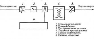
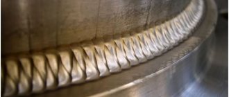
When choosing a welding machine, a dilemma arises: give preference to quality or price. The second, as a rule, wins. Cheaper “welders” are characterized by difficult arc ignition and metal spattering during welding due to current pulsations. The use of a choke in the welding machine circuit allows you to obtain a high-quality and even welding seam, simplifies ignition of the arc and its retention.
Principle of operation
The principle of operation of an electric choke is to restrain a sharp increase in current and smooth out the voltage drop line. How an electric choke works can be seen in the example of a fluorescent lamp. To prevent the gas in the flask from burning, but gradually warming up, the coil gradually brings the current to the nominal value.
The incoming current “wastes” its strength to induce a magnetic field around the coil. When the magnetic flux reaches its maximum, the current will begin to flow unhindered through the coil.
Important! Chokes are found in all electrical circuits. Smoothing the initial electrical voltage protects the radio and electrical components from critical overloads
Chokes with 2.8mm ferrite cores
Also, a miniature inductor can be made by winding a wire on a small-sized ferrite core 400N, 600N with a diameter of 2.8 mm and a length of approximately 12...14 mm. The form for calculating a choke on a 2.8mm core is given below.
Rice. 4. Homemade chokes on ferrite cores with a diameter of 2.8 mm.
Using the above forms for calculating inductors, you can easily calculate and make a homemade inductor for your radio-electronic device.
How does a transformer work?
Let's consider the operation of a choke assembled on a closed magnetic circuit and connected as a load to an alternating current source. The number of turns and the magnetic permeability of the core are selected in such a way that its reactance is high, but the current flowing in the circuit is correspondingly not.
The current, periodically changing its direction, will excite an electromagnetic field in the winding of the coil (let's call it coil number 1), the direction of which will also periodically change - reversing the magnetization of the core. If an additional coil is placed on the same core (let’s call it number 2), then under the influence of the alternating electromagnetic field of the core, an induced variable E.M.F. will appear in it.
If the number of turns of both coils is the same, then the value of the induced E.M.F. very close to the value of the voltage of the power source applied to coil number 1. If the number of turns of coil number 2 is halved, then the value of the induced E.M.F. will decrease by half, if the number of turns is the opposite, increase - the induced E.M.F. will also increase. It turns out that for each turn there is a certain part of the voltage.
The winding of the coil to which the supply voltage is applied (number 1) is called primary, and the winding from which the transformed voltage is removed is called secondary.
The ratio of the number of turns of the secondary (Np) and primary (Ns) windings is equal to the ratio of their corresponding voltages - Up (primary winding voltage) and Us (secondary winding voltage).
Thus, a device consisting of a closed magnetic circuit and two windings in an alternating current circuit can be used to change the supply voltage - transformation. Accordingly, it is called a transformer.
If you connect any load to the secondary winding, a current (Is) will arise in it. This will cause a proportional increase in current (Ip) in the primary winding. The following ratio will be correct:
Transformers can be used both for converting the supply voltage and for decoupling and matching amplification stages
When working with transformers, you need to pay attention to a number of important parameters, such as: 1. Permissible currents and voltages for the primary and secondary windings
2. The maximum power of the transformer is the power that can be transmitted through it for a long time without causing overheating of the windings. 3. Operating frequency range of the transformer.
Features of the AC choke
An AC choke, just like any other choke, is an inductor with a ferromagnetic core. This type of inductor is connected in series with the load, similar to a smoothing inductor, but unlike it, the current flowing through the AC inductor does not have a DC bias current. In this regard, the AC inductor is widely used in ballast and current-limiting circuits, powerful antenna and filter devices, as well as in various pulse voltage converters.
Regardless of the use of the inductor in the circuit, its operation is based on the dependence of its reactance XL on the frequency f of the current IH flowing through it and the voltage drop across the inductor UL
AC choke.
Thus, the voltage across the inductor UL is determined by the inductance of the inductor L and the parameters of the current flowing through the inductor: the frequency of the current f and the value of the current in the circuit IH.
Application area
Inductors are used as:
- current limiters;
- saturation coils;
- anti-aliasing filters;
- magnetic amplifiers (MU);
- resonant circuits;
- electronic choke in radio, - and computer circuits.
Current limiters
Why chokes are needed as current limiters can be found in the following list:
- Coreless coils have low resistance, so they effectively limit the amount of short circuit current. Even the slightest reduction in short circuit arc power is of great importance.
- When starting powerful electric motors, the inductors are switched on. After the device reaches maximum speed, the coil is turned off by the starting device.
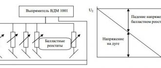
- In fluorescent lamps, electric chokes prevent the sudden switching on of maximum current. As a result, the mercury gradually warms up and passes into a vapor state. For DRL 250 lamps, the chokes are located inside the bulb. The chokes of the HPS lamps are located inside the casing separately from the bulb.
Note! The abbreviation DRL stands for Mercury Arc Lamp. HPS – Sodium Arc Tube
Saturation coils
After the magnetic field is saturated, the coil resistance stops increasing. Previously, saturation coils formed the basis of voltage stabilizers. Today they have been replaced by electronic systems.
Antialiasing filters
What is a throttle in electronics? These are smoothing filters that straighten the AC voltage ripple line. As a result, the stability of the electronic equipment is ensured. This filter looks like a barrel on a USB cable. Inside it is a single-turn coil. Electronic boards use chokes of the r68 brand.
Magnetic amplifiers (MU)
They were included in the electric motor control system. Magnetic induction in the core was saturated by magnetization of the core steel. The starter used several windings at once. Today, instead of magnetic starters, thyristor systems are used.
Magnetic starter circuit
Resonant circuits
A resonant circuit is used in tuners. An inductive coil in parallel with a capacitor is combined into a single system, which constitutes a resonant circuit. The circuit provides low resistance with a fixed frequency.
Principles for calculating AC chokes
The calculation of the AC choke is carried out similarly to the calculation of the smoothing choke, but taking into account the initial conditions. So for an AC inductor, the determining parameters are: the required inductance L, the applied voltage UL, the AC frequency f, the overheating of the inductor. In addition, it is necessary to determine the material of the inductor core, which will determine the saturation induction BS and the maximum induction in the core Bm, which, to prevent saturation of the core, is selected from the condition
Calculations of an AC inductor are based on expressions for determining the magnitude of the effective voltage dropped across the inductor UL
where f is the frequency of alternating current,
L – inductance of the inductor,
I – effective value of the inductor current.
Then, taking into account the expression for the inductance of a closed-core inductor and the expression for the maximum inductance in the core, the voltage on the inductor will depend on the following parameters
where μе is the equivalent magnetic permeability of the core,
μ0 – magnetic constant, μ0 = 4π•10-7 H/m,
ω – number of turns of the inductor winding,
Se – equivalent cross-section of the inductor core,
le is the equivalent length of the magnetic path of the inductor core,
Bm – maximum value of core magnetic induction,
ka is the current (voltage) amplitude coefficient of the inductor.
The resulting expression can often be found under the name of the basic formula of transformer EMF, since it establishes a unique relationship between the EMF at the winding terminals and the number of turns of the winding, for a given value of magnetic induction in the core. Then, with a sinusoidal voltage (amplitude factor ka ≈ 1.414), the expression takes the following form
Let's return to the original expression for the voltage on the inductor UL, in which the parameter - the number of turns - is ambiguous. This parameter, among other things (the magnitude of inductance L and magnetic permeability μe of the core) depends on the dimensions of the magnetic circuit, and more specifically on the area of the window SO, which can be calculated using the following expression
where I is the effective value of the inductor current,
ω – number of turns of the inductor winding,
kI – core window utilization factor,
j is the current density in the winding wire.
The parameters kI and j are chosen in the same way as for the smoothing filter choke, that is, the core window utilization factor kI ≈ 0.3, and the current density j = 5 A/mm2.
Then, expressing from this expression the number of turns of wire ω, we obtain
The resulting expression determines the main calculation expression for determining the standard size of the core - the product of the areas of the SeSO core. After transforming the expression for the effective voltage on the inductor UL, we determine the number of turns of the winding ω and the value of the non-magnetic gap δ
where μе is the equivalent magnetic permeability of the core,
μ0 – magnetic constant, μ0 = 4π•10-7 H/m,
Se – equivalent cross-section of the inductor core,
le is the equivalent length of the magnetic path of the inductor core,
Bm – maximum value of core magnetic induction,
ka is the current (voltage) amplitude coefficient of the inductor.
The calculated number of turns is approximate, since due to the broadening of the magnetic flux, the inductance value turns out to be slightly larger for a given number of turns, which in some cases is undesirable. Therefore, it is necessary to recalculate the turns taking into account the magnetic flux broadening coefficient F
It remains to select the cross-section of the winding wire SP
where SO is the window area of the core used,
kI – core window utilization factor,
ω – number of turns of the inductor winding.
The choice of wire cross-section must be made by rounding the resulting value to the nearest nominal value, while it must be taken into account that at high frequencies power losses in the wire increase. Therefore, at a sufficiently high frequency, it is necessary to use a winding wire consisting of several cores, and the core diameter is selected based on the skin depth δ
where f is the frequency of the alternating current flowing through the inductor,
δ – skin layer thickness,
dп – diameter of the core in the winding wire.
After constructive calculation of the core and winding, it is necessary to check the thermal operating conditions of the inductor - heating and overheating of the inductor.