Basic technological operations of sheet stamping
All technological operations of sheet stamping are divided into two groups. The first group includes operations in which the workpiece is brought to destruction during the deformation process. These operations are usually called separation operations
. The second group includes form-changing operations, in which deformation of the workpiece should not be accompanied by destruction.
During technological operations that ensure a given form change, plastic deformations occur only in a part of the workpiece, which is called the deformation zone. When performing separation operations, one strives for maximum localization of the source of deformation in order to reduce distortions during deformation and quickly exhaust the plasticity resource. When performing form-changing operations, the size of the deformation zone is increased in order to reduce the likelihood of destruction.
In the classical form, stamping operations are performed using two working tools - a punch and a matrix. Punch
is called a tool that covers the workpiece, and
a matrix
is a tool that covers the workpiece during the deformation process. The punch and die can be solid, elastic, liquid, gaseous or electromagnetic.
The degree of localization of the source of deformation depends on the dimensional characteristics of the tool, in particular on the gap between the punch and the matrix, as well as on the radii of curvature of the working edges of these tools. The smaller the gap and the radii of curvature of the working edges, the more localized the source of deformation is in the workpiece.
For separation operations, the working edges must be sharp, and the gap between the punch and the matrix must be tenths or even hundredths of the workpiece thickness. For forming operations, the radii of rounding of the edges of the tools significantly exceed the thickness s of the workpiece, and the gaps are usually somewhat larger than its thickness.
To carry out sheet metal stamping, the following equipment is used: shears (guillotine, disk, vibration, etc.), presses (crank, hydraulic), sheet metal stamping hammer and installations for special stamping methods (rotary drawing, explosion stamping, electromagnetic, electro-hydraulic stamping, etc. ). Sheet stamping processes consist of separating and forming operations performed in a certain sequence, through which the original workpieces are given the required shape and dimensions.
Separation operations (cutting, cutting, punching) are accompanied by the destruction of the workpiece along certain surfaces.
Segment
- this is the separation of part of the workpiece along an open contour using scissors or stamps. It is usually used as a procurement operation for dividing sheets into strips and blanks of given sizes for subsequent stamping.
The quality of the cut surface provides the required gap between the cutting edges, which is z = (0.03...0.1)s.
Cutting and punching
involve separation of the workpiece along a closed contour in the die. The outer contour of the product is formed with a cutting punch, and the inner contour (hole) with a punching punch. When cutting down, the separated part is a product, and when punching, on the contrary, it is waste. The nature of the workpiece deformation during cutting and punching is the same. At a certain depth of penetration of the cutting edges (the greater, the higher the plasticity of the metal), cracks appear in the workpiece with an inclination angle of 4...6° to the tool axis. A zone of hardened metal is formed near the cut surface. This makes subsequent stamping of the cut-out blanks difficult. To improve the quality of the surface and the perpendicularity of the cut, finishing cutting is used, the essence of which is to create all-round compression in the zone of the source of plastic deformation. When punching with compression, the gap between the punch and the matrix is set equal to 0.005...0.01 mm, i.e., significantly smaller than during a conventional separation operation. Compression punching can be combined with hole punching, which in some cases reduces the amount of machining required to produce parts. Finish cutting is used to produce flat cams, gears, permanent magnet plates, etc.
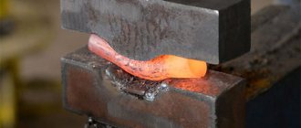
Form-changing operations - bending, drawing, flanging, crimping, expansion, molding - are performed by plastic deformation of the metal without destroying the workpiece (Fig. 26.8).
Bending
- a change in the curvature of the middle surface with its almost unchanged linear dimensions - is accompanied by an uneven distribution of deformation across the thickness (Fig. 26.8, a). When bending, only the part of the workpiece in the contact zone with the punch is plastically deformed: the outer layers are stretched, and the inner layers (facing the punch) are compressed.
As the radius of curvature of the punch decreases, the likelihood of cracks forming, propagating from the outer surface into the thickness of the workpiece, increases. Therefore, to prevent the destruction of the workpiece during deformation, the minimum bending radius must exceed rmin > (0.1...2.0) s.
Hood
- an operation by which hollow spatial products are obtained from a flat workpiece (Fig. 26.8, b). Under the influence of the punch, a flat workpiece with a diameter Dzag is drawn into the hole of the matrix and takes the shape of a hollow product with a diameter d. The shape change of the workpiece during drawing is assessed by the degree of drawing K = Dzag/d, the value of which, depending on the mechanical properties of the material and drawing conditions, should not exceed 1.8...2.1 per transition.
Products with a large change in the shape of the workpiece are obtained through several drawing operations with a gradual decrease in the diameter of the hollow workpiece and an increase in its height (Fig. 26.8, c).
During subsequent transitions, the value of K becomes 1.2...1.4. Intermediate annealing to eliminate work hardening allows you to increase the drawing ratio to 1.4...1.6. The danger of workpiece destruction is also eliminated by rounding the edges of punches and dies with a radius r = (5...10)s and using lubricants to reduce the friction forces between the surfaces of the workpieces and the tool. Beading
- the operation of obtaining a side (neck) in a flat or spatial workpiece by pressing a part of the workpiece with a pre-punched hole into the hole of the matrix (Fig. 26.8, d). The permissible form change without destruction is characterized by the flanging coefficient K0 = db/d0, where db is the diameter of the bead; do is the diameter of the hole in the flat workpiece. The Ko coefficient depends on the mechanical properties of the workpiece and its relative thickness s/d0 and is usually 1.2...1.8.
Crimping
- an operation designed to reduce the transverse dimensions of the edge part of a hollow cylindrical workpiece by pushing it into the narrowing cavity of the matrix (Fig. 26.8, c)). The permissible change in shape during crimping is limited not by the destruction of the workpiece, but by the loss of its stability during the deformation process. The main type of loss of stability is the formation of folds. In this case, the formation of an annular fold in the cylindrical undeformed part of the workpiece or longitudinal folds in the deformation zone is possible. Usually, in one transition it is possible to obtain a product with a diameter of the edge section d = (0.7...0.8) Dzag. Wrinkles are eliminated by supporting the walls of the workpiece.
Molding
- the operation of obtaining local depressions and bulges in sheet and spatial blanks (Fig. 26.8, f). During forming, the deformation zone covers the part of the workpiece opposing the matrix cavity. The stress state scheme is close to the biaxial tension scheme, and shaping is carried out due to the thinning of the workpiece. The height h of the resulting depression is limited by the possibility of destruction of the workpiece in places of greatest thinning and significantly depends on the mechanical characteristics of the deformed material.
The permissible value of h increases with increasing thickness of the workpiece, all other things being equal. Molding is used to produce membranes with annular corrugations, stiffeners in shells, as well as for the manufacture of products of complex asymmetrical shapes.
With high-speed stamping methods, the speed of movement of the workpiece reaches 300...400 m/s. Under these conditions, the ductility of carbon and alloy structural steels, as well as ductile alloys of non-ferrous metals, increases significantly, due to which their permissible deformation increases. However, in hard-to-deform alloys, an increase in ductility is not observed. In industry, the following methods of high-speed deformation are most widely used: explosive stamping, electrohydraulic and electromagnetic stamping.
Drawing
Sheet stamping - a method of manufacturing flat and three-dimensional thin-walled products from sheet material, tape or strip using stamps on presses or without the use of presses. Sheet stamping is divided into hot and cold.Hot stamping. It is mainly used in the production of boiler bottoms, hemispheres, buoys and other hull parts for shipbuilding. They are made from steel sheet with a thickness of 3 ... 4 mm. Hot sheet metal stamping operations are similar to cold stamping operations. However, when designing a technological process, heating is always taken into account. When drawing up a drawing of a workpiece, it is necessary to take into account the shrinkage of the metal during cutting, punching and bending, as well as the degree of warping when the part cools, since its dimensions are somewhat reduced. This circumstance forces us to increase dimensional tolerances in comparison with cold stamping. Workpieces are heated in flame and electric furnaces, as well as in electric heating devices.
Cold stamping . This is the most progressive method of pressure processing, since it allows you to obtain parts that in most cases do not require further cutting. Cold sheet stamping is used to produce both large and small parts (car frames and bodies, aircraft chassis, ship trim elements, watch mechanism parts, etc.).
Sheet stamping allows for greater savings in metal usage while at the same time providing high productivity. But it gives the greatest effect in mass and large-scale production.
Cold sheet stamping uses carbon and alloy steel, aluminum and its alloys, copper and its alloys, as well as non-metallic materials: cardboard, hard rubber, leather, rubber, fiber, plastic, supplied in the form of sheets, tapes and strips.
Sheet stamping technology. The main technological equipment for the manufacture of products by sheet stamping are vibrating shears (Fig. 77), crank presses (see Fig. 87 and Fig. 88) and hydraulic presses. Sheet stamping operations can be divided into two main types: parting and forming. The main separating operations include: cutting, punching and punching.
Rice. 77
Rice. 87
Rice. 88
Cutting is an operation where sequential separation of part of the workpiece occurs along a straight or curved line. Cutting is used to obtain both finished parts and cutting the sheet into strips of the required width. When cutting a sheet, it is necessary that the output of parts from the sheet is maximum and waste is minimal. The rationality of cutting is determined based on the calculation of the material utilization rate. The coefficient is understood as the ratio of the area of the cut parts to the area of the sheet. The cutting operation is carried out using vibrating, disk, guillotine and other shears.
Vibrating shears (Fig. 77) are a machine with short knives. The upper knife 5 receives oscillatory movements from the electric motor 1 through an eccentric mechanism. The sheet metal is installed on the table 7 and moved between the upper 5 and lower 6 knives until it stops 3, which can be moved and secured in the frame bracket, 2.4 - the head, 8 - the bed stand.
Cutting is an operation to obtain a closed-loop blank (Fig. 78). In Fig. 79 shows drawing (I) and diagram (II) of a typical part made from strip by cutting.
Rice. 78
Rice. 79
Punching - making holes in a part of the desired shape (Fig. 80).
Rice. 80
The main forming operations* include bending, drawing, flanging, crimping and forming.
Bending is an operation in which a flat workpiece is given a curved shape (Fig. 81: 1 - punch; 2 - neutral layer; 3 - matrix): R and r - outer and inner bending radii, S - thickness of the material. It can be V-shaped, U-shaped, etc. (Fig. 82).
Rice. 81
Rice. 82
In Fig. 83 shows a drawing of a part in which the holes are made by punching. After this, the part is bent on the die.
Rice. 83
Drawing is an operation that turns a flat workpiece into a hollow spatial part or semi-finished product 2 (Fig. 84). The hood is used to produce not only cylindrical parts, but also complex-shaped box-shaped, conical and hemispherical ones. When drawing, the flat workpiece 5 is pulled by the punch 1 into the hole of the matrix 3. To prevent the formation of folds in the workpiece under compressive stress, clamps 4 are used.
Rice. 84
The hood can be without thinning or with thinning. In the first case, it occurs without a noticeable change, in the second, not only the shape of the workpiece changes, but also the thickness of its walls. In the case when it is necessary to obtain a deep drawing, it is carried out in several passes. In Fig. 85 shows a drawing of a typical part made from metal sheet 1, made by stamping with drawing.
Rice. 85
Beading is the operation of forming edges along the outer contour of a sheet blank or around pre-punched holes (Fig. 86). It is used mainly for the formation of necks in flat parts 2, necessary both for threading and welding or assembly. Usually it is performed sequentially (I, II, III) in one or several passes in dies consisting of punch 1 and matrix 3. The flanging operation is very often performed at the ends of pipes when connecting flanges to them, with the help of which the pipes will be connected in the future.
Rice. 86
Crimping is an operation of narrowing (reducing) the end part of hollow or three-dimensional parts. It is carried out by compressing the material with a stamp from the outside in a conical matrix. In this case, the configuration of the crimped part depends entirely on the shape of the die.
Molding is an operation associated with a local change in shape while maintaining the configuration of the outer contour of the part. An example of molding is the production of stiffeners on engineering parts, as well as an increase in the diameter of the middle part of a hollow part.
The technological process of processing various materials by pressure, as mentioned above, is carried out on presses. Presses are hydraulic and mechanical (crank, screw, rack and pinion, etc.). According to their purpose, presses are divided into forging, stamping, sheet-stamping, embossing, trimming, pipe-shaping, bending, straightening, briquetting (for the production of briquettes from lumpy or powdery materials), forging and stamping machines, thermoplastic machines, etc.
Crank hot stamping presses GOST 6809-87E (Fig. 87) are manufactured in Russia with pressures from 61.78 to 617.8 kN (mc is a unit of force and weight). They consist of a frame 1, a slider 2, a connecting rod 3, a crank shaft 4, 5 service columns, a gear 6 and a friction clutch 7. The use of presses for hot die forging is very effective in comparison with other technological equipment. They provide higher precision forgings with significant metal savings. The presence of induction electric heating in them helps to improve working conditions in the workshop: noise and shaking of the building are reduced, and smoke in production premises is eliminated. The press is controlled by regulatory bodies and with the help of compressed air from the workshop line.
Rice. 87
In Fig. Figure 88 shows a press for cold stamping GOST 9408-89E, consisting of a rack 1, an electric motor 2, a slider balancing cylinder 3, a gear 4, guides 5, a slider 6 and a press table 7. Both small and large sheet parts are produced on such presses , for example, car bodies. Possible press pressure is 30.89 kN.
Rice. 88
Hydraulic presses have the best characteristics for deep drawing and other sheet metal stamping operations, since they deform the metal at a constant speed. Such presses are widely used in the aviation and rocket industries.
In Fig. 89 and 90 show large aircraft assembly units, the parts of which are made by pressing. Thus, the floor frame of an aircraft passenger cabin (Fig. 89) includes: skin 1, frame 2, stringers 3, transverse beams 4 and continuous beams 5. And the nacelle of an aircraft turboprop engine (Fig. 90) consists of a propeller hub fairing - 1 , air intake 2, front hood cover 3, rear hood cover 4, hatch 5, power truss, casing 7, stacker 8, tail part of the nacelle 9, power frame 10, oil cooler frame 11, power frame 12 and side beam 13.
Rice. 89
Rice. 90
Progressive methods of cold sheet stamping. New types of stamping, due to their simplicity and efficiency, are widely used in small-scale and single-piece production. These include stamping with rubber, liquid, explosion, electro-hydraulic, etc.
Rubber stamping . With its help, separation and form-changing operations are carried out. In this case, the punch or matrix is rubber. Rubber stamping is most often used for products made of thin sheet metal up to 2 mm thick (aluminum, copper alloys, low-carbon steel).
Liquid stamping. In this case, the metal is deformed under fluid pressure, taking the form of a matrix. This method is used for drawing hollow parts of various shapes.
Explosion stamping . To plastically change the shape of a workpiece, explosives are also used (explosive gas mixtures of methane, propane, hydroxygen, etc.), creating high pressure, under the influence of which the workpiece takes the shape of a stamp.
Explosion stamping is used for the manufacture of large parts and parts of complex shapes, when their manufacture by other methods is impossible (for example, hard-to-deform alloys) or uneconomical. Such
stamping does not require complex and expensive equipment.
Electrohydraulic stamping . This method is characterized by the fact that the energy carrier is a high-voltage electric charge in the liquid. The discharge causes the appearance of a shock wave, which deforms the workpiece, giving it the required shape.
This type of stamping makes it possible to perform all cold sheet stamping operations with great accuracy and at relatively low cost.
Magnetic pulse molding. The formation of products by this method occurs when a pulsed magnetic field is created around the workpiece and the interaction of this field with pulsed currents flowing in the workpiece. As a result of this interaction, eddy currents are excited in the workpiece, which also leads to the formation of an electromagnetic field around it. This creates the prerequisites for a dynamic effect on the workpiece and its deformation.
This method is used to perform compression of pipe blanks, relief molding, cutting, etc.
There are other progressive methods of sheet stamping, but we will not consider them.
* Shaping operations are those by which spatially shaped parts are obtained from a flat workpiece
Features of the technology
You can familiarize yourself with the GOST requirements for metal stamping processing by downloading the document in pdf format from the link below.
GOST 18970-84 Metal forming. Forging and stamping operations. Terms and Definitions
In addition to the division into hot and cold, stamping of metal products is also divided into a number of other categories depending on its purpose and technological conditions. Thus, stamping operations, as a result of which a part of the metal workpiece is separated, are called separation operations. This, in particular, includes cutting, chopping and punching metal parts.
Another category of such operations, as a result of which the stamped sheet of metal changes its shape, is form-changing stamping operations, often called forming. As a result of their implementation, metal parts can be subjected to drawing, cold extrusion, bending and other processing procedures.
Schemes and types of extrusion (pressing)
As noted above, there are types of stamping, such as cold and hot, which, although implemented according to the same principle, which involves deformation of the metal, have a number of significant differences. Stamping of parts, which involves preheating them to a certain temperature, is used mainly in large manufacturing enterprises.
This is primarily due to the rather high complexity of such a technological operation, for the high-quality implementation of which it is necessary to make a preliminary calculation and accurately observe the degree of heating of the workpiece being processed. Using hot stamping, sheet metal of various thicknesses is used to produce critical parts such as boiler bottoms and other hemispherical products, hulls and other elements used in shipbuilding.
Characteristics and types of parts produced on hot stamping presses
To heat metal parts before hot stamping, heating equipment is used, which is able to provide precise temperature conditions. Electrical, plasma and other heating devices may be used in particular for this function. Before starting hot stamping, it is necessary not only to calculate the heating rates of the parts being processed, but also to develop an accurate and detailed drawing of the finished product, which will take into account the shrinkage of the cooling metal.
When performing cold stamping of metal parts, the process of forming the finished product occurs only due to the pressure exerted by the working elements of the press on the workpiece. Due to the fact that the blanks are not preheated during cold stamping, they are not subject to shrinkage. This allows us to produce finished products that do not require further mechanical modification. That is why this technology is considered not only a more convenient, but also a cost-effective processing option.
Cold stamping is used to process sheet metal up to 10 mm thick
If you skillfully approach the issues of designing the size and shape of workpieces and the subsequent cutting of the material, you can significantly reduce its consumption, which is especially important for enterprises that produce their products in large batches. The material from which workpieces are successfully stamped can be not only carbon or alloy steels, but also aluminum and copper alloys. Moreover, an appropriately equipped stamping press is successfully used for processing workpieces made of materials such as rubber, leather, cardboard, and polymer alloys.
Separation stamping, the purpose of which is to separate a part of the metal from the workpiece being processed, is a very common technological operation used in almost every manufacturing enterprise. Such operations, which are performed using a special tool mounted on a stamping press, include cutting, punching and punching.
This press is equipped with special plungers for punching holes in the workpiece
During the cutting process, metal parts are separated into separate parts, and such separation can be carried out along a straight or curved cutting line. Various devices can be used to perform cutting: disc and vibrating machines, guillotine shears, etc. Cutting is most often used to cut metal workpieces for further processing.
Punching is a technological operation during which parts with a closed contour are obtained from a metal sheet. Using punching, holes of various configurations are made in sheet metal blanks. Each of these technological operations must be carefully planned and prepared so that the result is a high-quality finished product. In particular, the geometric parameters of the tool used must be accurately calculated.
Perforated metal sheet is obtained by cutting holes on a jig punch press
Technological stamping operations, during which the initial configuration of metal parts is changed, are forming, bending, drawing, flanging and crimping. Bending is the most common form-changing operation, during which bending areas are formed on the surface of a metal workpiece.
Drawing is a volumetric stamping, the purpose of which is to obtain a volumetric product from a flat metal part. It is with the help of drawing that a metal sheet is transformed into products of a cylindrical, conical, hemispherical or box-shaped configuration.
Along the contour of sheet metal products, as well as around the holes that are made in them, it is often necessary to form a side. Flanging successfully copes with this task. The ends of the pipes on which flanges need to be installed are also subjected to this treatment, performed using a special tool.
Flanging can be done in various ways
With the help of crimping, unlike flanging, the ends of pipes or the edges of cavities in sheet metal blanks are not expanded, but narrowed. When performing such an operation, carried out using a special conical matrix, external compression of the sheet metal occurs. Molding, which is also one of the types of stamping, involves changing the shape of individual elements of a stamped part, while the outer contour of the part remains unchanged.
Volumetric stamping, which can be performed using various technologies, requires not only careful preliminary calculations and the development of complex drawings, but also the use of specially manufactured equipment, so implementing such technology at home is problematic.
mtomd.info
Separating operations are intended either to obtain a workpiece from a sheet or strip, or to separate one part of the workpiece from another. Operations can be performed along a closed or open loop. The separation of one part of the workpiece from another is carried out by a relative displacement of these parts in a direction perpendicular to the plane of the workpiece. This displacement is initially characterized by plastic deformation and ends with destruction.
Cold stamping Sheet stamping. Cold sheet stamping. Sheet metal stamping. Form-forming operations of sheet stamping. Flexible. Hood. Beading. Crimping Distribution. Relief molding.
Cutting off is the separation of part of a workpiece along an open contour using special machines - scissors or stamps. It is usually used as a procurement operation for dividing sheets into strips and blanks of the required size.
Figure 1 - Basic types of scissors
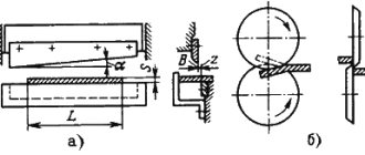
a – guillotine;
b - disk shears with translational movement of the cutting edges of the knife can be with parallel knives, for cutting narrow strips, with one inclined knife - guillotine (Fig. 1, position a). The cutting edges in guillotine shears are inclined to each other at an angle of 1...5o to reduce the cutting force. The sheet is fed until it stops, which determines the width of the cut strip B. The length of the cut strip L should not exceed the length of the knives.
Scissors with rotational movement of the cutting edges are disk scissors (Fig. 1, position b). The length of the cut piece is not limited by the tool. The rotation of the disc knives not only ensures separation, but also feeds the workpiece under the influence of friction forces. The cutting edges of the knives overlap one another, this ensures the straightness of the cutting line. To ensure gripping and feeding of the workpiece, the diameter of the knives must be 30...70 times greater than the thickness of the workpiece, increasing as the friction coefficient decreases.
Cold forming of metals
Cutting and punching is the separation of metal along a closed contour in a die. When cutting and punching, the nature of the workpiece deformation is the same. These operations differ only in purpose. The outer contour of the part is formed by cutting, and the inner contour is formed by punching (making holes).
The main technological parameter of the operations is the radial gap between the punch and the matrix Z. The gap Z is assigned depending on the thickness (s) and mechanical properties of the workpiece; it is approximately (0.05..0.1)s. When punching, the dimensions of the die hole are equal to the dimensions of the product, and the dimensions of the punch are 2Z smaller than them. When punching, the size of the punch is equal to the dimensions of the hole, and the dimensions of the matrix are 2Z larger than them.
Figure 2 - Schemes of cutting and punching processes
a - cutting down; b - punching
1 – punch; 2 – matrix; 3 – product; 4 – departure
Reducing the cutting force is achieved by making a bevel on the matrix when cutting, and on the punch when punching.
When stamping small and medium-sized parts, several flat blanks are cut out from one sheet blank for stamping. Between the adjacent contours of the cut-out workpieces, jumpers are left with a width approximately equal to the thickness of the workpiece. In some cases, adjacent workpieces are cut out without jumpers (saving metal while deteriorating the quality of the cut and reducing tool life).
The arrangement of the contours of adjacent cut-out blanks on sheet material is called cutting. The part of the workpiece remaining after cutting is cutting . Die cutting constitutes the main waste in sheet metal stamping. The type of cutting should be selected based on the condition of reducing metal waste in the die cutting.
Figure 3 - Metal cutting
a - with jumpers; b - without jumpers
Cold stamping Sheet stamping. Cold sheet stamping. Sheet metal stamping. Form-forming operations of sheet stamping. Flexible. Hood. Beading. Crimping Distribution. Relief molding.
Metal savings can be achieved by: reducing metal consumption for jumpers, using waste-free and low-waste cutting, increasing the accuracy of calculating the dimensions of the workpiece and reducing allowances for cutting.
Lecture 12. Cold stamping
Lecture 12. Cold stamping
Cold stamping is called stamping without heating the workpieces. It is divided into volumetric and sheet.
1. Cold die forging (CDF)
Cold die forging makes it possible to almost completely eliminate cutting processing. The main types of cold die forging: extrusion, upsetting, die-casting and calibration (embossing). Cold extrusion is similar to pressing, and cold heading, die forming and sizing are similar to the corresponding hot die forming processes. But they ensure the achievement of greater accuracy and better surface quality of parts (surface roughness 0.4 microns, tolerances 0.02–0.05 mm).
Rod material made of carbon, alloy steels, non-ferrous metals and their alloys, which have the necessary ductility in a cold state, is most often used as workpieces for cold steel. Preparation of the workpiece surface is of great importance: removal of contaminants, surface defects, etc.
Stamping is carried out in the same dies that are used for hot processing.
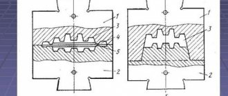
Extrusion
Extrusion
– formation of a workpiece by plastic flow of material in the die cavity.
There are direct, reverse, lateral and combined extrusion.
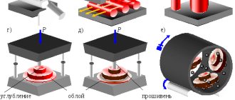
Fig.1. Extrusion patterns
With direct
When extruding, the metal flows from the matrix in a direction coinciding with the direction of movement of the punch (Fig. 1a, b). Using this method, you can obtain parts such as a rod with a thickening, tubes with a flange, glasses with a flange.
In case of reverse
During extrusion, the metal flows in the direction opposite to the direction of movement of the punch, into the annular gap between the punch and the die to produce hollow parts with a bottom (Fig. 1c).
With lateral
During extrusion, the metal flows into the side holes of the matrix at an angle to the direction of movement of the punch (Fig. 1d). In this way, parts such as tees, crosses, etc. can be obtained.
With combined
During extrusion, metal flows in several directions (Fig. 1d). Combinations of different schemes are possible.
Plastic deformation by extrusion occurs under conditions of uneven all-round compression and provides a high degree of deformation.
Due to the high cost of dies, extrusion is advisable to use in large-scale and mass production.
Cold landing
Disembarkation
– formation of local thickenings of the required shape on the workpiece as a result of upsetting of its end. Used in the manufacture of a wide range of parts in mass production: bolts, screws, nuts, rivets, nails, spokes, etc.
The starting material is wire or rods. Landing is carried out using cold disembarkation machines
.
In the first transition, the rollers 2 feed the rod 1 to the stop 4, after which the matrix 3 moves to the landing position, cutting off the measured workpiece from the rod.
In the second transition, the head is upset by hitting the landing punch 5. After the punch returns to its original position, the rivet is pushed out by pusher 6, which also returns to its original position, and the matrix again goes to the feed line.
The number of upsetting transitions is calculated mainly based on the ratio of the length of the upsetting part and the diameter of the workpiece, which characterizes the resistance to longitudinal bending. At use one transition, at – two transitions, at – three transitions. With a large number of transitions, the metal becomes stronger, so annealing is required.
The productivity of the machines reaches 400 products per minute. Compared to manufacturing by cutting, upsetting provides up to 30–40% metal savings.
2. Sheet stamping
Sheet stamping
– a method of manufacturing flat and three-dimensional thin-walled products from workpieces in the form of tape, strip, roll.
It is characterized by high productivity, stability of quality and accuracy, low cost of manufactured parts, and the possibility of full automation. Sheet stamping capacity is up to 40 thousand parts per shift.
The thickness of the workpiece during sheet stamping is usually no more than 10 mm, but sometimes it can exceed 20 mm; in this case, stamping is carried out with preheating to forging temperatures.
When sheet stamping is used: low-carbon steels, ductile alloy steels, non-ferrous metals and alloys based on them, precious metals, as well as non-metallic materials: organic glass, felt, celluloid, textolite, felt, etc. Bimetallic and multilayer sheets are also used.
Sheet stamping operations are divided into separation and form-changing operations.
In separation operations, the stage of plastic deformation of the material necessarily ends with its destruction. Separation operations include:
1. Segment
– complete separation of part of the workpiece along an open contour by shearing. Cutting is carried out using scissors with parallel knives, with inclined knives (guillotine), using circular knives, using cutting dies.
Fig.2. Cutting schemes: a) inclined knives b) circular knives
In scissors with linear movement of knives (Fig. 2a), a slider with an upper knife mounted on it moves up and down in the side guides of the frame; the lower knife is fixedly fixed in the frame. The raising and lowering of the upper knife is carried out by a crank mechanism. The sheet to be cut is placed on the scissors table and pressed against it using pneumatic or hydraulic clamps. In guillotine shears, the cutting edges of the knives, in order to reduce the cutting force, are inclined to each other at an angle of 1–5°. The sheet is fed until it stops, which determines the width of the cut strip B
. The length of the cut strip L should not exceed the length of the knives.
The cutting force is determined by the formulas:
-for scissors with parallel knives
-for guillotine shears
where in
– length of the cutting line, mm;
S
– material thickness, mm; – shear resistance equal to 0.8–0.9 of the ultimate strength of the material; – bevel angle of the upper knife.
Scissors with rotational movement of the cutting edges are disk scissors (Fig. 2b). They are used for cutting sheet strips of unlimited length, as well as for cutting along a curved contour. The rotation of the disc knives not only ensures separation, but also feeds the workpiece under the influence of friction forces. The cutting edges of the knives overlap one another, this ensures the straightness of the cutting line. To ensure gripping and feeding of the workpiece, the diameter of the knives must be 30...70 times greater than the thickness of the workpiece, increasing as the friction coefficient decreases.
2. Felling
– separation of part of the workpiece along a closed contour, with the separated part being the product.
Punching
– separation of part of the workpiece along a closed loop, with the separated part being waste.
The main technological parameter of the operations is the radial gap between the punch and the matrix. The gap is assigned depending on the thickness and mechanical properties of the workpiece; it is approximately . The gap during cutting is determined by reducing the cross-sectional dimensions of the punch, and when punching - by increasing the hole in the matrix.
Fig.3 Scheme of the cutting (a) and punching (b) processes
1 – punch, 2 – matrix, 3 – product, 4 – waste
When stamping, there are few and medium-sized parts, several flat blanks are cut out from one sheet blank for stamping. Between the adjacent contours of the cut-out workpieces, jumpers are left with a width approximately equal to the thickness of the workpiece. In some cases, adjacent workpieces are cut out without jumpers (saving metal while deteriorating the quality of the cut and reducing tool life).
The arrangement of the contours of adjacent cut-out blanks on sheet material is called cutting
.
The part of the workpiece remaining after cutting is cutting.
Die cutting constitutes the main waste in sheet metal stamping. The type of cutting should be selected based on the condition of reducing metal waste in the die cutting (Fig. 4).
Fig.4. Examples of cutting material with jumpers (a) and without jumpers (b)
Metal savings can be achieved by: reducing metal consumption for jumpers, using waste-free and low-waste cutting, increasing the accuracy of calculating the dimensions of the workpiece and reducing allowances for cutting.
The force of cutting or punching is determined by the formulas:
- for a round contour;
- for an arbitrary contour,
where: L
– length of the cutting line or cutting perimeter;
S
– thickness of the workpiece;
d
– diameter of the cut hole; – shear resistance.
Form-changing operations are operations by which a flat workpiece is transformed into a spatial part of the required shape without changing the thickness of the material. Basic forming operations: bending, drawing, flanging, crimping, spreading, relief molding.
1. Bending
– formation or change of angles between parts of the workpiece or giving it a curved shape. Bending is carried out in dies, as well as with rotating shaped rollers, which act as a matrix, on profile bending mills.
Fig.5. Bending scheme
1 – matrix, 2 – workpiece, 3 – punch, – bending angle, NN
– neutral layer,
R
– rounding radius
In places of bending, the outer layers of the workpiece are stretched, and the inner layers are compressed. Between them there is a neutral layer NN
, experiencing neither tension nor compression. The expanded length of the neutral layer determines the size of the workpiece before bending.
Bending is carried out as a result of elastoplastic deformation. in which, along with plastic, significant elastic deformation of the metal occurs. Therefore, after bending, the stretched and compressed layers of metal tend to return to their original position. As a result, the shape of the part after bending will not correspond to the shape of the stamp by the magnitude of the springback angle, which must be taken into account when manufacturing the tool. The spring angle is 1–8o.
With a decrease in the radius of rounding of the punch R, the probability of the formation of cracks extending from the outer surface into the thickness of the workpiece increases, therefore, depending on the plasticity of the metal.
The bending force is determined by the formula:
,
where in
– width of the workpiece,
S
– thickness of the metal.
2. Hood
– formation of a hollow product from a flat or hollow workpiece. The drawing is carried out in drawing dies on a crank press (Fig. 6).
The cut-out workpiece with a diameter is placed on the plane of the matrix. The punch presses on the workpiece, and it, moving into the hole of the matrix, forms the walls of the elongated part. Diameter of the drawn product.
Fig.6. Hood diagram
Shape change during drawing is assessed by drawing coefficient, which, depending on the mechanical characteristics of the metal and drawing conditions, should not exceed 1.8–2.1.
If this occurs, the flange may lose stability and wrinkles may form during stretching. They are prevented by pressing the workpiece flange against the die with a certain force. The clamping pressure is 1–3 MPa. The risk of workpiece destruction is also eliminated by rounding the edges of punches and dies and using properly selected lubricants to reduce the friction forces between the surfaces of the workpiece and the tool.
There are hoods without wall thinning and with wall thinning. Hood without wall thinning
obtain a hollow part from a sheet without changing its thickness.
This is achieved by taking the gap between the punch and the matrix equal to . When drawing with wall thinning
, in which the length of the hollow part increases due to the thinning of the side walls. The permissible reduction in wall thickness in one pass is 40–60%.
Parts with a large change in the shape of the workpiece are obtained through several drawing operations with a gradual decrease in the diameter of the hollow part and an increase in its height. On subsequent transitions.
Intermediate annealing to eliminate work hardening allows the EF to be increased to 1.4-1.6.
3. Beading
– formation of a side (neck) around a hole in the workpiece.
Fig.7. Flanging scheme
1–product; 2–blank; 3–punch; 4–matrix
The operation is characterized by the flanging coefficient
,
Where; d O
– hole diameter in a flat workpiece.
To avoid the formation of longitudinal cracks, it is necessary that KO
= 1.2–1.8. When flanging small holes, they strive to combine flanging with punching.
Flanging is used for the manufacture of ring parts with flanges and for the formation of ledges in parts for threading, welding or assembly, as well as to increase the rigidity of the structure while keeping its weight low.
4. Crimping
– reduction of the cross-sectional perimeter of the end part of the hollow workpiece.
Fig.8. Crimping diagram
It is performed by pushing the workpiece into the tapering cavity of the matrix (Fig. 8).
The operation is characterized by a crimp coefficient. To avoid the formation of longitudinal folds in the crimped part, it is necessary that the KO
=1.2–1.4. For greater shaping, several successive crimping operations are performed.
5. Giveaway
– increase in the perimeter of the cross section of the end part of the hollow workpiece. Dispensing is the opposite operation to crimping.
Tools and equipment for sheet metal stamping
Stamps are used as a tool for sheet stamping. Based on technological characteristics, dies of simple, sequential and combined action are distinguished. Stamps of simple action are single-operational, stamps of sequential and combined action are multi-operational.
In a simple action stamp
One operation is performed per stroke of the slider.
In a sequential action stamp
During one stroke of the slide, two or more operations are performed simultaneously in different positions, and the workpiece is moved by a feed step after each stroke of the press.
In a combined action stamp
in one stroke of the press slide, two or more operations are performed in one position without moving the workpieces in the feed direction.
Cold sheet stamping is carried out mainly on crank presses. For large-sized products made from thick sheets, hydraulic presses are used.