Sheet forming operations
Separation operations
are intended either for obtaining a workpiece from a sheet or tape, or for separating one part of the workpiece from another. Operations can be performed along a closed or open loop.
The separation of one part of the workpiece from another is carried out by a relative displacement of these parts in a direction perpendicular to the plane of the workpiece. This displacement is initially characterized by plastic deformation and ends with destruction.
Segment
– separation of part of the workpiece along an open contour using special machines – scissors or stamps.
It is usually used as a procurement operation for dividing sheets into strips and blanks of the required size.
The main types of scissors are shown in Fig. 15.5.
Rice. 15.5. Schemes of operation of scissors: a – guillotine; b – disk
Scissors with translational movement of the cutting edges of the knife can be with parallel knives, for cutting narrow strips, with one inclined knife - guillotine (Fig. 15.5.a). The cutting edges in guillotine shears are inclined to each other at an angle of 1...50 to reduce the cutting force. The sheet is fed until it stops, which determines the width of the cut strip B
. The length of the cut strip L should not exceed the length of the knives.
Scissors with rotational movement of the cutting edges are disk scissors (Fig. 15.5.b). The length of the cut piece is not limited by the tool. The rotation of the disc knives not only ensures separation, but also feeds the workpiece under the influence of friction forces. The cutting edges of the knives overlap one another, this ensures the straightness of the cutting line. To ensure gripping and feeding of the workpiece, the diameter of the knives must be 30...70 times greater than the thickness of the workpiece, increasing as the friction coefficient decreases.
Felling
and
punching
- separation of metal along a closed contour in a die.
When cutting and punching, the nature of the workpiece deformation is the same. These operations differ only in purpose. The outer contour of the part is formed by cutting, and the inner contour is formed by punching (making holes).
Cutting and punching are carried out with a metal punch and matrix. The punch presses part of the workpiece into the die hole. A diagram of the cutting and punching processes is shown in Fig. 15.6.
The main technological parameter of the operations is the radial gap between the punch and the matrix. The gap is assigned depending on the thickness and mechanical properties of the workpiece; it is approximately . When punching, the dimensions of the die hole are equal to the dimensions of the product, and the dimensions of the punch are smaller than them. When punching, the size of the punch is equal to the dimensions of the hole, and the dimensions of the matrix are larger than them.
Rice. 15.6. Scheme of the cutting (a) and punching (b) processes
1 – punch, 2 – matrix, 3 – product, 4 – waste
Reducing the cutting force is achieved by making a bevel on the matrix when cutting, and on the punch when punching.
When stamping small and medium-sized parts, several flat blanks are cut out from one sheet blank for stamping. Between the adjacent contours of the cut-out workpieces, jumpers are left with a width approximately equal to the thickness of the workpiece. In some cases, adjacent workpieces are cut out without jumpers (saving metal while deteriorating the quality of the cut and reducing tool life).
The arrangement of the contours of adjacent cut-out blanks on sheet material is called cutting. The part of the workpiece remaining after cutting is die-cutting.
Die cutting constitutes the main waste in sheet metal stamping. The type of cutting should be selected based on the condition of reducing metal waste in the die cutting (Fig. 15.7).
Fig. 15.7. Examples of cutting material with jumpers (a) and without jumpers (b)
Metal savings can be achieved by: reducing metal consumption for jumpers, using waste-free and low-waste cutting, increasing the accuracy of calculating the dimensions of the workpiece and reducing allowances for cutting.
LECTURE 16
Cold stamping (continued)
Formation of blanks from powder materials
Sheet stamping
Form-forming operations of sheet stamping
During forming operations, one strives to obtain a given amount of deformation so that the workpiece acquires the required shape.
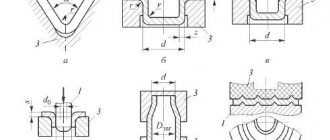
Basic forming operations: bending, drawing, flanging, crimping, spreading, relief molding. Schemes of forming operations are presented in Fig. 16.1.
Rice. 16.1. Form-forming operations of sheet stamping
Bending
– forming an angle between parts of the workpiece or giving the workpiece a curved shape.
When bending, only the section of the workpiece in the area of contact with the punch is plastically deformed. 1
(Fig. 16.1.a): the outer layers of the workpiece are stretched, and the inner layers are compressed. The tensile strain of the outer layers and the compression of the inner layers increases with a decrease in the radius of rounding of the working end of the punch, and the probability of crack formation increases. Therefore, the minimum radius of the punch is limited to a value within 0.1...2.0 of the workpiece thickness, depending on the mechanical properties of the material.
When the load is removed, the stretched layers of the workpiece are elastically compressed, and the compressed layers are stretched, which leads to a change in the bending angle, i.e. to the springing of the part. This should be taken into account either by reducing the angle of the tool by the amount of springing, or by applying additional force at the end of the working stroke.
Bending is carried out in dies, as well as with rotating shaped rollers, which act as a matrix, on profile bending mills.
Hood
– formation of a hollow product from a flat or hollow workpiece (Fig. 16.1.b).
The cut blank with diameter and thickness is laid on the plane of the matrix 3.
Punch
1
presses on the workpiece and it, moving into the hole of the matrix, forms the walls of an elongated part with a diameter of .
Shape change during drawing is assessed by drawing coefficient, which, depending on the mechanical characteristics of the metal and drawing conditions, should not exceed 2.1.
At , loss of stability of the flange and formation of folds during drawing are possible. They are prevented by pressing 2
workpiece flange to the matrix with a certain force.
Tall parts of small diameter are obtained through several drawing operations with a gradual decrease in the diameter D of the semi-finished product and an increase in its height (Fig. 16.1.c). During subsequent transitions, to prevent metal destruction, take
Intermediate annealing to eliminate work hardening allows you to increase it to 1.4...1.6.
The danger of workpiece destruction is eliminated by the use of lubricants to reduce the friction forces between the surfaces of the workpiece and the tool.
When drawing, the gap between the matrix and the punch is .
Beading
– obtaining a bead with a diameter by pressing the central part of the workpiece with a pre-punched hole into the matrix (Fig. 16.1.d).
The change in shape is assessed by the flanging coefficient
,
which depends on the mechanical characteristics of the metal of the workpiece and its relative thickness. A greater increase in diameter can be obtained if the workpiece is annealed before flanging or the hole is made by cutting, which creates less hardening at the edge of the hole.
Flanging is used for the manufacture of ring parts with flanges and for the formation of ledges in parts for threading, welding, as well as to increase structural rigidity with low weight.
The flanging of the outer contour stands out - the formation of low sides along the outer curved edge of the workpiece.
Crimping
– reduction of the cross-sectional perimeter of the end part of the hollow workpiece.
It is performed by pushing the workpiece into the tapering cavity of the matrix (Fig. 16.1.e). In one transition you can get . For greater shaping, several successive crimping operations are performed.
Giveaway
– increasing the perimeter of the cross section of the end part of the hollow workpiece with a conical punch; This is the opposite operation to crimping.
Relief molding
– local deformation of the workpiece in order to form a relief as a result of reducing the thickness of the workpiece (Fig. 16.1.e).
Molding produces structural projections and depressions, stiffeners, and labyrinth seals.
Dies for sheet stamping are divided according to technological criteria depending on the operation performed: cutting, bending, drawing, etc. Depending on the number of operations performed, single- and multi-operational stamps are distinguished. Multi-operational dies can be of sequential action, in which operations are performed sequentially when moving the workpiece across several working positions of the die, and combined action, in which operations are performed at one position, for example, simultaneously cutting and punching, cutting and drawing, etc.
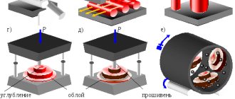
Currently, special die designs are used in which there are no metal punches or dies, and pressure on the material is carried out using rubber, liquid or compressed air (Fig. 16.2). In this case, rubber or liquid is easily removed from the stamped part, and the matrix must be detachable.
When making products of small depth, the punch is replaced by a rubber cushion (Fig. 16.2.a). With the help of rubber you can carry out all operations: cutting, bending, drawing, molding. Matrix 3
is attached to the table, and a rubber cushion placed in a steel clip
1
is attached to the running gear of the press (workpiece thickness
2
is up to 1.5 mm).
Rice. 16.2. Sheet stamping schemes using an elastic medium and liquid
Cylindrical rubber punches are used when drawing products of complex shapes, when it is necessary to increase the diametrical dimensions of the middle part of cylindrical semi-finished products (Fig. 16.2.b).
With hydraulic drawing (Fig. 16.2.c), hollow parts of cylindrical, conical, spherical or other shapes are obtained by pressing a liquid or a liquid enclosed in an elastic shell onto the workpiece.
High speed stamping methods
A feature of such methods is the high rate of deformation in accordance with high rates of energy conversion. A short-term application of high forces accelerates the workpiece to speeds of 150 m/s. Its subsequent deformation occurs due to the kinetic energy accumulated during the acceleration period. The main types of high-speed sheet stamping are: explosion stamping, electro-hydraulic and electromagnetic stamping (Fig. 16.3).
Rice. 16.3. a - electrohydraulic, b - electromagnetic stamping
Explosion stamping
carried out in pools filled with water (Fig. 16.3.a).
The workpiece 3
, sandwiched between the matrix
5
and the clamp
4,
is lowered into a pool of water
2
.
The matrix cavity under the workpiece is evacuated using vacuum line 6
.
The charge with detonator 1
is suspended in water above the workpiece. The explosion creates a high-pressure wave, which, upon reaching the workpiece, causes it to accelerate. The stamping process lasts thousandths of a second, and the speed of movement of the workpiece is comparable to the speed of propagation of plastic deformations in the metal. Explosion stamping does not require expensive pressing equipment; the design of the stamp is extremely simple.
Electrohydraulic stamping
also carried out in a pool of water. The shock wave that accelerates the workpiece occurs during a short-term electrical discharge in the liquid. A powerful spark discharge is like an explosion. As a result of the discharge, a shock wave appears in the liquid, which, upon reaching the workpiece, has a strong impact on it and deforms it along the matrix.
During electromagnetic stamping
(Fig. 16.3. b) electrical energy is converted into mechanical energy due to the pulsed discharge of a battery of capacitors through a solenoid
7
, around which an instantaneous high-power magnetic field appears, inducing eddy currents in a tubular conductive workpiece
3
. The interaction of the magnetic fields of eddy currents with the magnetic field of the inductor creates mechanical forces that deform the workpiece. For electromagnetic stamping of tubular and flat workpieces, installations have been created on which it is possible to carry out crimping, distribution, molding and operations for obtaining permanent connections of parts.
Formation of blanks from powder materials
Blanks from powder materials are produced by pressing (cold, hot), isostatic molding, rolling and other methods.
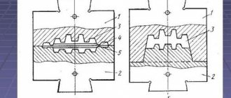
Cold pressed
3
is poured into the mold (Fig. 16.4.a) and pressed with a punch
1
.
During the pressing process, contact between particles increases, porosity decreases, and individual particles are deformed or destroyed. The strength of the resulting workpiece is achieved due to the forces of mechanical adhesion of powder particles by electrostatic forces of attraction and friction. With increasing pressing pressure, the strength of the workpiece increases. The pressure is distributed unevenly over the height of the pressed workpiece due to the influence of the friction forces of the powder on the walls of the mold, as a result of which the workpieces are obtained with different strength and porosity in height. Depending on the size and complexity of the pressed blanks, single- and double-sided pressing is used.
Fig. 16.4. Cold pressing scheme: a – one-sided; b – double-sided
Single-sided pressing produces blanks of simple shape with a height to diameter ratio of less than one, and blanks of bushings with a ratio of outer diameter to wall thickness of less than three.
Double-sided pressing (Fig. 16.4.b) is used to form workpieces of complex shapes. After filling the mold with powder, pressure is applied to the upper punch using a hydraulic press for pre-compression. Then the hydraulic drive is turned off and the lining is removed 4
. Subsequently, both punches participate in the pressing process. In this case, the required pressure to obtain uniform density is reduced by 30...40%. The use of vibration pressing makes it possible to reduce the required pressure tenfold.
During the pressing process, powder particles undergo elastic and plastic deformation. After removing the workpiece from the mold, its dimensions increase as a result of the elastic aftereffect.
With hot pressing
pressing and sintering of the workpiece are technologically combined. The hot pressing temperature is usually 0.6...0.8 of the melting point of the powder. Thanks to heating, compaction proceeds much more intensively than with cold pressing. This allows you to significantly reduce the required pressure. Hot pressing produces materials characterized by high strength and uniform structure. This method is used for poorly compressible compositions such as refractory metal-like compounds (carbides, borides, silicides).
Isostatic (all-round) molding
used to produce large-sized workpieces weighing up to 500 kg or more. The absence of losses due to external friction and uniform pressure on all sides make it possible to obtain the required density of workpieces at pressures significantly lower than when pressing in closed molds.
During hydrostatic molding (Fig. 16.5) into powder 3
, enclosed in an elastic shell
2
, pressure is transmitted using a liquid located in a high-pressure vessel
1
. Oil, glycerin, water, etc. are used as the working fluid.
Fig. 16.5. Hydrostatic molding scheme
Rolling
– the most productive and promising method of processing powder materials. A characteristic feature is a high degree of automation and continuous rolling. The rolling diagram is shown in Fig. 16.6.
Fig. 16.6. Powder rolling scheme
Powder is continuously supplied from the hopper 1
into the gap between the rolls.
When the rollers 3
2
is compressed and drawn into a tape or strip
4
of a certain thickness. Rolling can be combined with sintering and final processing of the resulting workpieces. In this case, the strip is passed through a sintering oven and then rolled again to produce sheets of specified dimensions. Using bins with a partition (Fig. 16.6.b), belts are made from different materials (two-layer). The use of rolls of a certain shape makes it possible to obtain rolls of various profiles, including wire.
Separation operations
are intended either for obtaining a workpiece from a sheet or tape, or for separating one part of the workpiece from another. Operations can be performed along a closed or open loop.
The separation of one part of the workpiece from another is carried out by a relative displacement of these parts in a direction perpendicular to the plane of the workpiece. This displacement is initially characterized by plastic deformation and ends with destruction.
Segment
– separation of part of the workpiece along an open contour using special machines – scissors or stamps.
It is usually used as a procurement operation for dividing sheets into strips and blanks of the required size.
The main types of scissors are shown in Fig. 15.5.
Rice. 15.5. Schemes of operation of scissors: a – guillotine; b – disk
Scissors with translational movement of the cutting edges of the knife can be with parallel knives, for cutting narrow strips, with one inclined knife - guillotine (Fig. 15.5.a). The cutting edges in guillotine shears are inclined to each other at an angle of 1...50 to reduce the cutting force. The sheet is fed until it stops, which determines the width of the cut strip B
. The length of the cut strip L should not exceed the length of the knives.
Scissors with rotational movement of the cutting edges are disk scissors (Fig. 15.5.b). The length of the cut piece is not limited by the tool. The rotation of the disc knives not only ensures separation, but also feeds the workpiece under the influence of friction forces. The cutting edges of the knives overlap one another, this ensures the straightness of the cutting line. To ensure gripping and feeding of the workpiece, the diameter of the knives must be 30...70 times greater than the thickness of the workpiece, increasing as the friction coefficient decreases.
Felling
and
punching
- separation of metal along a closed contour in a die.
When cutting and punching, the nature of the workpiece deformation is the same. These operations differ only in purpose. The outer contour of the part is formed by cutting, and the inner contour is formed by punching (making holes).
Cutting and punching are carried out with a metal punch and matrix. The punch presses part of the workpiece into the die hole. A diagram of the cutting and punching processes is shown in Fig. 15.6.
The main technological parameter of the operations is the radial gap between the punch and the matrix. The gap is assigned depending on the thickness and mechanical properties of the workpiece; it is approximately . When punching, the dimensions of the die hole are equal to the dimensions of the product, and the dimensions of the punch are smaller than them. When punching, the size of the punch is equal to the dimensions of the hole, and the dimensions of the matrix are larger than them.
Rice. 15.6. Scheme of the cutting (a) and punching (b) processes
1 – punch, 2 – matrix, 3 – product, 4 – waste
Reducing the cutting force is achieved by making a bevel on the matrix when cutting, and on the punch when punching.
When stamping small and medium-sized parts, several flat blanks are cut out from one sheet blank for stamping. Between the adjacent contours of the cut-out workpieces, jumpers are left with a width approximately equal to the thickness of the workpiece. In some cases, adjacent workpieces are cut out without jumpers (saving metal while deteriorating the quality of the cut and reducing tool life).
The arrangement of the contours of adjacent cut-out blanks on sheet material is called cutting. The part of the workpiece remaining after cutting is die-cutting.
Die cutting constitutes the main waste in sheet metal stamping. The type of cutting should be selected based on the condition of reducing metal waste in the die cutting (Fig. 15.7).
Fig. 15.7. Examples of cutting material with jumpers (a) and without jumpers (b)
Metal savings can be achieved by: reducing metal consumption for jumpers, using waste-free and low-waste cutting, increasing the accuracy of calculating the dimensions of the workpiece and reducing allowances for cutting.
LECTURE 16
Cold stamping (continued)
Formation of blanks from powder materials
Sheet stamping
Form-forming operations of sheet stamping
During forming operations, one strives to obtain a given amount of deformation so that the workpiece acquires the required shape.
Basic forming operations: bending, drawing, flanging, crimping, spreading, relief molding. Schemes of forming operations are presented in Fig. 16.1.
Rice. 16.1. Form-forming operations of sheet stamping
Bending
– forming an angle between parts of the workpiece or giving the workpiece a curved shape.
When bending, only the section of the workpiece in the area of contact with the punch is plastically deformed. 1
(Fig. 16.1.a): the outer layers of the workpiece are stretched, and the inner layers are compressed. The tensile strain of the outer layers and the compression of the inner layers increases with a decrease in the radius of rounding of the working end of the punch, and the probability of crack formation increases. Therefore, the minimum radius of the punch is limited to a value within 0.1...2.0 of the workpiece thickness, depending on the mechanical properties of the material.
When the load is removed, the stretched layers of the workpiece are elastically compressed, and the compressed layers are stretched, which leads to a change in the bending angle, i.e. to the springing of the part. This should be taken into account either by reducing the angle of the tool by the amount of springing, or by applying additional force at the end of the working stroke.
Bending is carried out in dies, as well as with rotating shaped rollers, which act as a matrix, on profile bending mills.
Hood
– formation of a hollow product from a flat or hollow workpiece (Fig. 16.1.b).
The cut blank with diameter and thickness is laid on the plane of the matrix 3.
Punch
1
presses on the workpiece and it, moving into the hole of the matrix, forms the walls of an elongated part with a diameter of .
Shape change during drawing is assessed by drawing coefficient, which, depending on the mechanical characteristics of the metal and drawing conditions, should not exceed 2.1.
At , loss of stability of the flange and formation of folds during drawing are possible. They are prevented by pressing 2
workpiece flange to the matrix with a certain force.
Tall parts of small diameter are obtained through several drawing operations with a gradual decrease in the diameter D of the semi-finished product and an increase in its height (Fig. 16.1.c). During subsequent transitions, to prevent metal destruction, take
Intermediate annealing to eliminate work hardening allows you to increase it to 1.4...1.6.
The danger of workpiece destruction is eliminated by the use of lubricants to reduce the friction forces between the surfaces of the workpiece and the tool.
When drawing, the gap between the matrix and the punch is .
Beading
– obtaining a bead with a diameter by pressing the central part of the workpiece with a pre-punched hole into the matrix (Fig. 16.1.d).
The change in shape is assessed by the flanging coefficient
,
which depends on the mechanical characteristics of the metal of the workpiece and its relative thickness. A greater increase in diameter can be obtained if the workpiece is annealed before flanging or the hole is made by cutting, which creates less hardening at the edge of the hole.
Flanging is used for the manufacture of ring parts with flanges and for the formation of ledges in parts for threading, welding, as well as to increase structural rigidity with low weight.
The flanging of the outer contour stands out - the formation of low sides along the outer curved edge of the workpiece.
Crimping
– reduction of the cross-sectional perimeter of the end part of the hollow workpiece.
It is performed by pushing the workpiece into the tapering cavity of the matrix (Fig. 16.1.e). In one transition you can get . For greater shaping, several successive crimping operations are performed.
Giveaway
– increasing the perimeter of the cross section of the end part of the hollow workpiece with a conical punch; This is the opposite operation to crimping.
Relief molding
– local deformation of the workpiece in order to form a relief as a result of reducing the thickness of the workpiece (Fig. 16.1.e).
Molding produces structural projections and depressions, stiffeners, and labyrinth seals.
Dies for sheet stamping are divided according to technological criteria depending on the operation performed: cutting, bending, drawing, etc. Depending on the number of operations performed, single- and multi-operational stamps are distinguished. Multi-operational dies can be of sequential action, in which operations are performed sequentially when moving the workpiece across several working positions of the die, and combined action, in which operations are performed at one position, for example, simultaneously cutting and punching, cutting and drawing, etc.
Currently, special die designs are used in which there are no metal punches or dies, and pressure on the material is carried out using rubber, liquid or compressed air (Fig. 16.2). In this case, rubber or liquid is easily removed from the stamped part, and the matrix must be detachable.
When making products of small depth, the punch is replaced by a rubber cushion (Fig. 16.2.a). With the help of rubber you can carry out all operations: cutting, bending, drawing, molding. Matrix 3
is attached to the table, and a rubber cushion placed in a steel clip
1
is attached to the running gear of the press (workpiece thickness
2
is up to 1.5 mm).
Rice. 16.2. Sheet stamping schemes using an elastic medium and liquid
Cylindrical rubber punches are used when drawing products of complex shapes, when it is necessary to increase the diametrical dimensions of the middle part of cylindrical semi-finished products (Fig. 16.2.b).
With hydraulic drawing (Fig. 16.2.c), hollow parts of cylindrical, conical, spherical or other shapes are obtained by pressing a liquid or a liquid enclosed in an elastic shell onto the workpiece.
High speed stamping methods
A feature of such methods is the high rate of deformation in accordance with high rates of energy conversion. A short-term application of high forces accelerates the workpiece to speeds of 150 m/s. Its subsequent deformation occurs due to the kinetic energy accumulated during the acceleration period. The main types of high-speed sheet stamping are: explosion stamping, electro-hydraulic and electromagnetic stamping (Fig. 16.3).
Rice. 16.3. a - electrohydraulic, b - electromagnetic stamping
Explosion stamping
carried out in pools filled with water (Fig. 16.3.a).
The workpiece 3
, sandwiched between the matrix
5
and the clamp
4,
is lowered into a pool of water
2
.
The matrix cavity under the workpiece is evacuated using vacuum line 6
.
The charge with detonator 1
is suspended in water above the workpiece. The explosion creates a high-pressure wave, which, upon reaching the workpiece, causes it to accelerate. The stamping process lasts thousandths of a second, and the speed of movement of the workpiece is comparable to the speed of propagation of plastic deformations in the metal. Explosion stamping does not require expensive pressing equipment; the design of the stamp is extremely simple.
Electrohydraulic stamping
also carried out in a pool of water. The shock wave that accelerates the workpiece occurs during a short-term electrical discharge in the liquid. A powerful spark discharge is like an explosion. As a result of the discharge, a shock wave appears in the liquid, which, upon reaching the workpiece, has a strong impact on it and deforms it along the matrix.
During electromagnetic stamping
(Fig. 16.3. b) electrical energy is converted into mechanical energy due to the pulsed discharge of a battery of capacitors through a solenoid
7
, around which an instantaneous high-power magnetic field appears, inducing eddy currents in a tubular conductive workpiece
3
. The interaction of the magnetic fields of eddy currents with the magnetic field of the inductor creates mechanical forces that deform the workpiece. For electromagnetic stamping of tubular and flat workpieces, installations have been created on which it is possible to carry out crimping, distribution, molding and operations for obtaining permanent connections of parts.
Formation of blanks from powder materials
Blanks from powder materials are produced by pressing (cold, hot), isostatic molding, rolling and other methods.
Cold pressed
3
is poured into the mold (Fig. 16.4.a) and pressed with a punch
1
.
During the pressing process, contact between particles increases, porosity decreases, and individual particles are deformed or destroyed. The strength of the resulting workpiece is achieved due to the forces of mechanical adhesion of powder particles by electrostatic forces of attraction and friction. With increasing pressing pressure, the strength of the workpiece increases. The pressure is distributed unevenly over the height of the pressed workpiece due to the influence of the friction forces of the powder on the walls of the mold, as a result of which the workpieces are obtained with different strength and porosity in height. Depending on the size and complexity of the pressed blanks, single- and double-sided pressing is used.
Fig. 16.4. Cold pressing scheme: a – one-sided; b – double-sided
Single-sided pressing produces blanks of simple shape with a height to diameter ratio of less than one, and blanks of bushings with a ratio of outer diameter to wall thickness of less than three.
Double-sided pressing (Fig. 16.4.b) is used to form workpieces of complex shapes. After filling the mold with powder, pressure is applied to the upper punch using a hydraulic press for pre-compression. Then the hydraulic drive is turned off and the lining is removed 4
. Subsequently, both punches participate in the pressing process. In this case, the required pressure to obtain uniform density is reduced by 30...40%. The use of vibration pressing makes it possible to reduce the required pressure tenfold.
During the pressing process, powder particles undergo elastic and plastic deformation. After removing the workpiece from the mold, its dimensions increase as a result of the elastic aftereffect.
With hot pressing
pressing and sintering of the workpiece are technologically combined. The hot pressing temperature is usually 0.6...0.8 of the melting point of the powder. Thanks to heating, compaction proceeds much more intensively than with cold pressing. This allows you to significantly reduce the required pressure. Hot pressing produces materials characterized by high strength and uniform structure. This method is used for poorly compressible compositions such as refractory metal-like compounds (carbides, borides, silicides).
Isostatic (all-round) molding
used to produce large-sized workpieces weighing up to 500 kg or more. The absence of losses due to external friction and uniform pressure on all sides make it possible to obtain the required density of workpieces at pressures significantly lower than when pressing in closed molds.
During hydrostatic molding (Fig. 16.5) into powder 3
, enclosed in an elastic shell
2
, pressure is transmitted using a liquid located in a high-pressure vessel
1
. Oil, glycerin, water, etc. are used as the working fluid.
Fig. 16.5. Hydrostatic molding scheme
Rolling
– the most productive and promising method of processing powder materials. A characteristic feature is a high degree of automation and continuous rolling. The rolling diagram is shown in Fig. 16.6.
Fig. 16.6. Powder rolling scheme
Powder is continuously supplied from the hopper 1
into the gap between the rolls.
When the rollers 3
2
is compressed and drawn into a tape or strip
4
of a certain thickness. Rolling can be combined with sintering and final processing of the resulting workpieces. In this case, the strip is passed through a sintering oven and then rolled again to produce sheets of specified dimensions. Using bins with a partition (Fig. 16.6.b), belts are made from different materials (two-layer). The use of rolls of a certain shape makes it possible to obtain rolls of various profiles, including wire.
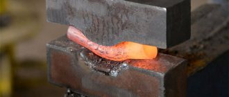
Flanging process - main stages
The technology provides for the execution of an operation in several transitions. For example, to obtain an edge of 40 mm, it is necessary to extend the edge of the pipe to the sides by 10-15 mm more than the height of the pipe. It will be 50-55 mm, and the diameter of the pipe should be observed during further operation (Fig. b).
When making a bend at a height of 40 mm from the edge of the pipe, without a preliminary breakdown, a narrowing of the diameter will be observed (Fig. c).
After the end of the pipe has been split, the flanging operation begins. To do this, the part is installed on an anvil (Fig. d) and blows are applied obliquely with a hammer, preventing the appearance of cracks on the edge. To avoid defects, processing should not be carried out by weight. The bending of the edges is carried out sequentially, in two or three steps, until 90° is reached.
The hammer blows should be evenly distributed along the entire edge, without making excessive blows at one point. When beading and after receiving the edge, you should straighten the bend on the tip using an ironing hammer.
Carrying out flanging manually is a labor-intensive operation, takes a lot of working time, and requires the consumption of larger quantities of material. During this operation, it is recommended to use devices and auxiliary tools, mandrels and machine tools that significantly increase productivity and quality work characteristics.