A plane is a traditional carpenter's tool, a kind of symbol of this profession. The shape of the instrument and the methods of working with it, despite its technical improvement over many years, have not essentially changed.
In order for the process of planing a wooden workpiece to proceed “without a hitch” (as evidenced by the twisted shavings freely coming out of the slot in the plane block), it is necessary to accurately adjust the plane knife and correctly move the plane along the surface being planed.
Planing is a real pleasure when thin and long twisted shavings fly out of the plane.
Having fixed the plane knife with the chipbreaker exposed in the vice of the workbench, lightly tighten the screw. After wedging, the chipbreaker fixes itself due to its springiness.
Insert the knife into the tap hole of the plane and first secure the wedge in its guides by hand.
To determine whether the knife is positioned correctly (its blade should be parallel to the plane of the sole of the plane and slightly protruding above it), you simply need to turn the plane over and evaluate the mutual parallelism of the knife blade and the sole by eye. To adjust (if necessary) the position of the knife, release the wedge, align the knife correctly and fix it again with the wedge.
When planing the faces of workpieces, the knife should remove chips of uniform thickness. To do this, you need to adjust the chipbreaker of a jointer, a double plane (with a double blade) or a sander. The chipbreaker performs the function corresponding to its name and should be installed slightly above (about 1 mm) the knife blade and fit snugly against it.
First, the knife with the chipbreaker fixed on it is inserted into the slot (tap) of the block (body) and slightly wedged. Then set the knife with light blows of the hammer so that its blade is parallel to the sole of the plane and protrudes slightly above it. After this, the knife is finally fixed in the block with a wedge, screw or cam clamp (depending on the design of the plane).
Since during planing the upper part of the worker’s body moves together with the plane, the carpenter must stand on the side parallel to the workpiece being processed, with one leg placed forward. To prevent the plane from tipping over at the beginning and end of the workpiece (then the surface being processed in these areas will be uneven), you should lean harder first on its front handle, and then on the back handle at the exit.
PRECISION PLANE
In modern planes with a metal block, the blade is usually secured with a screw. With another screw (set screw), you can adjust the plane to the required thickness of the chips being removed with an accuracy of hundredths of a millimeter. In addition, such planes are equipped with a so-called knife tilt regulator, which allows you to quickly, just by pressing the thumb on the corresponding lever, correctly position the knife blade relative to the sole of the plane.
EDGE PLANING
When planing the edges of flat workpieces, you should move the plane along an even path along the entire length of the workpiece, leaning evenly on it. In this case, the knife must be secured securely so that it does not vibrate in the block. In addition, you should avoid tearing the chips by cutting in the direction of the wood grain. When processing wood pieces with thin and irregular texture (for example, root), the knife must be sharpened very well. When planing, such a workpiece should be constantly rotated.
It is more convenient to plan a narrow edge using, for example, a piece of board pressed against the workpiece, or plan simultaneously the edges of several thin boards collected in a package. In this case, the supporting surface for the sole of the plane increases.
To prevent the edge from becoming rounded, the plane must be held level, without tilting in any direction.
With Sherhebel you can remove a thicker layer of material in one pass.
Planing the end of the workpiece will be much easier if you hold the plane at an angle to the faces of the workpiece.
Wide wooden overlays, attached with a clamp to both edges of the workpiece, will prevent chipping when processing the end.
The surfaces of short-length workpieces are very smooth with a silky shine after processing with just a sander.
When planing layers, it is necessary to constantly check their processed surface with a steel square.
When processing long workpieces, a jointer has proven itself best, as it can be used to plane even against the grain.
PLANING PLATES
To make a rough but even surface smooth, it is enough to treat it with a sander (a tool with a knife angle increased to 60° for fine planing of hard-to-cut wood) and a jointer. To eliminate unevenness or remove a thicker layer, treatment with Sherhebel will be required. The latter is equipped with a narrow (33 mm wide) convex knife with an oval blade, capable of removing chips up to 3 mm thick in one pass. After this, the surface must be leveled with a sander and “smoothed” with a jointer.
CLEANING THE ENDS
When cleaning the ends of the workpieces, the plane is driven in the direction “away from you”, making short pushes with it. In this case, the wood fibers are cut crosswise, which requires somewhat greater effort and the use of a very sharp knife. To avoid chipping at the edge in the direction in which the end of the workpiece is being machined, you can first chamfer this edge. It’s better to first process one half of the end to the middle, and then, turning the workpiece 180°, the second half.
More than during operation, the blades deteriorate from contact with foreign objects when the plane is not used. During breaks in work, the plane should be placed on its side or with the front of the sole on a wooden stand. During long-term storage or when transporting the plane in a tool box, the knife should be placed inside the block.
Source: niola-td.ru
How to choose and use an electric planer correctly
An electric plane is an essential tool for anyone who deals with wood processing, and during construction or renovation it can become an indispensable assistant. In everyday life, a traditional hand plane is usually enough for a home craftsman, but in a private farmstead or summer cottage there is plenty of woodworking. Baths, outbuildings, fences, benches and other furniture - the list goes on and on.
An electric planer will save the craftsman a lot of time and effort and allow him to achieve good results. Using an electric planer, workpieces are brought to the required dimensions, surfaces are leveled, nicks, burrs and knots are removed, edges are cut, and grooves are selected. A plane, of course, is not capable of “fine” processing of surfaces to perfect smoothness; this will require additional tools. But with its main task - rough processing of wood in large volumes - the electric planer, if the operating rules are followed, copes “excellently”.
As when choosing any power tool, when choosing an electric planer, a master should start from the main tasks in which the tool will be most often involved. An important role is played by the power of the tool, which is directly related to its performance. A plane of greater power plans “deeper”, that is, it can remove a thicker layer of wood in one pass. Manual electric planers are produced with a power ranging from 0.5 to 2.2 kW. Above one and a half kilowatts is, in fact, a professional tool for large-scale work. If you plan to use the plane frequently and in large volumes, it makes sense to take a closer look at more powerful models. But, as always, the rule applies: the more powerful the tool, the more it weighs and the higher its price. It will be convenient to work with a low-power plane while suspended. Medium power models weigh between 2.5-4 kg.
Another indicator is the rotation frequency of the drum, that is, the number of revolutions it makes per unit of time. This value is very important to consider when choosing a plane, says FORUMHOUSE wind1wind: the higher the number of revolutions, the better the quality of the cut. The optimal option that you should focus on when choosing is 15000-16000 rpm.
wind1wind:
– The plane does not create a completely flat surface, but a “wave” with very fine steps. To make this waviness invisible, the number of shaft revolutions and the number of knives on the shaft are increased. These two parameters are very important when choosing.
Working with carpentry planes and caring for them
The modern carpenter's plane is a very carefully crafted tool, but as with all mass-produced products, a little adjustment can make a big difference in its performance. In any case, all planes require maintenance and are adjusted from time to time to keep them operating at peak efficiency.
Disassembling a metal plane
To remove the knife, first lift the lever on the clamp and remove it from under its locking screw. Remove the knife with chipbreaker from the housing. Use a large screwdriver to loosen the chipbreaker locking screw and slide it toward the cutting edge until the head of the screw fits through the hole in the blade, releasing both parts.
Adjusting the frog
After removing the knife with the chipbreaker, access to the “frog” opens. This wedge-shaped cast part combines the blade's reach and windage adjustment. The frog can move itself up and down, thereby adjusting the size of the slot in the body of the plane through which the knife passes.
For rough planing, the slot is open for thick chips. If the knife is installed for fine (finish) planing, the slot is narrowed, which promotes breaking off and twisting of thin chips around the chipbreaker. To adjust the frog, loosen its two locking screws and turn the adjustment screw with a screwdriver. Tighten the locking screws.
How to work with an electric planer correctly?
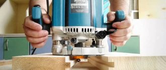
Many beginners are interested in the question of how to work with an electric planer. At first glance, there is nothing complicated: plug it into a power outlet, press a button, move it back and forth across the surface, removing chips. However, during the first attempts, the result is not always impressive.
When purchasing a tool, you need to check its functionality, completeness and appearance. It is worth paying attention to the sharpening quality of the installed knives. If the kit contains spare knives, you need to check them too. The cutting edge should be smooth, sharp, without gouges or bends. All other settings should be checked at home in accordance with the manufacturer's instructions.
Defects of a carpenter's plane
There is virtually no doubt that your plane will perform its functions perfectly immediately after purchasing it. However, if you still have problems getting the desired result, check if the tool has a problem. the most obvious defects.
Set the desired slot width using the screw located behind the horn. Sole deformation If you cannot get a straight planer, use a straight edge to make sure there is no deformation of the sole. The metal sole can be straightened using an emery cloth glued with double-sided tape to a sheet of glass.
Of course, this is a slow and labor-intensive process, and you can take the plane to a specialist to correct the defect (or return it to the seller). Leveling a wooden plane on sandpaper is easier.
Remove the knife, grab the plane by the middle of the body and move it along the sandpaper. Check the result with a straight edge. Knife vibration A poorly secured knife will vibrate and slip on the workpiece.
Tighten the chip breaker lock screw or tension screw nut. If the defect has not disappeared, check whether a foreign object has entered the space behind the knife, or, in the case of a metal plane, under the “frog”.
Chips get stuck under the chipbreaker
If the chipbreaker is not securely attached to the knife, chips will get stuck under the leading edge of the chipbreaker. If the knife is bent, place it on a flat, level board and hit it with a hammer. Sand the end of the chipbreaker until it is flat. General recommendations Wooden soles become smooth and slippery when used and should not be treated in any way. To ease the movement of a “sticking” plane, rub its sole with a candle.
Checking and adjusting the position of the front plate
All adjustments to the tool must be made in the off state. The plug must be unplugged from the socket, otherwise you can not only damage the electric planer, but also cause serious injury.
Table of main parameters of electric planers.
When checking the position of the knives, the front plate must be set to the minimum planing depth position using the standard adjustment knob. Place the electric planer on a flat, hard surface with the drum facing up.
To check, you can use a metal ruler or a piece of window glass of suitable dimensions. The drum with knives should be rotated until one of the knives is in the upper position, above the drum axis. The ruler or glass must be laid on the slabs along the plane. The surfaces must be in the same plane.
If the control device on any of the plates is tilted, you need to check the position of the front plate and adjust it. Such a defect occurs during long-term operation of the tool without maintenance. The internal cavities can become clogged with wood dust and small shavings. Excessive force on the depth adjustment handle displaces it from its original position.
To eliminate the defect, you need to remove the handle, the front plate, clean the cavities from dust and chips, and lubricate them. Place the plate in place, check the installation using a ruler, secure the handle, checking that the dial matches the index mark.
Step-by-step instructions for getting maximum performance from any plane.
There's a closely guarded secret in carpentry: Most new planes should be thought of as a collection of parts, not as a ready-to-go tool...
Recently, while preparing a review of a new plane, I set it to 0.02 or 0.05 mm chip thickness; This is a reasonable setting for hardwoods with a figured grain pattern, but achieving a straight edge proved impossible.
I discovered that the source of the problem was the plane sole, which was 0.08mm concave along its length. Unaware of such defects, many amateur carpenters remain dissatisfied with their new planes; This also annoyed me in the beginning, and my new students are facing the same problem.
In the heyday of plane making in England, a Norris or Spiers plane cost a carpenter 2-3 weeks' wages, and we shouldn't expect too much from a new Stanley or Anant plane that costs us a few hours' wages. On the other hand, the same few hours spent on tuning will lead to a very noticeable improvement in their performance.
The methods I describe in this article apply to all metal-bodied Bailey planes, both vintage and new.
Planer parts
In order for a plane to plan cleanly and without vibration, its parts must be processed with high precision and fit perfectly together. It is unlikely that you will find such quality in a mass-produced plane. However, after adjusting the parts yourself and replacing the blade with a new one, your $80 plane will plane as well as a $300 model.
Lever-clamping mechanism (Clamp. Cover). Grinding the bottom surface allows for easier depth adjustment.
Chipbreaker (Gorbatik). Slight modification of the shape of the top and bottom surfaces will allow the chips to slide off without getting stuck.
Blade (Iron). The new A2 cryogenic steel blade holds an edge longer than the original.
Frog (Wedge). The frog connects the blade to the body. Poor contact with one or the other leads to vibration and “battering”.
Planer body (block). Only a perfectly flat sole will allow you to remove shavings through which you can read newspaper font. The area where the frog is attached must be flat.
A new blade is a worthwhile investment
The easiest way to improve your plane is to purchase a higher quality piece of cryogenically treated A2 steel. They are made by Ron Hock (www.hocktools.com) and Tomas Lie-Nielsen (www.lie-nielsen.com), but if you buy from the latter, be sure to ask for a 2.4 mm (0.095 in) thick blade as the thicker A 3.3 mm (0.130 inch) blade may not fit your plane. Even a 2.4mm blade will be significantly thicker and stiffer than stock, and will greatly reduce vibration and chatter.
Adjusting the frog to avoid distortion
The frog connects the body and blade of the plane. It is important that it fits tightly to the body and has a flat surface in contact with the blade. A well-fitted frog significantly reduces “bounce” when planing.
The setup begins with disassembling the plane, removing the frog and checking its seat - the four points of contact between the body and the bottom surface of the frog. A poorly fitted frog, if screwed tightly, will warp the thin part of the sole just behind the mouth of the plane.
Scrape down any raised areas
Use a scraper to scrape off the metal from the high areas and increase the area of contact between the frog and the body.
To determine how well the surfaces fit, color in the corresponding areas of the casting with a black felt-tip pen. Remove the longitudinal adjustment bolt stop plate (some planes have it attached to the back wall of the frog, others may not have it), put the frog in place, and move it back and forth. The marker ink will scrape off where the surfaces are in good contact.
If the frog swings, then contact will only be at two diagonally opposite points. Approximately 60% contact should be achieved across all four sites. Although it is slower, I prefer to use a scraper rather than a file for this. It is very easy to remove too much metal with a file and ruin your plane. If you don't have a scraper, you can make one from a 15-centimeter flat file.
Grind the last 2-3 centimeters of the file length so that both flat sides are slightly concave and the end is convex. For final finishing, place a pinch of 180 or 220 grit silicon carbide on each scraped surface and add a drop of water. Rub the surfaces for a few minutes, moving the frog back and forth until the surfaces are a dull gray. Try to achieve 90% contact between both surfaces.
Creating the corner of the mouth. Refinement of the mouth will prevent chips from getting stuck
Start by notching the leading edge of the mouth. Degrease the sole of the plane and color the area in front of the leading edge of the mouth with a black marker. Scratch a shallow score across the sole as close to the current edge as possible. This is the marking for the next step, grooving.
Chips can be driven into the gap between the blade and the chipbreaker.
The narrow mouth prevents fibers from being pulled out, but on an unprepared plane it will become clogged with shavings. If you ground the leading edge at 15 degrees and finish it with a chipbreaker, it will be easier for the chips to escape from this bottleneck.
The bent end of the chipbreaker is turned and polished. The edge of the mouth, ground to 15 degrees, creates additional space for chips to escape. The underside of the chipbreaker is chamfered to ensure tight contact with the blade.
Clamp the plane in a vice at an angle of 15° to the vertical. It is very important that the jaws of the vice apply pressure where the side walls of the casting are supported by the transverse rib. Clamping anywhere else can break the plane's fragile sides.
Hold the file horizontally, using the top edge of the vise jaws as a guide. As processing progresses, a light stripe will show where metal is being removed. Gradually, a burr edge will form on the sole. Watch the scratched line so that the mouth remains narrow and even. Be especially careful not to grind off the metal from the sides of the mouth. A fine file produces a smooth surface and crisp, right angles. Then buff with 600 grit waterproof sanding paper followed by metal polishing paste. and steel wool for excellent results.
To prepare the mouth for cutting, color the sole with a black marker, then draw a line as close to the mouth as possible (photo above). After this, clamp the plane in a vice at an angle of 15° to the vertical. Holding the file parallel to the vice, gradually grind the mouth to an angle of 15° until the cut edge reaches the drawn line.
Working with the top surface of the frog
Many new planes have a noticeable concave in an important section of the top surface of the frog, which supports the piece of iron just behind the cutting edge. This causes vibration when planing. A rough surface can also prevent smooth adjustment of the blade. The top surface of the frog does not need to be polished to a mirror finish; it is enough to obtain a general plane.
Apply 240 grit waterproof sanding paper to a flat surface. Draw stripes across the top surface of the frog with a felt-tip pen to show how sanding is progressing. Move the frog back and forth across the paper, maintaining full contact, without rocking.
The upper part will have to be sanded using a small block wrapped in sandpaper, due to the protruding skew adjustment lever. Remove the sharp and rough edges of the frog with a fine file.
In addition, I usually polish the areas of the slingshot arm that come into contact with the bronze adjustment wheel. The surface of the “slingshot” can be rough after casting, and gradually wears out the softer metal of the wheel, increasing the adjustment play over the years.
Sand with a chipbreaker
The edges of the chipbreaker are one of the most inconsistent quality areas on a plane. The lower edge of the chipbreaker should fit snugly, without gaps, against the blade so that chips do not get stuck between them. To do this, make a small chamfer on the bottom edge by sanding it with a diamond stone or waterproof sanding paper of 240 grit.
To ensure the correct angle, place a small piece of wood under the chipbreaker. To check the result, make sure that no light penetrates into the gap between the chipbreaker and the blade. The top surface of the chipbreaker also needs to be modified.
Clamp the chipbreaker into the sharpening mandrel at 45°, and grind off some metal on a diamond stone. Pull it out 2.5mm at a time to form a series of narrow chamfers, which you then smooth with 400 grit sandpaper.
Finally, polish the surface with metal sanding paste to ensure there is nothing obstructing the sliding of the chips.
Process the lever-pressure insert
The underside of the pressure insert often has a rough surface with sand mold marks. It can be smoothed using 240 grit waterproof sanding paper applied to a smooth surface. The smooth insert holds the blade better and adjusts more smoothly.
Assembling the plane and adjusting the position of the frog
Before assembling the plane, oil all unpainted surfaces to prevent rusting. The stop plate of the longitudinal adjustment screw sometimes needs to be tilted to the side so that the frog sits in the center of the body. Lightly tighten the frog clamping screws so that it can be moved back and forth with the adjustment screw. To determine the correct position of the frog, insert the blade and adjust it to obtain fine, even chips. Run a small piece of wood along the sole across the blade to determine where and how the blade planes.
Now look at the mouth from the side of the sole: the edge of the blade should be parallel to the front edge of the mouth. If it is not parallel, then move the frog without touching the blade skew lever and achieve parallelism.
For beginners, I recommend setting the gap to 0.4-0.5 mm. Experienced woodworkers can set the gap to 0.15 mm on their favorite finishing plane.
For minor adjustments, it is often easier to tighten one of the screws on the frog so that it rotates slightly as the head rotates. Be prepared to take a few tries until you get the frog just right.
When you achieve parallelism of the blade and the desired gap, carefully remove the blade without moving the frog, and finally tighten the clamping screws. Do not apply too much force, otherwise the thin part of the sole behind the mouth may burst. Tighten just enough so that the frog doesn't move.
Before sanding the sole, it is recommended to tighten all screws to working condition and retract the blade. This is necessary because the pressure of the lever-clamping insert can slightly deform the sole (this especially applies to chisels and end-mortise planes.)
The screw of the lever-clamping insert must be adjusted so that with the force of your thumb the lever is fixed clearly, but without tension. Often the pressure insert adjustment screw does not sit tightly in its threaded hole in the frog. When adjusting the blade extension, it swings and causes additional play.
In this case, unscrew the screw and note the number of turns, degrease it, drop a few drops of liquid Loctite into the threaded hole, and screw the screw in the same number of turns.
Ensuring the sole is flat
The most noticeable improvement in the performance of the plane comes from grinding the sole. For this I use a piece of polished glass 10-15 mm thick. The glass bends slightly and can take the bends of the surface on which it lies, so check its flatness with a ruler with a straight edge, and, if necessary, place sheets of newspaper in low places. It is better if the length of the glass is slightly concave than slightly convex, so that in the middle you can insert a piece of tissue paper under the edge of the ruler.
Glue sheets of waterproof paper onto the glass with spray adhesive, leaving centimeter gaps between them.
In most cases you can start with 100 grit, but for a #7 or #8, or even a #5 in poor condition, start with 60 grit.
Apply 150 and 180 grit sheets, finishing with 240 or 320 grit.
Sanding is done on the roughest paper; finer grits simply remove the scratches from the previous one. Rough numbers can be used dry and the sawdust can be removed with a vacuum cleaner, but to prevent 240 or 320 grit paper from clogging, you need to use kerosene.
To check the condition of the sole, draw stripes across it with a black marker. The most important areas are the toe, heel, and areas just in front and behind the mouth.
If these stripes disappear when sanding at the same speed, then the soleplate is smooth enough to work well.
Removing sharp edges and protecting metal from rust
Using sandpaper of the last grit on the side edges of the sole, I make a chamfer 0.4 mm wide. On the leading and trailing edges, I file a wider chamfer at an angle of 30°. The last narrow chamfer is removed from the rear edge of the mouth, which otherwise could scratch the wood being planed.
Vacuum up any metal filings and thoroughly wipe the soleplate with steel wool and metal polish.
To protect against rust, apply several coats of silicone-free finishing wax to the sides and sole of the plane.
After each use, before putting the plane back in place, I wipe down the unpainted sides and sole with camellia oil. Before work, remove the oil with a cloth.
Now you can test the plane on thin-grained wood, such as maple or cherry. With a well-sharpened piece of iron, you can easily achieve chips 0.025 mm thick, through which you can read newspaper font.
Adjusting the position of the cutting edge
Adjustment of the position of the knives is carried out according to two parameters:
- height of the cutting edge relative to the back plate;
- the size of the protruding part of the knife for planing quarters.
Layout of the drum with blades.
Having installed the ruler or glass, you need to rotate the drum, controlling the gap between the knife and the device at the edges of the slabs. The edge of the knife should lightly touch the tool without lifting it. If the knife clings to the device or does not reach it, the position must be adjusted.
Typically, knives are secured with a special wedge with expansion bolts. Using an 8 or 10 wrench, you need to screw the bolts into a wedge until the bolt moves freely. Then, using the installed eccentrics, align the height of the cutting edge with the device. Tighten (unscrew) the mounting bolts and check the position again. The desired result can be achieved after several repetitions of this operation.
At the same time as adjusting the height of the cutting edge, you need to control the protruding part of the quarter planing knife. The optimal size should be indicated in the manufacturer's instructions. On most models it is 1 mm. The size is set by moving the knife left or right along the axis of the drum. It is important to set the size correctly. It should be the same on all knives. This can be achieved by using a feeler gauge of a certain size or by measuring the distance with a caliper (a caliper with a protruding back) from the edge of the knife to the drum. After adjusting the first knife, you need to move on to the next ones. The operation for all knives is performed similarly. If a knife cannot be installed in the required position, you need to remove the wedge and check the eccentrics for integrity and free rotation.
The adjustment must be completed by checking the free rotation of the drum and the fastening of all knives.
Preparing for work
The tool can be used in two positions:
Plane sharpening angle diagram.
- stationary position: the electric planer is attached to a rigid, stable surface;
- portable: the tool is moved manually along the workpiece.
Many models come with special clamps and a bracket for the start button. In a stationary position, it is more convenient to process short-length lumber, which can be moved along the tool alone. It is advisable to process long workpieces with a portable electric planer.
The wood must be dried; raw lumber is poorly processed. The board must be firmly secured to a hard surface. The part should not sag under the weight of the plane and shift during operation in any direction. When processing side surfaces on a workbench, it is advisable to install them on special fastenings that protect them from bending and movement. In the area of rotation of the drum with knives there should be no metal elements (brackets, nails, screws) on the surface being processed or fastening elements. Hitting the metal will leave a gouge in the blades, and a protrusion will form on the surface being treated. The knives will have to be sharpened, removing a thick layer of metal, or replaced.
Types of planes for figure cutting
Models that allow the execution of complex geometric elements are considered a separate category of tools for wood.
Externally, such devices are no different from the classic planer model, but they have their own distinctive characteristics.
They are divided into:
Zenzubel
The tool consists of 2 knives, thanks to which good results are achieved on a wooden base. It is considered effective in the process of planing perpendicular and horizontal surfaces. The cutter of the device has a width of 30 mm. Outwardly it looks like a scraper;
Federgubel
It is used for cutting longitudinal elements on the surface of workpieces. The design of the tool uses an unusual shape of the cutting part, thanks to which it is possible to carry out grooving;
Falsebel
It is considered one of the best models of devices. It is used for cleaning small items. The planer design includes oblique and straight knives. The sole of the product is made in the form of a multi-stage element. As a result, it is possible to correctly select the folds that will correspond to the required profile;
Staffgobel
The tool model has a rounded blade, thanks to which it is possible to perform fast, effective processing on the surface of concave parts;
tongue and groove
The product consists of two pads. They are connected to each other with large screws. It is used to create a longitudinal groove on the surface of the edge. One element of the tool is used for the guide, and the second has two cutters. Thanks to the cutting parts, it is possible to create concave elements;
Mold
This type of plane is considered the main one for creating curly patterns on the surface of wood. The tools are used to create wooden cornices and complex baguettes. The device is equipped with several cutters. They have a figured shape, thanks to which decorations are obtained.
Surface treatment
An electric planer can perform three operations:
Scheme of options for sharpening a plane knife.
- chamfer at different angles;
- select quarters on blanks;
- plan surfaces.
The main purpose of the tool is to plan surfaces of various lengths and widths.
When working, the plane must be placed on the surface of the workpiece with the front plate so that the knives do not touch the surface. Press the start button, after picking up speed (the sound stops changing pitch) begin moving the plane along the surface. The tool must be held strictly parallel to the surface being processed, the movement must be uniform, without jerking or stopping. When starting to move, you need to increase the pressure on the front part, and when exiting the surface to the rear part. The plane should work smoothly, without vibration. If strong vibration occurs or the sound changes during operation, you need to turn off the tool, determine and eliminate the cause of the abnormal operation.
The depth of the passage must be set depending on the processing purposes. If you need to change the size of the workpiece, you can use the maximum size. When leveling the surface, it is advisable to work with a shallow processing depth, achieving the required quality in several passes.
Also, the depth of processing depends on the material. Hard rocks should be passed several times at shallow depths to avoid overloading the tool.
Features of a hand plane
The product is intended for planing and processing wooden parts so that the base takes on different shapes. When carrying out manipulations, it is possible to get rid of various imperfections, roughness and different types of defects.
The design of the plane consists of the following elements:
- Compact body. It is made of dense wood or lightweight metal. Outwardly, it resembles a shoe with an iron sole;
- Sharp knife made of steel. This part belongs to the main cutting part of the tool;
- Wedge;
- Handle. It provides the ability to maneuver around the wood piece.
At the heart of this product there is a chisel. It is made in the form of a rectangular element that looks like a plate with sharp ends. The iron part is placed in the armhole area of the wooden frame at a certain angle. Using the regulator, you can set the cutting part at the desired distance.
This manipulation will ensure the desired depth of the future cut and control the volume of chips. The tool has a knife sharpened at an angle of 50 degrees. Professional craftsmen prefer to sharpen the cutter.
Another main element in the design of a plane is the handle. The manual design model contains two elements. One acts as the main guide line and the other for support.
The guide handle part is a curved design. The thrust part helps to create the desired level of pressure during plumbing work.
The body of the product is decorated with a smooth surface, in the lower part of which there is a sharp cutter. The sole part must be level. This way the tool will slide on the wooden base without much effort.
Most craftsmen prefer to use wooden planes, the cost of which is lower than that of professional models.
Additional tool features
To remove chamfers, you need to use a special triangular groove cut out on the front plate of the plane.
The tool should be positioned with the groove at the angle to be processed, launched and moved along the part while maintaining the tilt. The first pass is made along the slot; subsequent passes, if necessary, are carried out in the usual manner.
To make quarters on a plane, you need to install an additional stop to limit movement away from the direction of movement. The second stop, limiting the depth of the quarter, is located on the side surface. The stops must be set to the required dimensions. The distance should be measured from the angle of the cutting edge of the knife in the upper position. The quarter selection is performed in several passes. If the vertical surface of the quarter turns out to be steps, it is necessary to increase the protrusion of the knives beyond the side surface of the plane.
A wide surface of lumber can be processed in several passes. Processing should begin from the left edge, setting the adjustment to the minimum depth. The next pass should be performed offset to the right by about a third of the length of the knives. In this way you need to go across the entire width of the workpiece. If the quality is unsatisfactory, repeat the surface treatment in a similar way.
Using a planer board with a ledge
Process the ends with a carpenter's plane on a special template - a planing board with a ledge. The workpiece is pressed against a stop fixed at one edge of the board. The plane runs on its side and is guided by the vertical edge of the ledge. The workpiece should only slightly protrude beyond the dimensions of the stop, and the knife should be very sharp and have a small overhang. For planing boards for making 45-degree bevels in corner joints, the stops are located at the appropriate angle.
Source: Woodworking Bible / A. Jackson, D. Day; lane from English Yu.E. Suslova. - Moscow: AST: Kladez, 2015. - 320 p. [ill.] - (Master Golden Hands).