Mechanisms for transmitting motion
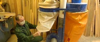
On the simplest models of serial drilling machines and on equipment that is made by hand, coordinate tables are installed mainly, which are driven mechanically.
If high precision and processing performance are required from a drilling machine, tables driven by electric motors are installed on it. Three types of gears are used in coordinate table drives:
- based on gears and racks;
- based on belt mechanisms;
- ball screw.
Helical rack and pinion transmission ensures positioning accuracy
The choice of transmission type is influenced by a number of parameters:
- the speed at which the table and the workpiece attached to it must move;
- power of the electric motor used;
- requirements for precision processing of parts.
High precision of movement is ensured by a ball screw drive, which also has a number of other advantages:
- very slight play;
- smooth movement;
- quiet operation;
- resistance to significant loads.
Ball screw in high precision coordinate table
The disadvantages of this type of transmission are the inability to ensure high speed of table movement and the significant cost of such a mechanism.
To reduce the cost of a homemade coordinate table for a drilling machine, you can equip it with a drive based on a conventional screw drive. However, in this case, care must be taken to ensure that the transmission screw mechanism is lubricated as often as possible.
Homemade coordinate table with screw gears and cylindrical guides
A budget option is also to use a drive for moving the coordinate table, made on the basis of a belt drive. When installing such a drive on a home-made coordinate table, you should take into account the disadvantages of using it:
- rapid wear of belts;
- stretching of belts during operation;
- increased risk of belt breakage under increased loads;
- low accuracy.
Accuracy and high speed of movement are ensured by coordinate table drives, made on the basis of a rack and pinion transmission. Meanwhile, when using such a drive, you should be prepared for the fact that play will form in the elements of its mechanism after a certain period of active use.
Guides
The guides along which the coordinate table moves are an important element of its design, since not only the smooth movement of the part, but also the accuracy of its processing depends on their quality and design features. Both in serial models and in homemade coordinate tables, the guides can be of rail or cylindrical type.
Smooth and accurate movement along the guides is ensured by the built-in carriage and bearing units. In cases where increased movement accuracy is required from the coordinate table, sliding bearings are used in its guides, since rolling bearings create significant play in the supports, although they reduce the friction force more effectively.
Bearing unit design
Guides for coordinate tables, depending on the type of carriage, are:
- equipped with an enlarged flange used to attach the structure to the bottom of the table;
- wafer-type, which are fastened in the usual way.
Dovetail guide
Step-by-step algorithm for manufacturing a household table with a mechanical drive
How to make a vacuum table for CNC with your own hands
To make a coordinate table with the simplest mechanical drive, you need to follow the instructions:
- It is necessary to make the central unit of the table in the form of a cross from metal profiles 20 x 20 cm (2 mm thick). It must ensure the stability of the entire structure, so all parts are welded.
- On the surface of the finished cross, assemble carriages with a stroke of 94 mm.
- File the profiles and then insert M10 nuts into them.
- Using M10 studs, assemble the handles with the bearing assembly.
- Next, you should weld two U-shaped bases from the corner, and then assemble the entire structure using bolts that were screwed into the previously pressed nuts.
- Wipe all components, as well as moving parts, with lubricant.
- The assembled table must be attached to the drilling machine bed.
To protect the lubricated structural elements from chips or other waste when processing the workpiece, it is advisable to lay plywood between the coordinate table and the machine. The dimensions of the finished manipulator will be 35 x 35 cm, and the thickness of the product will be 6.5 cm. It is desirable that the total length of the guides be about 30 cm.
Make the central unit of the table in the form of a cross
Assemble the carriages on the surface of the finished cross
File the profiles, insert the nuts
Assemble the handles with the bearing assembly on the studs
Weld two U-shaped bases from a corner
Assemble the entire structure
Wipe all components and moving parts with lubricant.
Attach to drill press bed
Useful tips
The instructions, which describe how to make a coordinate table with your own hands, explain the process step by step. However, minor problems may arise during operation. To avoid them, it is recommended to adhere to safety precautions and take into account the advice of experts. The most important of them:
- if you plan to process plastic or wood, then the base of the manipulator can be made of aluminum;
- with device dimensions of 35 x 35 cm, it is advisable to adjust the total length of the guides to 30 cm;
- to protect the device from chips before installation, it is recommended to place a piece of plywood under it;
- when using cylindrical guides, there is no possibility of connecting a lubrication supply system, so all parts must be lubricated manually;
- When assembling, it should be taken into account that the plain bearing provides better machining accuracy, while its counterpart (friction bearing) leads to some play.
Making a table for a laptop with a cooling system with your own hands
To carry out welding work, safety precautions must be observed. It involves the use of special clothing, a protective mask (shield), suede or tarpaulin gloves. The room in which the assembly is carried out must be ventilated or have a high-quality exhaust hood. When working outdoors, a canopy is required. Near the workplace, means and materials must be prepared to extinguish a possible fire.
The manufacture of a simple type coordinate manipulator can be mastered by a master with welding skills . It is not difficult to obtain a reliable and convenient product if you strictly follow the conditions of the drawing and the assembly algorithm. The home device allows you to engage in small-scale production of metal, wood, and plastic parts. The service life of such a device depends entirely on the quality of installation and the volume of drilling and milling work performed.
This is interesting: Design features of argon arc welding machines
Where is it profitable to buy a coordinate table?
How to make a table for a circular saw with your own hands?
We recommend buying a coordinate table at a good price in this Chinese store. Read more about how it can be successfully applied. Video of the youtube channel “Technician” at the end of the publication.
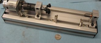
In this video review, there is a coordinate table that will become part of a milling machine. Made of aluminum alloy. Transverse stroke 50 mm, longitudinal 200. Do not pay attention to the play, it can be easily eliminated with a hexagon included. A standard M8 steel pin is used as lead screws. In addition to the dials, the marks on which are ordinary stickers, there is a ruler on the longitudinal movement. But there is no mark on the table by which you can keep a report.
The master disassembled the table to understand what we were dealing with. Where to buy, see at the beginning of the article. As you can see, the backlash is removed by pressing the plate. The lead screw rotates into bushings made of the same material. The table is a profile made of strong aluminum alloy with a wall thickness of 3 millimeters. There is no talk about working on steel, but we’ll try milling duralumin later.
Instead of a standard pin, which was tightened with a screwdriver, it was held in place by a shaft with a handle; now, thanks to the work of a turner, it was held in place by a wing screw. By screwing it all the way, the vertical movement is stopped. What you need for milling. Unscrew it a little more, the position of the shaft changes so that the handle does not interfere. Two bushings for the drill and router were also made. All that remains is to make a mount for the table and test it in operation.
Now drilling a 6 mm steel bar is a pleasure. Even 12 bolts for mounting on a Soviet machine table would be too small. Therefore, I had to screw 8 pins into pieces of steel pin. Now you can definitely fix the coordinate table and move on to the most important thing. To the test.
The first experimental material was a piece of acrylic plate. Its properties are slightly tougher than plexiglass. Not as sticky. To secure the part, there are two clamps included with the table. The minimum speed of the router is at 8000 rpm. No load is felt on the router, about 1 millimeter is removed. Continued in the video from the fifth minute
Add an adjustable end stop
1. To make the body of the stop stop J , cut two 51x73mm pieces from a 19mm thick board and glue them together face to face, aligning the ends and edges. When the glue is completely dry, cut a 6x5 mm groove in the middle of the back of the case (Fig. 5).
K to the specified dimensions and glue it using double-sided tape to the right side of the housing J (Fig. 5). Install a Forstner drill with a diameter of 13 mm into the chuck of the drilling machine and drill a 10 mm deep recess in the left side of the body, as shown in the figures and photo C. Then, without moving the parts, install a drill with a diameter of 6 mm and drill a through hole in the center of the recess through both parts.
3. Separate stopper K from body J. Using a Forstner drill with a diameter of 19 mm, drill 10 mm deep recesses in the stopper and body exactly above the 6 mm holes (Fig. 5). To align the centers before drilling, insert dowels with a diameter of 6 mm into the holes. Then, with a 7mm drill bit aligned in the middle of the 6mm slot on the back of the case, drill a through hole as shown in the picture.
(Photo C) - Secure the parts by placing the stopper K at the bottom and pressing the edge of the body J with the groove against the stop of the drill table. Drill a 13x10 mm countersink in the side face of the housing. (Photo D) - Secure the movable stopper K to the screw using washers and a nut, insert the screw into the housing hole J and screw it into the nut that is epoxy glued into the counterbore.
, secure the nut into the 13mm recess of the body J. Then cut out the slider L of the specified dimensions and glue it into the groove on the back side of the body, flush with its right edge (Fig. 5).
5. Apply a clear finish coat to all flying parts. After drying, place a wide 6mm washer on the button head screw and insert it into the hole in the stopper K. Place the second washer on the screw and then screw on the nut. Tighten the nut so that the stopper does not wobble, but the screw can rotate. Now connect the stopper to the body J (photo D ), turning the screw until both parts touch.
6. Using epoxy glue, secure the plastic knob nut to the end of the button head screw. Insert a hex head screw into the housing hole J at the back and add a washer and handwheel nut at the front (Figure 5). To use an adjustable end stop, first set the distance between the body and the stop to approximately 12 mm. Moving the slider with a hexagonal screw head in the guide aluminum profile, using a tape measure or measuring ruler, set the stopper at the required distance from the drill. Secure it by tightening the front handwheel nut. Now finely adjust the distance to the drill by rotating the side handwheel nut. The handwheel lock nut and L are located exactly in the center of the body, so you can use the adjustable stop to the right and left of the drill simply by flipping it over.
7. Assemble the clamps (Fig. 2). Insert the hex heads of their screws into the grooves of the aluminum profile guides. Now the drilling machine is ready for real work and can rightfully be called a carpentry machine.
Production of homemade versions
How to make a carpentry workbench with your own hands?
When manufacturing, you should initially select the material of manufacture:
- Cast iron is an expensive, heavy, brittle material. It is quite rarely used in the production of a drilling machine.
- Steel is a strong, hard, durable metal, which also has a fairly high cost. Steel can be called the most attractive material.
- Aluminum is a light, fusible, but expensive and soft material. It is quite easy to use in the manufacture of any machine parts. As a rule, mini equipment is created using this alloy.
The above materials are selected for a full or mini machine.
Do-it-yourself carpentry workbench: assembling the base
Before making a workbench from wood, it is better to estimate the amount of work in advance and outline the procedure. Most of the table parts are fixed using screw connections. To facilitate the assembly process, it is advisable to make holes for them in the plywood in advance in the appropriate places. For these purposes, you need to use a drill whose diameter is approximately 1/2 or 1/3 smaller than the diameter of the fastener itself.
Having prepared all the necessary tools and materials, as well as carefully studying the drawings of the carpentry workbench, you need to make all the structural parts. A circular saw is suitable for cutting wood and plywood. After this, the end part must be sanded so that the edges of all elements are smooth. This will not only simplify the assembly process, but will also avoid problems with joining parts.
To assemble the workbench base, you need to secure the frame and base plate.
First of all, the base is assembled. It consists of a base plate where a cabinet with drawers will be installed, an open area for equipment and stiffening ribs to strengthen the structure. To do this, you need to assemble the frame and fix the plate on it. For fixation, M50 fasteners should be used.
Note! Only dry lumber can be used for work. The optimal wood moisture content is 12%.
Hardware Definition
A coordinate table is a manipulator that is used to secure the workpiece being processed. There are several options for machine tables:
- vacuum fastening method - used quite rarely due to the complexity of the design;
- the mechanical type of fastening is simple to implement, you can do it yourself quickly;
- fastening due to the weight of the workpiece. When using a drilling machine, large workpieces can be processed. Due to its weight, the supported part remains in place even under strong impacts.
There are positioning with one, two, three degrees of freedom. This point determines that the workpiece can be fed along three different coordinates. When drilling a flat product, it is enough to move it along just one horizontal plane.
We can roughly distinguish two main types:
- Large dimensions. A large coordinate table is created taking into account the fact that the equipment itself, as well as the workpiece, will be installed on it.
- A coordinate table of small overall dimensions is mounted on the equipment frame.
There are several control mechanisms by which the coordinate table changes its position:
- Mechanical drive is quite common. You can make it for a drilling machine with your own hands to set up small-scale production.
- An electric drive is installed quite often for a drilling machine. Making it yourself is quite difficult, since you need to maintain high precision during manufacturing. For automatic movement, the coordinate table must have its own power source.
- Another separate group can be called a mechanism that operates using numerical control.
You can make a small coordinate table with a mechanical drive with your own hands.
Design selection
When choosing a design, you need to decide on its dimensions. If equipment that processes a part will be installed on a coordinate table, then its dimensions must be taken into account. If it is needed to fix the workpiece, it is mounted on the frame of the drilling equipment, and its width and length will be about 35 x 35 cm.
Tables are also distinguished by the type of fastening:
- When making a coordinate table with your own hands, the structure is equipped with a mechanical fastener. This is the simplest solution in terms of implementation, but it has a number of disadvantages. For example, it often leads to processing errors, and there is a risk of deformation of the product surface.
- Vacuum fastening is considered the best option. With its help, precise positioning of the workpiece on a horizontal plane is ensured. When an air stream is supplied into the gap between the tabletop and the workpiece, the pressure in this area changes. Thanks to this, it is possible to perform processing more efficiently (without mechanical damage to the product).
- Workpiece weight clamping is suitable when using a drill press to machine heavy parts. Due to its mass, the base product remains in the same place even with strong impact.
The functionality of the table depends on the number of degrees of freedom:
- If there is only one, then the workpiece can only be moved in one direction (this is a good option for processing flat products).
- If there are two degrees, it becomes possible to move the workpiece along X and Y coordinates.
- If there are three of them, then the part can move up, down and along the Z coordinate.
If the table is made for home production and processing of parts, then using two degrees of freedom is more than enough.
When making a coordinate table with your own hands, it is important to decide for what purpose it will be used. The parameters of the manipulator are selected in accordance with the dimensions, weight and shape of future workpieces. To work with various parts from metal and wood, a complex multifunctional mechanism is made. Usually, home craftsmen have enough capabilities of a small-sized table with mechanical fasteners and two degrees of freedom.
Mechanical
Vacuum
Fastening under the weight of the workpiece
Types of gears for table movement
With a small tabletop machine, the table is moved mechanically. But the greater the speed, accuracy and performance required, the more carefully the type of drive is selected. Electric motors are mainly used.
The essence of the unit’s operation is to convert the rotational work of the engine into translational motion of the table plane. There are three types of transmissions:
- rack and pinion;
- belt;
- ball screw.
The choice of node type is made based on:
- workpiece movement speed;
- machine engine power;
- required processing accuracy.
Machining accuracy at various transfer units
| Type of transmission mechanism | Accuracy Rate |
| Ball screw | 6-12 microns |
| Rack and pinion | up to 10 microns |
| Toothed belt | 50 … 100 µm |
Advantages of Ball Screw:
- possibility of high-precision processing;
- small backlash;
- smooth movement of the table;
- quiet operation;
- ability to take heavy loads.
Ball Screw Drawing
A significant disadvantage is the limited feed speed. The decrease in speed is especially noticeable when the propeller length is more than 1500 mm. Approximate speed calculation: for a 1 kW drive, the rotation speed is 3000 rpm. With a screw pitch of 10 mm, the transmission speed is 0.5 m/sec. In this case, 3 m will be covered in 6 seconds.
Another disadvantage is the high cost. You can reduce the cost of the project by using a connection with a screw and nut. In this case, it is necessary to ensure constant lubrication of the unit.
The rack and pinion transmission ensures high speed and sufficient accuracy. The disadvantage is the high degree of play when transmitting forces from the drive.
Installing a belt is the most budget-friendly and common method when creating a table with your own hands. The low cost of belt drive and feed speed up to 1 m/s is compensated by the following disadvantages:
- rapid wear;
- loss of tension due to stretching;
- possibility of breakage during acceleration;
- low accuracy of work.
When purchasing a coordinate table for drilling or do-it-yourself installation, you must take into account the working conditions. The ratio of all mechanisms in terms of parameters: workload, service life, heating and cooling will give a good result during operation
This is especially important when making it yourself from scrap materials.
Advantages and disadvantages of self-production
A coordinate table is an additional structure to a milling, drilling metal or woodworking machine. Thanks to it, you can increase equipment productivity by reducing the labor intensity of the parts processing process. The workpiece is simply fixed on the working surface and can move smoothly along a given path.
Homemade coordinate tables have the following advantages:
- small dimensions;
- simple design form;
- controlled mechanically;
- used in handicraft production.
Their main advantage is saving money. Making such a design from scratch will cost much less than buying a factory-made manipulator. Of course, there are a number of difficulties when making it yourself. A suitable drawing is needed, according to which the required trajectory of the workpiece will be set. If there is no someone else’s experience, then you will have to create it yourself, but any error when drawing a diagram will make itself felt during work. In addition, a homemade table is only suitable for small-scale production, since the simplest homemade mechanisms wear out much faster than factory ones.
Simple design form
Small dimensions
Mechanical control
Saving money
Product Description
An inversion table is used to treat a wide variety of spinal disorders. Moreover, with its help you can also strengthen the muscular corset and ligaments of the back.
An inversion table is a simulator that you can use independently and at home. Simply put, if you know the safety precautions and rules for performing exercises on it, you can use it without a trainer or supervision from doctors.
Inversion table DFC XJ
Despite the undoubted therapeutic effect provided by this simulator, it is not a panacea and in most cases is used only as an additional method of treatment to the main therapy. The reason is that it only improves the body’s compensatory functions and reduces the symptoms of diseases.
In addition, even in cases where the simulator is indicated for treatment (for example, with muscle tension or osteochondrosis), its use may be contraindicated in individual cases. Simply put, you should not use an inversion table without first consulting a doctor.
Purpose: what and where is it used?
An inversion table is used as an auxiliary treatment method for a relatively large number of diseases of the musculoskeletal system. In addition, its use is justified not only for the treatment of such diseases, but also for their prevention.
So the inversion table is used for:
treatment of degenerative diseases of the spine (for example, osteochondrosis); relieving excess tension in the muscles (here the device acts as a muscle relaxant); prevention of varicose veins, scoliosis, osteochondrosis; strengthening the muscle corset and ligamentous apparatus; increasing flexibility and, accordingly, range of motion; general relaxation and stress relief; stimulating microcirculation of blood in the back and the flow of lymphatic fluid.
Performing an exercise on an inversion table
Despite the possibility of preventing scoliosis with the help of an inversion table, using it if you already have scoliosis is not only pointless, but also dangerous. The fact is that those therapeutic exercises that are performed on such simulators are usually contraindicated for scoliotic disease.
The essence and advantages of application
The undoubted advantage of the inversion table is its autonomy. Simply put, the patient can perform various necessary exercises himself, without supervision from a doctor and at home.
In addition, a huge advantage of this simulator is that it can be made independently, and the process of manufacturing parts and subsequent assembly can be done even by a person inexperienced in such things.
All the necessary drawings and even video instructions for making an inversion table with your own hands can be easily found on the Internet.
If we talk about the therapeutic effect that an inversion table has, there is also a noticeable advantage of the device. The fact is that in case of inflammatory and dystrophic pathologies of the back, which are accompanied by pain, the exercise machine has a noticeable effect within 15 minutes of use.
Another advantage is that you can use an inversion table every day throughout your life, thereby reducing the risk of developing back diseases and eliminating symptoms (primarily pain) of existing diseases.
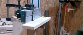
Homemade coordinate table, perhaps? — Homemade machines
Absolutely right, transverse and small longitudinal from a lathe, cast iron bed from a Komunaras drill with a screw feed, the working field turned out to be 300x300, mainly for processing small steel parts and is being invented, now everything is still in the process of experimentation and debugging, but there is positive experience with steel, It seems to cope with cutters up to 6 mm normally, but with a larger diameter problems begin (all mainly from using a 1200 W impact drill as a head), you need to come up with a tough, powerful head, when installing an angle grinder instead of a drill, you get a small grinder
Here’s a photo I took (though the quality is not very good) while working with steel, one has an x35 plate on it, the second photo shows the actual part for working with which the device was intended to work with (in the photo, one part is before processing, the second one, clamped in the chock, has already been passed through three times)
Modified on January 25, 2014 by BM_906