When performing welding work, it is very important to have high-quality and reliable wire feeding mechanisms on hand. The main advantages are that they make the work easier, since this functionality will ensure the supply of wire to the destination of the welding work.
For semi-automatic welding, such a feeding mechanism will act as a key unit and will simplify the work of even a professional welder. What are the advantages of this mechanism, what modern units exist today for drawing welding wire?
Types of devices
Depending on the method of feeding the welding wire, the mechanism can be:
- pushing;
- pulling;
- combined.
The pushing mechanisms together with the coil are located in the body of the welding machine or as a separate unit. This is the most common execution option.
Through a guide channel, it pushes the filler wire through the torch directly into the welding zone. Thanks to its location, it makes the welder's work easier.
The pulling mechanisms are located in the burner body. This allows you to work with longer guide channels. The disadvantage of this operating principle is the reduction in productivity and efficiency of the welder due to the heavier torch.
Combined devices combine both operating principles, but are extremely rare.
Depending on the thickness of the additive used, the feed mechanisms are two- or four-roller . For wire with a thickness of 1-1.2 mm, a two-roller mechanism with one drive and one clamp is usually used. For additives with a larger cross-section, two rollers of each type are used.
External feed mechanisms can be completely self-contained, portable or stationary. Modern devices are equipped with information panels. They allow you to monitor and adjust equipment parameters.
The device has an electronic control unit, which, if necessary, regulates the feed speed of the welding wire, which varies depending on the technology, working conditions and skills of the welder.
Some models have the ability to memorize welding modes. A cold drawing mode is provided, when the wire is fed into the welding zone without igniting the torch.
It is possible to purge the hose with shielding gas before starting welding work and when it is finished to remove dust and moisture.
Semi-automatic welding
This welding unit is a device with an incomplete automation cycle . The welding process takes place in an inert gas (argon), active gas (carbon dioxide) or a mixture of gases. The principle of welding is that in a semi-automatic machine, an electric arc produced by a direct electric current always burns between the product and the welding wire. During operation, gas passes through the torch to cover the welding zone, creating protection from air exposure. Such semi-automatic machines are good at working with sheet metal.
The semi-automatic machine allows you to significantly reduce operating time and increase the quality of welded joints. The popular model of semi-automatic welding machine MIG MAG works in conjunction with a welding wire pulling mechanism. The device must be located in the welding machine itself in its body or be remote and connected, if necessary, to a power source via a power cable.
The wire wound on a reel must be placed in a semi-automatic spool and then passed through the wire feed mechanism into a special channel. A welding torch is attached to it; gas is supplied from the cylinder to the torch through a specially attached tube. You can also use cored wire and in this case a gas cylinder will not be needed.
Operating principle
An ordinary feed mechanism consists of a DC electric motor, a reduction gear, a pressure and drive roller, a guide and an input channel. In addition, there is a lever with a spring and a screw that acts as a pressure regulator.
When voltage is applied to the electric motor, its shaft begins to rotate at a certain speed. On the same shaft with the electric motor there is a gearbox that reduces the number of revolutions to the required number.
The output shaft of the gearbox rotates the push/pull roller, which in turn pulls the welding wire pressed against it by the second roller. To eliminate slippage, there is an adjusting screw that acts on the pressure spring. It is necessary for a softer and more constant effect on the roller.
The feed mechanism in a semiautomatic welding machine may have a separate adjustment unit, activated from a button on the torch handle. Some models have replaceable bushings on the guide channels.
This allows you to reconfigure the equipment for different wire diameters. In addition, the mechanisms are designed with a valve and fitting for connecting water-cooled burners.
Some four-roller devices have an additional pair of rollers in front of the feed block. Their task is to level the additive. They are usually used when using flux-cored wire with a thickness of 0.8 mm to 4 mm.
Type and diameter of welding wire
The diameter of the roller groove is selected depending on the diameter and type of welding wire. The diameter and type of wire is written on the product itself - this is an alphanumeric engraving. When changing the wire section, you simply turn the roller over to the desired side and continue to use it further. Please note that the welding wire diameter marking indicates the groove that is closest to the marking.
On the PTK website, in the section about feed rollers, in the configured filters, you can easily select the desired roller by size, type and diameter of welding wire.
Popular models
Lincoln Electric produces a whole line of two- and four-roller mechanisms that feed welding wire. Don't forget about other brands.
LF-37, 38
Models LF-37, LF-38 are designed for use in conditions of high humidity and dust.
They work on 300mm (15kg) spools and can also use 200mm (5kg) spools. The wire can be solid or flux cored. There is a gas flow sensor which is useful when working with long cables. All settings are intuitive, after pressing the “select” button, 2/4 stroke modes are visible, you can adjust the pre-pull before starting work, hot and soft start (Hot/Soft) and crater filling are provided.
You can select the language to display information on the screen. The LF38 mechanism has a set of programs and a memory unit that provides recording of 10 modes of specified parameters.
The device has small dimensions and large indicators that display parameters during the welding process. Connection cables for liquid cooling are available. Can work with wire diameters from 0.6 mm to 1.6 mm. The manufacturer provides a 3-year warranty.
MSF 57
One of the best wire feeders for welding work is the MSF 57 from Kemppi.
The MSF 57 has four rollers. A wire cassette with a diameter of 300 mm is used. The quality of this feed mechanism is at a high level. This is perhaps the most reliable and convenient mechanism on the market based on user feedback.
Model MSF 57 with a power of 100 W is powered by 50 V. The welding wire can be fed into it at a speed of 0 to 25 m per minute.
The mechanism can work with stainless wire with a diameter from 0.6 mm to 1.6 mm, with flux-cored wire from 0.8 mm to 2.0 mm, with aluminum from 1.0 mm to 2.4 mm.
Fast and Furious MPTs02
The Forsage MPTs02 wire feeder from a Russian manufacturer has proven itself well. It has digital control of parameters, adjusts the wire feed speed in the range of 2-20 m/min.
The device has replaceable rollers, which allows you to quickly change to different diameters, and works with coils up to 300 mm. The mechanism provides for adjusting the gas purging time before welding from 0 to 0.5 s, after welding from 0 to 10 s. The gearbox power is 120 W.
Some craftsmen make semi-automatic welding inverters by adding a separate wire feed unit. But for the most part, they are unregulated feed mechanisms whose characteristics are significantly inferior to industrial designs.
When producing a complete analogue of a model, the cost of components will be significantly higher than the finished device.
How to properly thread the wire into the roller?
Correctly threading the welding wire into the feed roller is a guarantee of success when carrying out welding work; it also increases the productivity of semi-automatic welding machines and their service life.
Schematically in the figure we have shown the correct threading of the wire and possible errors that you may encounter.
- Normal clamping force.
- Excessive clamping force.
- Wire diameter too large.
- Wire diameter too small.
When threading the rollers with wire, take into account the recommendations for choosing the clamping force, which is adjusted using the adjusting screw on the feed mechanism of the welding machine.
| Type of welding wire | Clamping force | |
| Steel | 2,5–3,5 | |
| Aluminum | 1–2,5 | |
| Powder | 2–2,5 |
The range of PTK branded products includes a wide selection of feed rollers and related products; you can learn more about the technical characteristics, descriptions and photographs in the product cards. All products are available for order from sales managers and official dealers.
Feed rollers for cored wire
Article: 005.020.107 Feed roller 30x10x10 K 1.0–1.2
Feed roller for cored wire with a diameter of 1.0–1.2 mm. K-shaped groove. The dimensions of the roller are 30x10x10. Suitable for semi-automatic welding machines of the PTK MASTER MIG S, MASTER MIG F, MASTER MIG SYNERGY D and PTK RILON MIG GDM series.
Price: 629 RUR
Article: 005.040.124 Feed roller 30x22x10 K 0.8–0.9
Feed roller for cored wire with a diameter of 0.8–0.9 mm. K-shaped groove. The dimensions of the roller are 30x22x10. Suitable for PROFI semi-automatic welding machines MIG 300, MIG 350-1, MIG 350, MIG 500 from the HISTER factory and RILON MIG 250 GS, MIG 250 GDM, MIG 300 GDL, MIG 200 GW.
Price: 559 RUR
Article: 005.040.131 Feed roller 40x32x10 K 0.8–0.9
Feed roller for cored wire with a diameter of 0.8–0.9 mm. K-shaped groove. The dimensions of the roller are 40x32x10. Suitable for semi-automatic welding machines PTC RILON MIG 350 GF, MIG 500 GF, MIG 500 I, MIG 500 F, MIG 500 FW.
Price: 745 RUR
Article: 005.040.118 Feed roller 30x10x12 K 0.8–0.9
Feed roller for cored wire with a diameter of 0.8–0.9 mm. K-shaped groove. The dimensions of the roller are 30x10x12. Suitable for semi-automatic welding machines PROFI MIG 350, MIG 500 and PTK RILON MIG 250 P GDM, MIG 300 P GDL, MIG 300 GN, MIG 300 GD.
Price: 559 RUR
Article: 005.020.105 Feed roller 30x10x10 K 0.8–0.9
Feed roller for cored wire with a diameter of 0.8–0.9 mm. K-shaped groove. The dimensions of the roller are 30x10x10. Suitable for semi-automatic welding machines of the PTK MASTER MIG S, MASTER MIG F, MASTER MIG SYNERGY D and PTK RILON MIG GDM series.
Price: 629 RUR
Semi-automatic welding machine
Welding machines of this class are available in different modifications. The specific name, “semi-automatic”, means that you will have to perform certain actions yourself. However, special equipment makes it possible to simplify many operations, so using such equipment it is quite possible to create high-quality welded joints without assistants. Of course, this will require studying relevant technologies and acquiring sustainable practical skills.
Type of semi-automatic welding machine
Work principles
To connect parts using this method, heating the areas of future contact is used. The molten areas unite and, after lowering the temperature, form a strong solid unit. The following are issues that developers of relevant technologies pay attention to:
- The heating must be intense enough for the metal to begin to melt after processing.
- On the other hand, it is necessary to ensure only local impact so that the structure of neighboring areas is not damaged.
- You should also take into account the activation of oxidative processes and the possible penetration (into the area of molten metal) of impurities from the surrounding air. Such “additives” can worsen the strength and other initial parameters of materials.
The listed tasks are successfully solved by the welding machine. Heating in it is created by an electric arc. It is formed between the electrode and the metal surface when voltage is applied to them. Since a high current is used for a powerful continuous discharge, the relatively small-sized working spark gap quickly burns out. In order to avoid replacing it frequently, a thin wire is used, which is fed at the required speed into the work area. To eliminate the harmful influence of the environment, a neutral gas supply is also provided here.
Structure of a semi-automatic device
Equipment parts, their purpose and important features:
- Power supply. When creating an arc, a voltage of several tens of volts up to 200 amperes and more is generated. The power consumption of many production models is in the range from 5 to 6 kW. These figures are given in order to more accurately estimate the requirements for the power supply.
- Control devices are designed to adjust the wire feed speed and set the welding current level.
Signal indicators notify about connection to the network, the occurrence of critical operating modes and emergency situations.
- The wire for connection to the parts to be joined by welding is equipped with a special spring clamp.
- The burner is connected through a flexible hose to the body. There is a pipeline and hose running inside. They are designed for dosed supply of wire and gas into the work area.
- If the structure turns out to be heavy, then rotating wheels are installed in the bottom to move it.
- The wire wound on a reel is installed inside the housing. Its supply is carried out by pushing, pulling, or a combined drive.
View of a semiautomatic device with the housing cover removed
Technical specifications
Before finding out how much this or that semi-automatic welding machine costs, you need to determine the range of tasks that will have to be solved in practice. This will help you choose equipment that is not too expensive, but quite suitable in terms of its technical parameters.
Professional equipment is sometimes called equipment that is capable of providing current in excess of 300 A. In practice, such values are rarely required. For many experienced craftsmen working in automobile service centers, 200-250 A is quite enough.
A certain power reserve will not be superfluous. It will allow you to operate in nominal modes, without excessive loads, which will extend the service life of the equipment even with intensive use.
However, if a semi-automatic machine is intended to be used from time to time, to solve personal everyday problems, then such special requirements will be clearly unnecessary. But in any case, you need to study in more detail the technical characteristics of the equipment model you like.
The 220 V power supply is better suited for domestic use; you don’t have to look for a special power source. But professionals note the advantages of a three-phase 380 V network. As a rule, such wiring is better suited to increased loads. The use of three phases allows you to obtain a discharge with more stable parameters, which has a positive effect on the quality of welding.
Semi-automatic, which connects to a 220 V network
If you purchase a universal semi-automatic machine, it will be able to operate on 220 V, or 380 V with the appropriate connection. Permissible voltage deviations do not exceed 15-20%.
As the voltage decreases, power consumption and current will decrease.
The recommended rated current of the power supply must be checked. Its value can be 15-25 A. The wiring must be designed for the appropriate loads.
It is necessary to pay attention to the duration of constant switching on at maximum current. This parameter is indicated as a percentage. If it is equal to 60% at 180A, this means that at the highest permissible load the semi-automatic device can operate for 6 minutes, after which a four-minute break will be required to cool the equipment. The time intervals of the standard work cycle (10 min.) are determined in a similar way for other parameter values.
The following designations are used in the descriptions:
- MIG is an abbreviation for Metal Inert Gas. It determines that the equipment is intended for welding metals in argon, or other inert gas, or their mixtures in certain proportions. Consumables in this case are more expensive, but the weld is reliable even without additional protection.
- MAG is an acronym for Metal Active Gaz. This technology uses carbon dioxide protection. Compared to the first option, in this environment the quality of the weld is slightly worse. It is recommended to subsequently clean the created joint and coat it with anti-corrosion agents.
Overall dimensions and weight should also be studied carefully. When performing complex work in limited space, they will be of decisive importance.
What does a compact welding machine look like?
The length of the gas hose, return cable with clamp - these data are checked to determine the radius of the working area (when the device is installed permanently).
The range, step of change in operating voltage and welding current, the speed at which the wire is fed determine the possibility of using different welding modes, working with different metals, and the sizes of the parts being connected.
Maximum diameter of electrodes (tungsten, alkaline and others). Using this information and special tables, you can determine what thickness of products made from certain metals and alloys this machine is capable of welding.
Protection and insulation classes are important when performing work in rooms with high humidity or in other unfavorable and dangerous conditions.
If the efficiency factor is given, then it will be possible to evaluate the efficiency of the device’s use of energy resources. In modern high-quality models, this parameter reaches 85% or more.
Types of welding equipment
It is clear that the potential capabilities of this technology are largely determined by the parameters of the electrical power part. Previously, only circuits with transformer conversion of current and voltage were used. They provided the required result, but were characterized by large dimensions, insufficiently precise adjustment and maintenance of operating parameters.
These days, such engineering solutions are used less and less. Welding machines with frequency converters are more common.
A typical inverter works as follows:
- For power supply use a standard network (220 V, or 380 V (three phases) 50-60 Hz).
- The alternating current is rectified and filtering is used to remove the remaining ripple.
- Transistors and other electronic devices that perform the functions of switches convert the current into alternating current. But, compared to the original value, the frequency is increased many times, up to 40 - 55 kHz.
- At the next stage, the voltage is reduced to 20-80 V, which makes it possible to obtain a strong current (20 - 300 A) at the output of the welding machine, sufficient for welding procedures.
The inverter device is much more convenient and functional than its outdated analogues. It is significantly, several times, lighter. It can easily be moved by one person.
Experts appreciate the following advantages of this type of technology:
- The compact inverter welding machine can be carried using a shoulder strap. Its placement requires a minimum of space, so it becomes possible to carry out the most complex work procedures in cramped conditions.
- The development of production technologies and the reduction in cost of electronic components have reduced prices for equipment of this class. A high-quality inverter welding machine is inexpensive. It is quite accessible even for private users.
- The inverter is precisely tuned to work with a certain thickness and material of parts. In some models, the current is adjusted smoothly over a wide range. Such capabilities, when used correctly, allow you to obtain impeccable quality of the welded joint.
- The inverter welding machine maintains the set current value accurately. There will be no need for additional adjustments by the user, which also has a positive effect on the performance of work processes.
- A modern inverter semi-automatic device is well protected from voltage surges in the network. It is adapted to work in difficult conditions and retains its technical characteristics unchanged during long-term operation.
An inverter welding machine gets very hot, so this equipment is often equipped with fairly powerful forced air cooling systems. When constantly working in dusty rooms, preventive measures are regularly taken, carefully removing any contaminants that have gotten inside by removing the housing.
Inverter cooling must be quite efficient
Wire selection
Different values should be taken into account for wire made of steel, titanium, copper, other metals and alloys. Nowadays, more than 70 different modifications of products designed for various types of welding are produced. They are classified into the following main groups:
- MIG (MAG) welding wire, which has a solid structure and is designed to perform work operations in a protective gas environment.
- Hollow products with fillers. When used, they create local protection in the heating area.
- Wires for welding using argon arc technologies. They contain special additives
- Products that are intended for forming welded joints using flux.
Certain types of wires are created for welding low-alloy, high-strength, stainless and carbon steels, copper, cast iron, nickel and aluminum products. In the standard designation, the first group of numbers indicates the percentage of carbon (“09” is 0.08%). The smaller the parameter, the higher the ductility of the wire.
Wire for welding machines, ready for installation, on special reels
A semi-automatic welding machine operating with currents up to 200-250A inclusive is equipped with feed mechanisms designed for wire with a diameter of 0.6 to 1 mm. As power increases, technicians install the appropriate equipment.
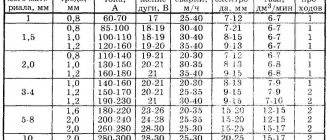
Technical and performance parameters that must be used in practice for calculations and adjustments
Wire diameter, mm Thickness of metal parts, mm Voltage between the electrode and the welding area, V Welding current (range in A) Shielding gas supply rate, l per min Speed of weld creation, m per hour of continuous operation
| 0,6 | 0,5-1,5 | 16-20 | 40-100 | 6-7 | 25-35 |
| 0,8 | 0,8-2,5 | 17-25 | 50-180 | 7-12 | 22-32 |
| 1 | 1,0-4,0 | 18-28 | 60-250 | 8-16 | 20-30 |
| 1,2 | 1,5-8,0 | 18-32 | 70-350 | 9-20 | 18-28 |
| 1,6 | 2,0-20 | 20-36 | 100-500 | 10-22 | 16-25 |
Setting up the welding machine when using wire with a certain diameter
Wire diameter, mm Voltage between the electrode and the welding area, V Welding current (range in A) Distance in mm from the welding area to the torch nozzle Electrode extension in mm
| 0,6 | 16-20 | 40-100 | From 5 to 15 | From 6 to 10 |
| 0,8 | 17-25 | 50-180 | From 5 to 15 | From 8 to 12 |
| 1 | 18-28 | 60-250 | From 8 to 18 | From 8 to 14 |
| 1,2 | 18-32 | 70-350 | From 8 to 16 | From 10 to 15 |
| 1,6 | 20-36 | 100-500 | From 15 to 25 | From 14 to 25 |
As a standard, a welding machine of this type is equipped to work with steel wires of the above standard sizes. But if it is intended to weld aluminum products in an argon environment, then special feed mechanisms are used, designed for a relatively large wire diameter and low strength.
For uniform advancement, the tips are coated on the inside with Teflon and other materials that provide a low coefficient of friction.
Flux-cored wire contains special additives. When an electric arc and high temperature are formed, they evaporate, creating a protective environment in the welding working area. This solution eliminates the need to use inert gas. With its help, you can do away with heavy cylinders, eliminating the worries and costs associated with the use of these containers. They must be transported and stored under special conditions and additional safety measures must be observed during operation. You will need to spend time and money on the recertification procedure.
Types of wires with fillers
Cored wires provide less reliable and uniform protection. They quickly pollute the atmosphere with harmful compounds, so their use in enclosed spaces is limited.
Welding using a semi-automatic machine
This technology differs significantly when working with different metals, shapes and thicknesses of parts. The following is an algorithm for the main actions and features that experienced craftsmen take into account in the process of welding aluminum products.
What does semi-automatic welding look like?
This metal is characterized by low density, low strength, high electrical and thermal conductivity. It melts at + 660 °C, and a film of oxides, which very quickly forms on the surface, at temperatures above + 2000 °C. The given data defines the basic conditions for high-quality welding:
- With high thermal conductivity, it is necessary to use high current and a short distance from the electrode to the products being connected. This can be provided by a semi-automatic inverter welding machine.
- Such a device is useful for accurately setting the optimal current strength, because aluminum parts can be quickly burned through.
- Even an experienced specialist will not be able to ensure that a crater does not form on the weld. A semi-automatic machine is also well suited for eliminating such defects.
Welding of aluminum parts is performed as follows:
- They ensure the absence of pollution in the room atmosphere, maintain air temperature in the range from + 18°C to + 22°C with a humidity of no more than 65-70%.
- Remove mechanically and with the help of special chemicals oxides, fats and other contaminants from surfaces.
- The protective environment is created with gas - argon. Select the wire and set the modes that correspond to the parameters of the elements being connected.
- When performing work, use a mask, gloves, and other personal protective equipment.
Video. Semi-automatic test
Modern semi-automatic machines are easier to set up. They have control units with built-in different operating modes. After entering the initial data, the optimal current strength and other parameters will be set. However, much depends on the skill of the performer. That is why, to obtain a high-quality and reliable welding connection, you need not only the most advanced apparatus, but also training that will help you accumulate the necessary practical experience.
elquanta.ru
Feeding device for the inverter, and how to feed wire into the welding zone
Just 15-20 years ago, working as a welder was labor-intensive and difficult. Welders used large and inconvenient transformers weighing more than 80 kg for their work. The device was equipped with special transportation loops for more convenient movement around the workshop or to the place of welding work. During transportation, special platforms were used. When working at height, it was necessary to feed them with a truck crane. This made the work of the welder and the people around him more difficult.
Inverter
But progress does not stand still and now there are compact inverter welding machines the size of a small box and weighing up to 15 kg. The inverter device works on the principle of rectifying and converting the input network voltage, using special resistors, into a current with a large switching amplitude, then it is reduced to the operating current. The main advantage is that efficiency is achieved up to 90% with small sizes and low weight up to 15 kg. There is also a smooth current setting, which is typical for welding thin metal.
Inverter machines can work both for welding with simple electrodes (MMA) and, together with a feed mechanism, act as a source for semi-automatic welding (MIG).
Nowadays, most inverters support welding modes such as coated electrodes (MMA), refractory tungsten electrodes in argon (TIG), and semi-automatic welding (MAG). They have a welding switch on the control panel, which selects a specific welding method.
Let's take a closer look at what a feed mechanism is and the advantages over welding with simple electrodes.
Feeding mechanism is a set of electromechanical devices that ensure automatic and uninterrupted supply of welding wire and shielding gas to the welding zone.
Feeder
Let's take a closer look at what the feeding mechanism consists of:
- Welding sleeve. It is a flexible frame hose covered with multilayer rubber to protect and insulate the power cable. Inside there is a special steel spiral channel for feeding the welding wire to the welding site. The hose also provides a supply of shielding gas to protect the weld pool from the environment. Near the welding torch there is a button to turn on the wire and gas feed mechanism.
- Wire feed mechanism. Ensures uninterrupted wire feed through the welding hose. It consists of a direct or alternating current electric motor, a clamping device for pressing the rollers using screw clamps with a certain force.
- Device for installing a cassette with welding wire. It is located near the feed mechanism and is designed to provide the welding arc with filler material for a long time. The cassette can be positioned both vertically and horizontally relative to the feeding mechanism. The cassette is secured using a special nut or clamps.
- Control unit. It is used to adjust the wire feed. The adjustment can be electronic using a rheostat or more coarse thanks to interchangeable gears. Modern ones are equipped with digital displays, on which you can accurately set the welding speed and thereby ensure better seam formation.
The main advantages over welding with electrodes are a faster welding process, there is no need to change the electrode often, and better control over the welding process. The disadvantages are the fear of drafts and strong winds (possible formation of pores), and the connection to the source of protective gas (cylinder, ramp).
How to connect the feeder to the inverter?
To connect the feeder you will need:
- screwdriver figured;
- soldering iron with a power of 50 watts;
- rosin;
- solder;
- drill with a drill bit for drilling out rivets;
- pliers.
Before starting the operation, make sure that the device is not connected to the network!
So, after making sure that the inverter is de-energized, remove the protective cover. To do this, take a shaped screwdriver and unscrew 4 screws on each side on the side walls. Next, take a drill with a small drill and drill out the rivets that secure the plug to the back wall of the device. After removing the plug, feed wires with a three-pin connector through this hole and turn on the soldering iron. While it warms up, carefully peel off the protective layer of varnish from the capacitor located in the middle along the board, as well as from the track in the middle and from the metal hole.
After everything is done, solder the wires securely and carefully according to the instructions included with the device. Next, we take rivets and pliers and secure the 3-pin socket with wires that are soldered to the back wall of the case. When everything is done, put the cover back in place and screw the screws back on.
Don’t forget to get a cylinder with protective gas, a reducer for adjusting the gas supply, 10-15 meters of hoses for connecting the reducer and the device, and a coil of welding wire. That's all, all you have to do is connect everything and your semi-automatic welding is ready.
- Author: Alexander Romanovich Chernyshov
stanok.guru
Feed rollers for steel wire
Article: 005.040.120 Feed roller 30x22x10 V 0.6–0.8
Feed roller for steel wire with a diameter of 0.6–0.8 mm. V-shaped groove. The dimensions of the roller are 30x22x10. Suitable for PROFI semi-automatic welding machines MIG 200, MIG 250, MIG 300, MIG 350-1, MIG 350, MIG 500 from the HISTER factory and RILON PTK MIG 250 GS, MIG 250 GDM, MIG 300 Y, MIG 200 GW, MIG 300 GW , MIG 300 GDL.
Price: 559 RUR
Article: 005.040.127 Feed roller 40x32x10 V 1.0–1.2
Feed roller for steel wire with a diameter of 1.0–1.2 mm. V-shaped groove. The dimensions of the roller are 40x32x10. Suitable for semi-automatic welding machines PTC RILON MIG 350 GF, MIG 500 GF, MIG 500 I, MIG 500 F, MIG 500 FW.
Price: 675 RUR
Article: 005.040.109 Feed roller 40x32x10 V 1.2–1.6
Feed roller for steel wire with a diameter of 1.2–1.6 mm. V-shaped groove. The dimensions of the roller are 40x32x10. Suitable for semi-automatic welding machines PTC RILON MIG 350 GF, MIG 500 GF, MIG 500 I, MIG 500 F, MIG 500 FW.
Price: 675 RUR
Article: 005.040.108 Feeding roller 40x32x10 V 0.8-1.0
Feed roller for steel wire with a diameter of 0.8–1.0 mm. V-shaped groove. The dimensions of the roller are 40x32x10. Suitable for semi-automatic welding machines PTC RILON MIG 350 GF, MIG 500 GF, MIG 500 I, MIG 500 F, MIG 500 FW.
Price: 675 RUR
Article: 005.040.107 Feed roller 30x22x10 V 1.2–1.6
Feed roller for steel wire with a diameter of 1.2–1.6 mm. V-shaped groove. The dimensions of the roller are 30x22x10. Suitable for semi-automatic welding machines PROFI MIG 350-1, MIG 350, MIG 500 from the HISTER factory.
Price: 559 RUR
Article: 005.040.105 Feed roller 30x22x10 V 1.0–1.2
Feed roller for steel wire with a diameter of 1.0–1.2 mm. V-shaped groove. The dimensions of the roller are 30x22x10. Suitable for PROFI semi-automatic welding machines MIG 200, MIG 250, MIG 300, MIG 350-1, MIG 350, MIG 500 from the HISTER factory and RILON PTK MIG 250 GDM, MIG 300 Y, MIG 250 GW, MIG 300 GW, MIG 300 GDL .
Price: 559 RUR
Article: 005.040.106 Feed roller 30x22x10 V 0.8–1.0
Feed roller for steel wire with a diameter of 0.8–1.0 mm. V-shaped groove. The dimensions of the roller are 30x22x10. Suitable for PROFI semi-automatic welding machines MIG 200, MIG 250, MIG 300, MIG 350-1, MIG 350, MIG 500 from the HISTER factory and RILON PTK MIG 250 GS, MIG 250 GDM, MIG 300 Y, MIG 200 GW, MIG 250 GW , MIG 300 GW, MIG 300 GDL.
Price: 559 RUR
Article: 005.040.101 Feed roller 30x10x12 V 0.8–1.0
Feed roller for steel wire with a diameter of 0.8–1.0 mm. V-shaped groove. The dimensions of the roller are 30x10x12. Suitable for semi-automatic welding machines PROFI MIG 350, MIG 500 and PTK RILON MIG 250 P GDM, MIG 300 P GDL, MIG 300 GN, MIG 300 GD.
Price: 559 RUR
Article: 005.040.102 Feed roller 30x10x12 V 1.0–1.2
Feed roller for steel wire with a diameter of 1.0–1.2 mm. V-shaped groove. The dimensions of the roller are 30x10x12. Suitable for semi-automatic welding machines PROFI MIG 350, MIG 500 and PTK RILON MIG 250 P GDM, MIG 300 P GDL, MIG 300 GN, MIG 300 GD.
Price: 559 RUR
Article: 005.040.103 Feed roller 30x10x12 V 1.2–1.6
Feed roller for steel wire with a diameter of 1.2–1.6 mm. V-shaped groove. The dimensions of the roller are 30x10x12. Suitable for PROFI semi-automatic welding machines MIG 350, MIG 500.
Price: 559 RUR
Article: 005.040.113 Feed roller 35x25x8 V 1.0–1.2
Feed roller for steel wire with a diameter of 1.0–1.2 mm. V-shaped groove. The dimensions of the roller are 35x25x8. Suitable for semi-automatic welding machines PROFI MIG 200, MIG 250.
Price: 585 RUR
Article: 005.040.112 Feed roller 35x25x8 V 0.8–1.0
Feed roller for steel wire with a diameter of 0.8–1.0 mm. V-shaped groove. The dimensions of the roller are 35x25x8. Suitable for semi-automatic welding machines PROFI MIG 200, MIG 250.
Price: 585 RUR
Article: 005.020.102 Feed roller 30x10x10 V 0.6–0.8
Feed roller for steel wire with a diameter of 0.6–0.8 mm. V-shaped groove. The dimensions of the roller are 30x10x10. Suitable for semi-automatic welding machines of the PTK MASTER MIG S, MASTER MIG F, MASTER MIG SYNERGY D and PTK RILON MIG GDM series.
Price: 629 RUR
Article: 005.020.103 Feed roller 30x10x10 V 0.8–1.0
Feed roller for steel wire with a diameter of 0.8–1.0 mm. V-shaped groove. The dimensions of the roller are 30x10x10. Suitable for semi-automatic welding machines of the PTK MASTER MIG S, MASTER MIG F, MASTER MIG SYNERGY D and PTK RILON MIG GDM series.
Price: 629 RUR
Do-it-yourself semi-automatic welding machine: how to make it, diagram and all the details
A unit designed for welding products is considered to be a semi-automatic welding machine. Such devices can come in various types and shapes. But the most important thing is the inverter mechanism.
It is necessary that it be of high quality, multifunctional and safe for the consumer. Most professional welders do not trust Chinese products and make the devices themselves.
The manufacturing scheme for homemade inverters is quite simple. It is important to consider for what purposes the device will be manufactured.
There are inverters for:
- Welding using flux-cored wire;
- Welding with various gases;
- Welding under a thick layer of flux;
Sometimes, to achieve a high-quality result and obtain an even weld, the interaction of two devices is necessary.
Inverter devices are also divided into:
- Single-hull;
- Double-hull;
- Pushing;
- Pulling;
- Stationary;
- Mobile, which includes a trolley;
- Portable;
- Designed for beginner welders;
- Designed for semi-professional welders;
- Designed for professional craftsmen;
Inverter circuit:
Principle of operation
The operating principle of the inverter includes:
- Adjusting and moving the burner;
- Control and monitoring of the welding process;
When the unit is connected to the electrical network, a conversion of alternating current to direct current is observed. For this procedure you will need an electronic module, special rectifiers and a high-frequency transformer.
For high-quality welding, it is necessary that the future unit has parameters such as the feed speed of the special wire, current strength and voltage in identical balance. For these characteristics, you will need an arc power source that has current-voltage readings.
The length of the arc must be determined by the specified voltage. The wire feed speed directly depends on the welding current.
Homemade device diagram:
The electrical circuit of the device provides for the fact that the type of welding greatly influences the progressive performance of the devices as a whole.
Electrical diagram of a homemade device:
DIY semi-automatic - detailed video
Created plan
Any scheme of a homemade device provides a separate sequence of operation: