A steady rest is an additional device for a machine that acts as a main or secondary support when working with workpieces. The device is often used to provide stability to workpieces and avoid damage or deformation. There are several types of steady rest for a lathe, each of which has its own effect on the processing of workpieces. In this article we will analyze all the functionality of this device, its advantages and disadvantages.
How to make it yourself
Homemade designs allow you to reduce the cost of lathe equipment.
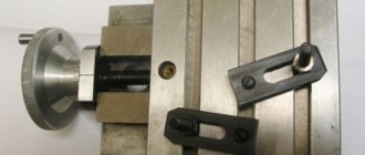
You can offer an option based on a flange for a pipe connection (diameter: external - 20 cm, internal - 11 cm). 3 studs 15 cm long and with M14 thread are used as cams. A handle is formed on top of them, and a bronze cap with a hole with a diameter of 14 mm is fixed at the bottom.
The flange is marked into 3 sectors (120 degrees each). According to the markings, holes are drilled towards the center of the circle. For adjustment, M14 nuts are welded into which studs are screwed.
The base for attaching to the machine is made from a 100 mm angle (steel thickness is at least 10 mm). It is welded to the flange.
Holes are made in the base to secure the fixture to a standard machine head mounting plate.
Design options for homemade lunettes
A steady rest for a lathe is not cheap, so there is little point in buying one if the device is not used very often. It’s easier then to make a steady rest with your own hands. For example, for the IZh1 lathe, you can implement a homemade product using the following design:
- A flange for connecting pipes is used as the base where the cams will be fixed. The flange size is 200 mm in outer diameter and 110 mm in inner diameter. Using a protractor, the flange is divided with a marker into three equal sectors with an angle of 120 degrees each. The sector connection lines will be exactly the places where you need to secure the cam feed mechanisms.
- Instead of cams, you can use three studs with 14 threads and a length of 150 mm each. Handles are welded onto the studs from one end (pieces of wire 8 mm in diameter and 30 mm long, so that it looks like the letter “T” in shape); on the other end, three bronze pointed caps with an internal thread diameter of 14 are ordered from a turner.
- The mechanism for adjusting and fixing the cams can be made from three nuts with an internal thread of 14 (for each cam), two of which are welded opposite each other along lines pre-drawn on the flange.
- To attach the turning rest to the bed, it is necessary to make a special substrate that could move along the runners and be fixed in a certain place. The substrate can be made from a steel angle with a metal thickness of at least 10 mm and a shelf size of 100 mm. The length of the angle should be equal to the width of the frame runners and cover the guides. In order for the shelf to move strictly along the guides, two pieces of 100 mm in length are cut from corners with shelves measuring 15 mm each and a metal thickness of 2 mm. They are placed on runners (opposite each other), and a large corner is placed on top of them, which is secured by welding.
- Next, a hole of 12 is drilled in the main corner so that the substrate can be bolted to a standard metal plate from the lathe headstock mount. The flange is fixed in the headstock, positioned so that one pair of welded nuts looks vertically upward, the corner on the slide is moved close to the flange and welded to it.
- The lunette is removed from the headstock, one nut is screwed onto each cam, an engraver is put on and the cams are screwed into the pre-welded nuts. After this, bronze “caps” are screwed onto the ends of the cams.
The homemade steady rest is ready for use. Pre-tightened nuts with engravers serve as clamps when setting the cams to the required position.
Everyone who is in the subject, support the discussion in the comments! Perhaps you have other interesting designs for making lathe steady rests with your own hands!
Old Soviet models of wood and metal machines
Soviet equipment is still in use in production. Some people fundamentally prefer to equip their home workshops with units from the USSR.
Important!
It is sometimes difficult to find equipment or components for Soviet equipment in case of breakdown.
Screw-cutting lathe IT-1M
The lightweight machine was intended for gaining practice in workshops. Allows you to process cylindrical workpieces from the outside, drill and boring, and cut threads. Currently out of production.
Screw-cutting lathe TV-6
Appeared on the market in the 80s. It is mainly used for training future turners in workshops and training centers. Allows you to perform basic operations.
Characteristics:
- Spindle diameter - 12 mm.
- Spindle speed - 130-170 rpm.
- The distance between centers is 350 mm.
- The maximum processing length is 300 mm.
Lathes Universal 2 and Universal 3
Tabletop machines for the production of small parts. Most turning jobs are possible. The maximum diameter and length of the workpiece is 12.5 cm and 18 cm.
Lathe TSH-3
Performs the function of a sharpening and grinding unit. Suitable for use in home workshop and industrial purposes. In addition to classical turning work, the unit is suitable for finishing grinding of products and sharpening cutting and metalworking tools.
1E61M, 1E61PM, 1E61VM screw-cutting lathes
Refers to special machines that provide higher processing accuracy. All three modifications belong to the turning-screw-cutting group with a height above the centers of 175 mm.
The diameter of the processed rod does not exceed 32 mm. The maximum movement distance of the caliper is 200 mm.
Screw-cutting lathe 1М63Н
Multifunctional unit designed to perform all types of turning operations. This model also allows you to work with conical surfaces and cut multi-start threads.
The letter H in the marking indicates the ability to obtain dimensions of normal accuracy. It is possible to install additional equipment when working with large-sized workpieces.
Turret lathe 1341
The turret group machine allows processing using several tools at the same time. Available operations:
- Treatment of external and internal surfaces.
- Thread cutting.
- Drilling, countersinking, reaming.
- Working with shaped surfaces.
Processing is performed in automatic and semi-automatic mode. It is possible to produce parts from rods and piece blanks.
Screw-cutting lathe 1N65
An improved modification of the 1M65 unit. It is possible to process cylindrical and conical parts, as well as complex shaped surfaces.
Specifications:
- The height of the center above the bed and support is 500 and 325 mm.
- Spindle diameter - 128 mm.
- The maximum weight of the workpiece is 5 tons.
- The maximum diameter of the workpiece in the jaws is 870 mm.
Screw-cutting lathe 1M63
Developed in the 50s for processing workpieces made of various metals. At that time, it was a unit with unique characteristics, and it was purchased by large industrial enterprises. It ensured high quality and precision processing when turning products of any complexity.
Screw-cutting lathe 1A616
The unit was produced in the 50s of the last century. In that era, the technical characteristics were among the best. The machine is successfully used in many enterprises to this day.
The equipment is designed for a wide range of work with small workpieces. The letter A indicates particularly high processing accuracy. It is possible to cut modular, inch, and pitch threads without restructuring the kinematics.
School lathe TV-4
Developed for teaching turning in school workshops and training centers. A universal machine suitable for basic turning operations. It is lightweight and small in size, which is why it is popular in home workshops.
Metal lathe Shkolnik TV-7
The machine is manually controlled, designed for processing workpieces 100-300 mm. Supports four speed modes. Allows you to perform basic operations - external turning, boring, cutting metric threads, end processing, drilling holes. Purpose - practical training of future turners.
Tabletop metal lathe TV-16
A machine with small dimensions for performing operations of medium complexity. Available for hole drilling, thread cutting, external turning, boring.
Options:
- The distance between centers is 250 mm.
- The maximum diameter of the workpiece above the bed is 160 mm.
- The spindle hole diameter is 18 mm.
- Power - 0.4-0.5 kW.
Types of steady rests for lathes
Steady rests for lathes come in different types. In addition to differences in structural elements, sizes, types of mounting on the frame, all tools without exception can be classified into one of two main categories:
- Lathe lunettes, which are called stationary. They are installed permanently at any working point and remain there during the entire processing cycle.
- Devices that are called movable. Their location on the bed changes depending on where the turning tool moves along the workpiece.
Steady rests for a grinding machine have a similar design to the stationary fixtures of a lathe. Their supporting parts are coated with a material that does not allow the grooves on the workpiece to be wiped, such as babbitt.
Fixed lunette
A fixed steady rest is a device for a lathe, the purpose of which is to support a long workpiece. This allows for more precise processing of the product and eliminates vibration. The method of attaching the equipment to the frame is through a flat base plate and a bolted connection. A characteristic feature of all fixed turning steady rests is the presence of three rollers, or cams, two of which support the part from below, the third provides support from above. In order to install the workpiece on the fixture, the upper part of the latter can be hinged, and after securing the part, it returns to its place and is fixed with a special bolt. The design of fixed turning equipment fully corresponds to the design described in the section “Design and purpose of the steady rest.”
Lunette of movable design
A movable steady rest is a slightly different support design than a fixed device. It is no longer attached to the frame, but to a longitudinal support on a lathe. This allows the system to move simultaneously and in the direction in which the cutting tool is moving. That is, it is located opposite the incisor itself. The main purpose of a movable turning rest is to eliminate bending of thin and long parts under the influence of a cutter. This allows you to avoid jamming of the tool and damage to the product. The movable turning device has the following structural elements:
- Base with mounting holes. This is an all-metal element that is shaped like a question mark. There is no need for a folding part, as with a fixed lathe rest, since the part can easily be inserted into the fixture from the side.
- Support cams, of which there are two. One is located on top, the other on the side. The third support here is the cutter itself.
- Screws for extending and securing the jaws.
Using a steady rest
If a steady rest is installed on the machine, the operator must comply with a number of mandatory requirements:
- More carefully control the alignment of the centers of the tailstock and front stock.
- Since the rest of a lathe is most often needed when performing operations such as thread cutting, after each cycle it is necessary to remove all the resulting burrs and chips.
- A stationary steady rest should be secured not only with a T-shaped nut in the grooves, but also with an adjustment screw: it is this that eliminates possible deflection of the steady rest base when processing massive workpieces.
- For movable versions, it is worth checking the movement of the steady rest at idle speed of the machine, monitoring the ease of sliding.
The operational advantage of the movable rest is that it slides along the top of the follower base, allowing the tool holder to be moved and removed while maintaining pressure on the stop. For example, the steady rest for 1K62 provides thread cutting and even fine turning for workpieces of small diameters.
Machining parts in steady rests
Long and thin parts, the length of which is 10-12 times greater than the diameter, bend during turning under the influence of their own weight and cutting forces, as a result of which they receive a barrel-shaped shape - thicker in the middle and thinner at the ends. This can be avoided by using a special support device - rests. When using steady rests, you can grind parts by removing chips of a larger cross-section, without fear of their deflection.
Lunettes can be fixed or movable.
Fixed rest
The fixed steady rest (Fig. 339) consists of a cast iron body 1, to which a hinged cover 6 is attached using a bolt 7, which makes installation of the part easier. The base of the body of the steady rest is shaped according to the guides of the frame, on which it is secured with a bar 9 and a bolt 8. Two cams 4 are moved in the body using adjusting bolts 2, and one cam 5 is moved in the cover. Screws 3 are used to secure the cams in the required position. The device allows you to install shafts of various diameters into the steady rest.
Rice. 339. Fixed steady rest
Before installing the workpiece into the steady rest, you need to machine a groove in the middle for the cams, a width slightly larger than the width of the cam (Fig. 340). If the workpiece has a large length and a small diameter, then when turning such a groove, deflection of the workpiece itself is inevitable. To avoid this, first machine an additional groove closer to the end of the workpiece and, having installed a steady rest in it, machine the main groove in the middle.
Fig. 340. Turning a part using a fixed steady rest
Sometimes the workpiece can be so long and thin that one main groove is not enough. In such cases, two or more additional grooves are machined.
Machining in a steady rest
Processing in a steady rest is carried out as follows: grind the part to the groove, i.e., to the place where the steady rest is located, then turn the part over, install it again in the centers and, again securing it in the steady rest, grind the rest of the shaft.
In some cases it is not practical to grind additional grooves; then apply the method shown in Fig. 341 and 342. Cylindrical bushing 2 (Fig. 342) is put on the middle part of the workpiece 1 and, using bolts 4, is installed concentrically with the axis of the workpiece. The concentricity of the bushing is checked with indicator 3, as shown in Fig. 342.
The workpiece with the sleeve in place is installed in the steady rest (Fig. 341), and the ends are placed in the centers and ground to the steady rest. After this, the steady rest is opened, the workpiece is removed from the centers and the sleeve is removed. Then the workpiece is turned over and, having installed the cams of the steady rest along the diameter of the turned part, the remaining section of the workpiece is turned.
Fixed steady rests are also used for cutting ends and trimming the ends of long parts. In Fig. 343 shows the use of a stationary rest when cutting the end: the part is fixed at one end in a three-jaw chuck, and the other is installed in the rest.
Rice. 342. Checking the concentricity of the installation of the bushing for processing a part in a stationary rest
Fig. 341. Turning a part with a bushing in a stationary rest
In the same way, you can machine precise holes from the end of a long part, for example, bore a conical hole in the spindle of a lathe or drill such a part along its entire length.
The cams of the fixed steady rest must be installed exactly along the diameter of the part with the center on the spindle axis; they should not be clamped tightly. Surface of the part supported
Rice. 343. Trimming the end of a part installed in a chuck and a fixed rest
Rice. 344. Fixed steady rest with ball bearings for high-speed processing
cams, it is necessary to lubricate with oil to reduce friction and prevent the formation of scoring.
Steady rests with hard jaws are not suitable for high-speed machining due to rapid wear of the jaws.
Rice. 345 Turning a part using a movable steady rest
For high-speed processing, steady rests with roller or ball bearings are used (Fig. 344)
In this case, sliding friction is replaced by rolling friction, which reduces the heating of the workpiece, which is important when working at high cutting speeds
Movable steady rest
The movable steady rest (Fig. 345) is fixed to the caliper carriage. Together with it, following the cutter, it moves along the part being turned and supports it at the point where the force is applied, protecting it from deflection. A movable steady rest is used for finishing turning of long parts. It has only two cams. They are pulled out and secured in the same way as the cams of a fixed rest.
Installation and processing using steady rests
When installing workpieces in which the length of the protruding part from the chuck is more than 10 diameters ( L / D
rests
are used as additional support (Fig. 1.26).
Fixed rest
(Fig. 1.26
a
) are installed on the guides of the machine bed and secured with a bar 5 using a bolt and nut 6. The upper part
1
of the fixed steady rest is folding, which allows you to remove and install workpieces on the cams or rollers
4
of the steady rest, which serve as a support for the workpiece being processed and are pressed to the part with screws
2
; After installing the workpiece, screws 2 are fixed with bolts 3.
A groove is machined on the workpiece, in the places where the steady rest rollers are installed. The groove is usually performed in the middle of the workpiece.
a ) b )
V)
Figure 1.26. Lunettes:
A
) motionless;
b
) mobile;
c
) fixed with ball bearings
Movable steady rest
(Fig. 1.2
6
) is mounted on the support carriage and moves along the part during processing. The movable steady rest has two cams that serve as supports for the workpiece. The third support is the cutter.
For high-speed processing, fixed steady rests with ball bearings on the cams are used (Fig. 1.26 c
).
When turning, long and thin parts bend under the influence of their own weight and cutting forces, as a result of which they get a barrel-shaped shape. This can be avoided by using a steady rest (Fig. 1.27).
Before installing the workpiece into the steady rest, you need to machine a groove in the middle for the cams, a width slightly larger than the width of the cam (Fig. 1.27). If the workpiece has a large length and a small diameter, then when turning such a groove, deflection of the workpiece itself is inevitable. To avoid this, first machine an additional groove closer to the end of the workpiece and, having installed a steady rest in it, machine the main groove in the middle.
Figure 1.27. Turning a part using a fixed rest
Sometimes the workpiece can be so long and thin that one main groove is not enough. In such cases, two or more additional grooves are machined.
Processing in a steady rest is carried out as follows: grind the part to the groove, i.e. to the place where the steady rest is located, then they turn the part over and install it again in the centers, then, having secured it again in the steady rest, they grind the rest of the shaft.
Fixed steady rests are also used for cutting ends and trimming the ends of long parts.
The use of a stationary rest when cutting the end is shown in Fig. 1.28: the part is fixed at one end in a three-jaw chuck, and the other is installed in the rest.
In the same way, you can machine precise holes from the end of a long part, for example, bore a conical hole in the spindle of a lathe or drill such a part along its entire length.
The cams of the fixed steady rest must be installed exactly along the diameter of the part with the center on the spindle axis; they should not be clamped tightly. The surface of the part supported by the cams must be lubricated with oil to reduce friction and prevent the formation of scoring.
Figure 1.28. Trimming the end of a part installed
in a cartridge and a stationary rest
Steady rests with hard jaws are not suitable for high-speed machining due to rapid wear of the jaws.
For high-speed processing, steady rests with roller or ball bearings
.In this case, sliding friction is replaced by rolling friction, due to which the heating of the workpiece is reduced, which is important when working at high cutting speeds.
Movable steady rest
secured to the caliper carriage (Fig. 1.29). Together with it, following the cutter, it moves along the part being turned and supports it at the point where the force is applied, protecting it from deflection. A movable steady rest is used for finishing turning of long parts (Fig. 1.29). It has only two cams. They are pulled out and secured in the same way as the cams of a fixed rest.
Figure 1.29. Turning a part using a movable steady rest
5) Installation on the faceplate
In a simple four-jaw chuck, you can install and secure parts of a wide variety of shapes. However, there are parts of asymmetrical and complex shapes, which are more convenient to install and secure on the faceplate (Fig. 1.30).
Faceplate
is a cast iron disk equipped with a hub for screwing onto the end of the spindle; on the front plane there are 4...6 grooves of a T-shaped profile and several through holes.
The parts are secured to the faceplate with straps (Fig. 1.30a), pressed with bolts, or with bolts screwed into cams (soldiers), which are moved manually and secured in the grooves. It is necessary to ensure that the posts under the clamping bars are the same height as the walls of the part at the fastening point. The clamping bolts should be located as close to the part as possible. The planks must lie flat, without distortion, and the bolts must be evenly (but not too tightly) tightened, otherwise the clamped part may bend
The installation of the part on the faceplate is checked with a surface planer, or more precisely with an indicator.
Figure 1.30. Securing workpieces on the faceplate:
a – disk; b – pipe on the elbow.
Sometimes you have to process parts whose shape does not allow them to be installed in a four-jaw chuck or directly on a faceplate. In such cases, use an additional square
(Fig. 1.30
b
). To prevent the workpiece and the square from hitting or loosening the machine spindle in the bearings during rotation, they are balanced with counterweights.
Design and purpose of the steady rest
A turning steady is a kind of support. It allows you to hold a cylindrical part in a horizontal position and at the same time does not interfere with its rotation around its axis. Equipment in turning is used in several cases:
- The blank is long and sags in the middle. In this case, the steady rest fixed in the middle levels the workpiece, and during rotation there is no danger that it will rotate like a “spindle”, that is, there will be a thickening in its central part. It will definitely lead to uneven processing on a lathe and can cause vibration, jamming and destruction of the cutter and workpiece.
- It is necessary to process the end of the workpiece. In this case, there is no way to secure the part to this end, since it will be subjected to boring. The turning steady is placed as close as possible to the area of the area being processed. This operation is generally performed last, when the entire remaining length of the part has already been machined clean.
The steady rest can be installed on any metal-cutting equipment, if it is a lathe, milling or grinding machine.
The design contains the following elements:
- The base of the steady rest is an all-metal part. It has a lower plane with holes for mounting bolts, due to which the device is installed and fixed to the lathe bed.
- Lid. It also refers to the base, characteristic of fixed turning rests, made of steel, movably attached to the lower part.
- Retractable supports. They can be made with rollers at the end or operate on the sliding principle (cam-type elements). It is the cams that provide support for the workpiece. To make them less wearable, they are reinforced with carbide coatings. To reduce the impact of the cams on the part (rubbing or pushing), the contact part is equipped with bronze tips.
- Adjustment screws. The purpose of this element is to extend the cams and then fix them in a given position.
Installation and adjustment of the steady rest
Lathe equipment can only be installed in cases where:
- The part at the installation site has an ideal cylindrical surface. This can be a ready-made round blank, or in the contact area the blank is specially turned on a lathe for a support device.
- The workpiece does not have an irreparable deformation (it was not stored in a bent state for a long time and did not have time to take the shape of the deflection), otherwise it will be very difficult to align the steady.
All this is relevant when rough rough work is carried out. In this case, a certain layer of metal will be removed from the entire surface of the blank and all possible shape defects can be leveled out.
First, the lower cams are placed under the part, and using a measuring device, the distance along the entire length is checked: from the workpiece to the bed of the lathe (meaning the distance from sections of the blank with the same diameters). Using cams, the part is raised to the level so that all distances are extremely equal. Next, the part is fixed from above with the third cam.
In the case when you need to install a turning rest for finishing the product, the installation and configuration method differs from that discussed above:
- First, determine the location on the part where the turning device will be installed.
- Measure the diameter of this place and select or grind a special short mandrel that ideally matches the measured diameter.
- The mandrel is fixed in the headstock and the rest is positioned along it.
- The mandrel is removed, and the workpiece being processed is placed in its place. The lunette is fixed to a pre-selected place, maintaining strict parallelism with the place where it was adjusted using the mandrel.
Purpose
Lathes can process workpieces of different lengths. This depends on the dimensions of the equipment. Many people do not know why a steady rest is used. Purpose of the element:
- Preliminary turning of the workpiece neck.
- Processing of long products. It sags in the middle. The steady rest is fixed to the central part of the workpiece to prevent the occurrence of vibrations and the formation of irregularities.
- Processing the end of the blank. In such situations, there is no way to secure the clamp to this part of the part. The steady rest should be fixed closer to the treated area, at the last stage of the work.
The additional element can be moved depending on where additional fastening is needed.
Types of fixed rests
These devices can be of several varieties, since a fixed roller and cam rest, although they serve the same purpose, have a different method of fixation. The steady rest rollers provide freer movement during processing. In addition, there are also special devices that are used to help grind rollers in a centerless manner, bearings, and so on. They also fall into this category. The most common are those that have manual independent manual movement of the cams, but if it is necessary to use them on machines that are equipped with CNC, then self-centering hydraulic rest devices will be more relevant.
The dimensions of the steady rest are also one of the main factors of difference, since in models for the same machine there is often a variation in the dimensions of the internal diameter and the range of the workpiece being processed.
This is interesting: Belt conveyor - GOST, device, types, application, principle of operation
Features of Jet wood cutting machines
As for wood lathes from the American company Jet, these, in turn, also have 20 modified models. These are machines with many capabilities, used for different conditions, as well as different dimensions and characteristics. It is worth noting that types such as JWL 1440L, JWL 1443, and JWL 1220 have become the most popular in the market. Other options for wood lathes from Jet with greater capabilities are also available.
JWL 1440L is perhaps the most suitable option for home workshops and is equipped with everything necessary. It corresponds to the ratio of opportunity - price category, effective, easy to use and high quality. Its main feature is the cast-iron cast frame, on which a metal tray with a thickness of 2 mm is provided for the safety of tools. Since it is cast iron, it weighs about 103 kilograms, which avoids vibration due to its good stability.
JWL 1440L is a fairly functional and advanced machine model. This is a variant of Jet's mini lathe, used for small production or woodworking workshops.
The unit has a power of 760 W and is equipped with a cooling system. The JWL 1220 model has a power of 550 W, weighs 45 kg, but is also used as an effective equipment for processing small, wooden parts. As for the JWL 1443 version, this in turn is an equipment for processing long parts, has a power of 350 W and 4 belt-type transmission belts.
Jet provides a range of efficient wood and metal processing devices for a variety of applications and applications. They can be both large-sized and for small garages and workshops, while being modified and of high quality. Here you can find different types of units for both metal and wood, differing in quality and equipment. In addition, Jet CNC machines are equipped with a CNC system. These can be both turning and milling types of machines.
Movable steady rest and its structure
This device is located on the longitudinal support of the machine. Thanks to this arrangement, the mobile steady rest performs movements with the same trajectory as the machine cutter. Thus, the pressure on the part from the turning tool is reduced. The movable type of device also has its own classification:
- According to the clamp system. There are roller and cam fixation systems. Fastening with rollers ensures convenient sliding of the workpiece during work, while cams provide better control over the position of the part.
- According to the specifics of processing. Different types of tools can be used for grinding, turning or creating bearings.
- By type of clamp settings. In these devices, the cams or rollers can be adjusted manually or using a hydraulic drive.
- By the number of fasteners. Most devices are manufactured with three cams, but there are models with more clamps.
The mobile steady rest is attached to the support carriage and is used in cases where there is a need to perform clean turning or make threads on long workpieces. Like a fixed steady rest, thanks to adjustable cams, it has the ability to fix parts of completely different diameters.
The maximum diameter of the workpiece being processed depends on the device model and ranges from 20 to 250 mm. Key elements of the movable steady rest design:
- Hinged lid.
- Blank for processing.
- Pads.
- Screws for installation.
- Frame.
Before starting work on the part, it is necessary to grind the area in which it will come into contact with the steady rest clamps. The jaws must be clamped smoothly and slowly for secure and even clamping. With proper fixation, the workpiece will remain motionless even under very heavy loads. After completion of the work, the cams are gradually retracted or the cover of the device is opened.
Pros and cons of the device
A correctly installed steady rest of any type can significantly improve the accuracy of the work performed, the integrity of parts, and protect and facilitate the operator’s work. The device expands the minimum and maximum parameters of the workpieces being processed and provides additional angles for fixing parts. The device is easy to use and install, and is reliable.
A mobile steady rest is easier to install, but a fixed one provides greater processing accuracy. Before starting work, special attention should be paid to the adjustment of the jaws and carefully check the fixation of the workpiece, which slightly reduces the intensity of production. The cost of modern models of these devices may somewhat reduce their scope of application.
Video: steady rests for a lathe.
Lathe JIB WL1218VDB
The WL1218VDB machine was a further development of the WL1218B model. The main indicators did not change. The main feature is the electronic speed controller. Its presence allows you to change the speed without turning off the spindle. This improves the quality and convenience of work. To provide a wide range of speeds, a two-stage V-belt transmission is used. Along with its advantages, the turning unit has one hidden drawback. The use of an electronic regulator at low speeds leads to a drop in the permissible cutting force. In the stepped version, the low speed was compensated by an increased torque due to the transmission coefficient of the pulleys. This picture orients the WL1218VDB for finishing. Therefore, despite the regulator, the position of the machine in the rating remains low.
Design and principle of operation
Steady rests for lathes are complex elements that consist of several components:
- All-metal base with holes for mounting bolts. With their help, the structure is fixed to the lathe bed.
- Supports with an extension mechanism. There are two types - the first option with rollers, with the help of which the supports can be moved, the second option is the cam type.
- Screws for adjusting the position of the cams.
On fixed rests there is a metal cover that can be moved.
Design and principle of operation of a fixed steady rest
photo: device of a fixed steady rest
- Hinged lid;
- Device base;
- Set screws;
- Pads;
- Part to be processed.
To eliminate the runout of the workpiece on the surface, it is necessary to machine a groove for the holders. When the steady is installed in the right place, you can insert the workpiece, gradually moving the cams to its surface. Once secured and properly centered, you can begin to work. The use of a through cutter for processing helps to avoid deflections, and thanks to the lever bore gauge, you can find out the exact dimensions of the machined inner surface.
Main characteristics and dimensions
| Name | Inner diameter | Processing diameter, from...-to..., mm |
| Fixed lunettes | ||
| 1K62, TS-30 | 150 | 20 — 130 |
| 1K625 | 150 | 20 — 130 |
| 1K62D | 180 | 20 — 160 |
| 1K625D | 180 | 20 — 160 |
| 16K20, 16D20 | 160 | 20 — 150 |
| 16K20, 16D20 | 180 | 20 — 160 |
| 16K25, 16D25 | 180 | 20 — 160 |
| 1M63, DIP 300, 163 | 170 | 20 — 160 |
| 1M63, DIP 300, 163 | 400 | 20 — 380 |
| 1M65, DIP 500, 165 | 400 | 20 — 380 |
| 1M64, DIP 400, 1A64 | 400 | 20 — 150 |
Selecting a steady rest
The fixed steady rest is selected according to the specified dimensions of the part that will need to be processed
The size here is no less important than the type, since in each case the steady rest adds its own range, in which the minimum and maximum size of the clamped part lies. Each model of lathe produces its own models of steady rests that are compatible with their parameters, but there are several manufacturers in different countries who can make their own changes to the material of manufacture and other features
Therefore, when choosing, you need to focus on a stiffer and stronger material.
"Important! The service life of the product and its quality depend on the material, since during operation it faces enormous loads and a large margin of safety is needed here.”
Marking and example of symbol
Each product has its own marking, which reveals the properties of the product. For example, if you take a fixed steady rest 1M65, then you can understand the following:
- 1 – the first digit indicates that it belongs to use on lathes;
- M – the second symbol shows which generation of machines the product belongs to;
- 6 – the number “6” on the third symbol indicates that it belongs to the turning-screw-cutting subgroup of machines;
- 5 – the last number shows the standard size of the steady rest, namely, the centers are 500 mm above the frame.
Manufacturers
- Corvette;
- Red Proletarian (Russia);
- Dnepropress (Ukraine);
- Proxxon (Germany);
- Jet;
- Kuson (South Korea);
- Zmm-Bulgaria (Bulgaria);
- Astrakhan Machine Tool Plant (Russia);
- KraMZ (Ukraine);
- SMTCL.
Important nuances
Please be aware of the following important points before purchasing or using these devices:
- Turning the place where the part comes into contact with the steady rest clamps can only be carried out in the case of rough work. If the part has fixed dimensions or its surface has already been pre-treated, then there is no need to pre-turn it.
- If the operator is carrying out finishing work, but there is a need to securely fasten the part, then a special cylindrical pad roller can be used. In diameter, it should be similar to the diameter of the workpiece being processed at the point of its contact with the cams of the steady rest. One part of the lining is fixed in the device, and the other in the machine chuck.
- When working with very thin or long parts, it is not always possible to pre-grind the neck for installation in the rest. In this case, it is recommended to make several temporary necks with maximum proximity to the headstock.
- It is advisable to adjust the machine cutter with a negative angle. Otherwise, it may push the part away from itself, as a result of which the processing accuracy will decrease.
The main manufacturers of steady rests are Jet (USA), Dnepropress (Ukraine), Astrakhan Machine Tool Plant (Russia), Zmm (Bulgaria), Proxxon (Germany), SMTCL (China).
Republished by Blog Post Promoter