A four-jaw lathe chuck with independent movement of the jaws is designed for clamping and processing bar material and piece workpieces of various cross-sectional shapes on lathes. The cartridges are manufactured in accordance with GOST 3890-82.
DIMENSIONS AND TECHNICAL CHARACTERISTICS OF CARTRIDGES
Outer chuck diameter, mm - 250 Conventional spindle end size - 6 A, mm - 106.375 V, mm - 133.4 C, mm - 15 d, - M12 n, - 4 D - 250h12 D1 - 75 H - 83 Weight, kg — 24
3-jaw lathe chucks
1. Lathe chuck, 3-jaw diameter 125 mm, designation 7100-0003 UHL4 - manufacturer (USSR) 1988, set of forward and reverse jaws, key.
2. Lathe chuck, 3-jaw diameter 125 mm, designation ST-125P - precision, type 1, gross weight 6.2 kg, manufacturer - Poland , passport, set of direct and reverse jaws, preservation.
3. 3-jaw lathe chuck f 125mm, designation ST-125A - especially high accuracy class, gross weight 6.2 kg, manufacturer - Poland , 88g, passport, packaging, set of direct and reverse jaws, preservation.
4. Lathe chuck 3-jaw f 80mm, designation ST-80 7100-0001 - manufacturer (USSR) , year of manufacture 1989, set of direct and reverse jaws, key.
5. Lathe chuck ST-250F6 P (precision) 3-jaw self-centering diameter 250 mm, Poland, passport, set of jaws, preserved in the factory box, price of a high-precision chuck with a diameter of 250 mm, model ST-250 F6 P.
6. Power chuck with quick jaw change smw autoblok 210 bh
Milling device for the Universal-3M desktop machine
Price of a milling device for a desktop machine Universal-3M.
Cutters for the Universal-3M machine
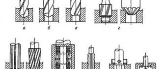
1. Right through cutter with a hard alloy plate 2. Groove cutter (high-speed steel R6M5) 3. External threaded cutter (high-speed steel R6M5) 4. Internal threaded cutter (high-speed steel R6M5) 5. Cut-off cutter (high-speed steel R6M5 or R6M5K5) 6 . Boring cutter (high-speed steel R6M5) 7. Pass-through cutter left (high-speed steel R6M5) 8. Scoring cutter (high-speed steel R6M5)
Cutter height, 8 mm or 10 mm
The price of one cutter is 499 rubles.
Hollow rotation hydraulic cylinders SMW AUTOBLOK
Application, benefits for buyers:
• drive for jaw and collet chucks with open center
• processing of shafts and pipes
Technical specifications
• pressure range 8–45 bar.
• short design/low weight/low energy consumption
• horizontal application only
• safety and overpressure relief valve
• fastening with bolts from the rear side
• a 10 micron filter is required in the high pressure line
• use HM32 ISO 3448 oil
Rotation hydraulic cylinder SMW AUTOBLOK 130/52 (rod diameter up to 52mm)
Rotation hydraulic cylinder SMW AUTOBLOK 150/67 VNK 152cm2SMW, designation 33094816 (analogue - hydraulic cylinder BISON 1305-150-67)
Application:
• drive for open-center jaw and collet chucks • machining of shafts and pipes
Accessories for jig boring machines
Jig boring machines are equipped with numerous devices, measuring and special cutting tools to perform high-precision work. These include a center finder with an indicator, an optical center finder, a center finder mandrel, an installation center, chucks, rotary dividing tables, etc.
Universal tool holder
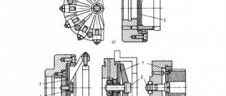
The universal tool holder (boring head) is designed for boring holes and trimming ends during spindle rotation and with automatic radial feed of the cutter.
The tool holder body is fixed in the machine spindle. The slide in which the cutter is secured can move in the housing along dovetail-type guides in the radial direction.
When trimming the end of the body, the tool holder rotates along with the machine spindle. The ring, connected to the ring by a handle, is kept from rotating. The ring contains pins, which, thanks to grooves and balls, can occupy two fixed positions: position E - on and position M - off. The sprocket, being in the tool holder body, rotates with it. When the machine spindle rotates, the sprocket, with its tooth, engages with the pin located in position E and rotates around its axis. The rotation angle of the sprocket axis per spindle revolution is determined by the number of engaged pins. The rotation of the sprocket is transmitted to a worm gear, the worm of which is made in one piece. The hub of the worm wheel is a nut into which a screw is screwed, which, when trimming the end of the part, is fixed in the slider. Consequently, when the worm wheel rotates, the slider will move radially along the stationary screw.
The pins are turned on (position E) and off (position M) when adjusting the tool holder manually, each pin separately, and to prevent the pin from falling out when turned on, there is a shoulder on the ring. There is an oiler at the end of the tool holder shank.
Centerfinder microscope
The microscope-centrefinder is designed to align the edge of the workpiece or any of its points with the axis of the spindle and to set the vertical plane of the workpiece parallel to the travel of the table or slide. The microscope body has a shank with which it is attached to the tapered hole of the machine spindle. The housing contains the optical part of the microscope, consisting of a lens, a prism (mirror), a grid with a crosshair and an eyepiece.
Scheme for aligning the position of the edge of the workpiece relative to the spindle axis. For this purpose, use a test square, which is placed on the workpiece and pressed by hand. The mark applied on the polished horizontal plane facing the microscope must coincide with the direction of the vertical plane of the square. The microscope is installed in the spindle of the machine. By observing the mark on the square through the eyepiece, one achieves an image in which the mark is located in the middle of the overlap. The vertical plane of the mark must coincide with the supporting surface of the square. A large set of various devices are attached to jig boring machines, such as a tool holder with precise feed, a universal tool holder, boring bars, etc.
Center finder with indicator
A center finder with an indicator is designed to align the holes of the workpiece fixed on the machine table with the spindle axis to align the perpendicularity of the end of the workpiece to the spindle axis to install a vertical plane or a generatrix of the cylindrical surface of the workpiece parallel to the table travel or slide.
The center finder body is fixed to a ruler, which is installed in the spindle with a conical shank. When testing internal cylindrical surfaces, the probe is pressed against the surface being tested by the force of the indicator spring through a lever. When checking external cylindrical surfaces, the handle with the rod must be pulled out from the center finder body and turned 90°. In this case, the spring will push the rod forward. The probe will be pressed against the controlled surface by spring force. When checking the ends, the probe is unscrewed and the indicator is secured with the measuring pin down. Alignment diagrams: shapes and locations of various surfaces: internal cylindrical, external cylindrical, horizontal and vertical.
As a rule, two dividing tables are attached to a jig boring machine. The dividing mechanism and faceplate design of both tables are the same, but differ in the presence of a device for tilting the faceplate.
Horizontal rotary index table
The table spindle can rotate with the faceplate about a vertical axis. Installation of parts on a rotary indexing table is used to work in rectangular and polar coordinate systems. The main purpose of horizontal rotary indexing tables is to accurately measure the angular values of rotation, which, while using a rectangular coordinate system, makes it possible to perform processing in a polar coordinate system, in which the coordinates are the distance between the axes of the holes and the angle measured from the measuring base. The rotary index table is fixed on the machine table after careful alignment of the relative position of the planes of the rotary index table faceplate and the table plane.
The position of the spindle rotation axis relative to the faceplate plane is checked with an indicator mounted in a special mandrel in the machine spindle. When processing parts with a rotating table, the axis of rotation of the spindle should be aligned with the axis of rotation of the indexing table. This alignment is carried out using an indicator center finder.
Machining of holes located along the radius of a circle in flat parts can be performed in both polar and rectangular coordinate systems.
Horizontal rotary index table can only rotate in a horizontal plane.
Universal rotary index table
The table has two dividing devices: the first one measures the angle of rotation of the faceplate plane around the vertical axis (0-360°), and the second one measures the angle of inclination from 0 to 90°. On universal rotary indexing tables, parts are marked and processed, the axes of the holes and planes of which are located at specified angles relative to their mounting and measuring bases. With one installation, the part can be bored and marked with holes specified in both rectangular and polar coordinate systems.
The angular values of the inclination of the spindle axis of a universal rotary table with a mechanical measuring system can be measured with an accuracy of 1-2, and with an optical measuring system with an accuracy of 1-6.
Universal rotary tables are installed on the machine table so that their mounting nuts fit into the exact T-shaped slots of the table. When installing a universal rotary table, check the parallelism of the working plane of the rotary table and the movement of the spindle or machine table, verticality when the axis of the faceplate and rotary table is horizontal, and the perpendicularity of the working plane of the faceplate to the axis of the machine spindle. These checks are carried out with an indicator installed in a special mandrel in the machine spindle.
Aligning the axis of the rotary table relative to the axis of the machine spindle using an indicator center finder and a centering rod with a ball tip.
Auxiliary tool
The auxiliary tool kit for jig boring machines can include nine interchangeable collets with diameters of 4, 5, 6, 8, 10, 12, 14, 16 and 18 mm for mounting tools with a cylindrical shank and a drill chuck for drills with a diameter of up to 10 mm. The machine can also be supplied with two sets of adapter bushings for fastening a tool with a tapered shank in the receiving cone of the Spindle, a spring core for marking on the machine and a cork table for fastening workpieces of small height or requiring fastening to a vertical plane. The box table is equipped with T-shaped slots on two strictly perpendicular planes.
Kinematics and characteristics of the machine
The focus of the production of machine tools is on quality, functionality and the requirement that the boring machine, in terms of the design of all its mechanisms, provides the necessary reliability and long service life.
The drawings of some horizontal boring machines resemble a tricky puzzle that can only be understood and configured by a team of qualified specialists from the manufacturer. Other machines have a passport, in which the kinematics of complex movements for the production of unique individual products of the most complex shape are indicated in the simplest way. All the kinematics here were put into a computer program, and the result was a CNC boring machine that was ineffective in terms of productivity, but necessary in terms of the “ability” to make complex products.
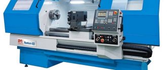
CNC Horizontal Boring Machine
Typically, the technical characteristics of the machine are contained in its passport, which indicates:
- dimensions (dimensions), weight of the machine;
- desktop area;
- description of the engine (usually engines);
- supply voltage;
- torques of all engines;
- spindle data;
- electrical circuit;
- kinematics;
- etc.
Kinematic diagram of horizontal boring machine 2L614
It is necessary to know kinematics when repairs of horizontal boring machines need to be carried out on their own. Typically, this work is performed by the manufacturer, who also trains the machine’s operating personnel. Due to the complexity of installation, configuration and maintenance, the modernization of horizontal boring machines is carried out by qualified specialists.
Typically, this procedure does not affect the kinematic diagram, but improves the technical characteristics of the machine model used, adapting it to the conveyor, production line or workshop for the production of a particular product.
The main characteristics of the kinematic diagram of almost any machine tool are equivalent: engine, gear system, couplings, gear shift unit. In this context, the horizontal boring machine, kinematic diagram, speed and dynamic characteristics of the engines, the main movements and functions of the table, spindle, faceplate are similar, and the differences lie in the range of speeds, diameter and size of the workpiece, direction and shape of movement at the point of contact of the workpiece and the cutting tool (cutter, drill, tap).
For each horizontal boring machine, the manufacturer includes the characteristics and principles of its operation in the passport and instructions for use. At the same time, the most important information for effective use is contained in the operating instructions.
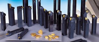
Main types of turning tools
A wide range of operations are performed on lathes. The most commonly used cutters are:
- Passage bent;
- Passing persistent
- cutting;
- boring;
- slotted;
- shaped;
- threaded
The specialist may require special-purpose tools.
Categories of cutters and types of surface treatment:
- The continuous thrust cutter is designed for processing, including end surfaces. To perform the operation of trimming a workpiece, you can use a bent cutter.
- Roughing cutters are used for preliminary turning and trimming of parts, during which the largest amount of material is removed. They also perform trimming of parts provided that most of the allowance is cut off. The geometric shape of the cutter allows you to achieve maximum equipment performance. The surface roughness parameters of the part do not require compliance at this stage of processing.
- A special grooving cutter or parting cutter is used to form an external or internal groove. If the width of the groove is less than its depth, then it is preferable to use turning in several axial cuts. If the workpiece being processed is thin-walled and not rigid, a smooth plunge at an angle is recommended.
- When boring various holes obtained through various technological operations with a rotating tool, boring cutters are used. Tools allow you to process holes, recesses, and other elements. The parameters of the cross-section and length of the cutting device must correspond to the dimensions of the processed part fragment.
- To cut threads efficiently, a turner needs appropriate thread cutters. The tool is selected based on the nuances of the design and material of the workpiece. In this case, the parameters of the profile, as well as the turning step, are taken into account. Technology and tools provide additional benefits.
Materials used for the manufacture of turning tools.
The materials used for the manufacture of the working part of the cutters must have the following basic properties:
- Hardness, which must be greater than the hardness of any metal processed by this cutter.
- Heat resistance, i.e. the ability to maintain the hardness inherent in a given cutter material when it is heated during the cutting process.
- Strength that provides the necessary resistance of the cutter head to destruction under chip pressure, and its cutting edge to chipping.
- Wear resistance from friction of chips on the front surface of the cutter and its rear surface on the cutting surface of the workpiece.
- Thermal conductivity is the ability to remove heat generated during the cutting process and entering the cutter from the place of its formation.
- Grindability, the ability to obtain (during sharpening or finishing) the required cleanliness of the surfaces of the cutter head, as well as sharp cutting edges.
Selecting a turning tool.
- Selection parameters. Part design and requirements for it. Part size, required shape, diameter difference, dimensional tolerances, surface roughness.
- Necessary operations. External or internal machining, roughing, semi-finishing, finishing, optimal number of passes, required number of settings, machining with axial tools.
- Part material. Hardness, delivery condition, rod, casting or forging, pre-machined or not, cooled machining or not.
- Economical processing. Reducing the processing cycle, increasing tool life, minimizing backlogs, costs per part, reducing downtime.
Recommended sequence for selecting a turning tool.
- Holder.
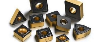
- Replacement plate
- Form
- Size
- Vertex radius
- Geometry
- Alloy
- Cutting modes