An ammeter is not such a rare device and they are often found in old chargers and other devices. But until you come across an ammeter, you won’t know that it turns out to need a shunt. Although, of course, there are ammeters with built-in shunts, but where there is direct current, the shunts are usually external. In chargers for car batteries, the shunts can be said to be homemade. There the shunt is a piece of metal wire with a diameter of about 2 mm.
When you remove the ammeter from the device, you can immediately remove the shunt, but if there is no shunt, you can make it yourself. I made shunts from copper wire, from a metal plate and wire, from a bolt with a diameter of 6mm, clamping the contacts with nuts and they all worked fine. Below is a diagram of connecting an ammeter with a homemade shunt made of copper wire.
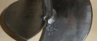
There is nothing complicated about making a shunt from copper wire. You need a piece of suitable wire with a cross-section of approximately 2.5 kV, this is for a 10-30A ammeter; if the current is higher, then a thicker cross-section is better. Next, the wire is stripped of insulation, and one wire from the ammeter is soldered to one end, and the second end must be moved along the wire until the ammeter readings coincide with the readings of the second connected ammeter. That is, to calibrate the readings you need a second working ammeter. This is what my homemade shunt looks like (below photo).
In general, there is nothing complicated about this, the fastest way is to make a shunt from copper wire, but you can, in principle, try and make a shunt similar to the factory one, although why would you do it if no one will see this shunt? The main thing is to correctly calibrate the homemade shunt, and for this you need a working second ammeter, or take a regular multimeter and turn it on to measure direct current.
Source: e-veterok.ru
Ammeter for a homemade power supply.
In order to make a shunt, it is necessary to calculate its resistance. Go to the “Site Map” page, select the “Programs” category, go to the “Programs” note and download the “Program for working with wire”. Yes, there is a program. Now we take the measuring head, it is better if it has a current of full deflection of the needle of 50 or 100 microamps. These parameters are called the sensitivity of the measuring head. Let's make a calculation for a head with a current of 50 microamps. Let's set the measured current, let's say 10A.
1) We measure the resistance of the device (head), for mine it is 1454 Ohms. 2) We substitute all available data into formula 1: Device current - Idevice = 0.00005A; The measured current is Imeasured = 10A. Device resistance Rdevice = 1454 Ohms. 3) The shunt resistance was determined Rsh=0.00727 Ohm.
Open the program. Press the second button at the top to determine the length of the shunt. On the right, from the drop-down list, select the material for the shunt. For such ammeters, I always use light tinned tin from condensed milk cans as a material. And so, we choose steel.
Its resistivity is approximately 10 times greater than that of copper, so the geometric dimensions of the shunt will be smaller. We measure the thickness of the tin with a micrometer; mine is 0.2 mm. We choose the width of the strip of tin, nine millimeters for a current of ten amperes, I think, is enough, especially since the flat conductor has a large cooling area.
If it gets very hot, then the width can be increased and the shunt can be recalculated. We determine the cross-sectional area of our shunt S=0.2×9=1.8 square mm. Select the input value - “cross-sectional area”. Enter this value in the appropriate window. Enter the value of the required shunt resistance. Click on “Result” and get the length of the conductor equal to 74 millimeters. Take jar 1 (Photo 1) and cut out the corresponding strip from its tin. In the photo I showed what shapes the shunt can be given. Number 4 is a shunt for printed wiring; the ends of the strip are soldered to the printed pads. In general, I always slightly increase the length of such shunts, which leads to an increase in their resistance and, as a consequence, an increase in the voltage drop across a given shunt at the same current. But it becomes possible to accurately adjust the ammeter readings using an additional resistor connected in series with the measuring head. See photo2.
Of course, you can also use a copper winding wire as a shunt resistor, but then the shunt will be very long. Let's try it though. We enter new data in the appropriate windows. Let's look at the next screenshot_2. We get a shunt in the form of a wire 51 cm long. Do not wind the wire into a coil and concentrate the heat in one place. Just thread this piece of wire through
Application
Thermometer -55…+150С with resolution 0.1С
As a sensor we use the LM35 sensor chip in the following configuration:
The approximate price of the chip is about 200 rubles ($6) for LM35CZ.
Schematic diagram of a thermometer
Operating temperature range, error and chip index
| marking* | temperature range | typical error at 25C** | TO-46 body | TO-92 body | SO-8 housing (SMD) | housing TO-220 |
| LM35 | -55…+155 | 0.4 | LM35H | |||
| LM35A | -55…+155 | 0.2 | LM35AH | |||
| LM35C | -40…+110 | 0.4 | LM35CH | LM35CZ | ||
| LM35CA | -40…+110 | 0.2 | LM35CAH | LM35CAZ | ||
| LM35D | 0…+100 | 0.4 | LM35DH | LM35DZ | LM35DM | LM35DT |
Note:
*A index means improved accuracy and linearity. **at the edges of the range the error is approximately 2 times higher, for more details see
I received from AliExpress a couple of electronic built-in voltmeters model V20D-2P-1.1 (DC voltage measurement), the price is 91 cents each. In principle, you can now find it cheaper (if you look hard enough), but it’s not a fact that this will not be to the detriment of the build quality of the device. Here are its characteristics:
- operating range 2.5 V - 30 V
- glow color red
- overall size 23 * 15 * 10 mm
- does not require additional power (two-wire version)
- there is a possibility of adjustment
- refresh rate: about 500ms/time
- Promised measurement accuracy: 1% (+/-1 digit)
And everything would be fine, put it in place and use it, but I came across information about the possibility of improving them - adding a current measurement function.
Digital Chinese voltmeter
I prepared everything I needed: a two-pole toggle switch, output resistors - one MLT-1 for 130 kOhm and a second wire resistor for 0.08 Ohm (made from a nichrome spiral with a diameter of 0.7 mm). And the whole evening, according to the found circuit and instructions for its implementation, I connected this equipment with wires to a voltmeter. To no avail. Either there was not enough insight in understanding what was left unsaid and incompletely drawn in the material found, or there were differences in the schemes. The voltmeter didn't work at all.
Connecting the digital voltmeter module
I had to unsolder the indicator and study the circuit. What was needed here was not a small soldering iron, but a tiny one, so it took quite a bit of fiddling. But over the next five minutes, when the entire scheme became available for review, I understood everything. In principle, I knew that this was where I needed to start, but I really wanted to solve the issue “easy.”
DIY ammeter shunt
Many home electricians are dissatisfied with industrial testers, so they think about how to make a voltmeter from an ammeter, as well as how to increase the functionality of the industrial tester.
For this purpose, a special shunt can be made. Before you begin, you should calculate the shunt for the microammeter and find a material with good conductivity.
Of course, for greater measurement accuracy, you can simply purchase a milliammeter, but such devices are quite expensive, and they are rarely used in practice.
Recently, testers designed for high voltage and resistance have appeared on sale. They do not require a shunt, but their cost is very high. For those who use a classic tester made in Soviet times, or use a homemade one, a shunt is simply necessary.
Which digital voltmeters are the most reliable?
The electrical equipment market is crowded with manufacturers who provide a wide variety of choices. However, not every device brings positive emotions from use. With a large number of products, it is not always possible to find a reliable and inexpensive copy.
Tested and reliable voltmeters include:
- TK 1382. Inexpensive Chinese, the average price of which rarely rises above 300 rubles. Equipped with tuning resistors. Performs measurements in the ranges 0-100 Volts, 0-10 Amps.
- YB27VA. Almost a twin of the previous voltmeter, it differs in the marking of the wires and at a reduced price.
- BY42A. It is more expensive than previous models, but also has an increased upper measurement limit of 200 V.
These are the most popular representatives of this type of voltmeters, which can be freely purchased for conversion on the radio market or ordered via the Internet.
Disadvantages of an industrial ammeter
Selecting a current ammeter is not an easy task. Most devices are produced in the West, in China or in the CIS countries, and each country has its own individual requirements for them. Also, each country has its own permissible values of direct and alternating current, requirements for sockets. In this regard, when connecting a Western-made ammeter to domestic equipment, it may turn out that the device cannot correctly measure current, voltage and resistance.
On the one hand, such devices are very convenient. They are compact, equipped with a charger and easy to use. A classic dial ammeter does not take up much space and has a visually clear interface, but it is often not designed for the existing voltage resistance. As experienced electricians say, there are “not enough amperes” on the scale. Devices designed in this way necessarily require shunting. For example, there are situations when you need to measure a value up to 10a, but there is no number 10 on the instrument scale.
Here are the main disadvantages of a classic factory ammeter without a shunt :
- Large error in measurements;
- The range of measured values does not correspond to modern electrical appliances;
- Large calibration does not allow small quantities to be measured;
- When trying to measure a large resistance value, the device goes off scale.
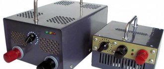
To charger
Those who like to design their own chargers will appreciate the ability to monitor the volts and amperes of the network, without the help of bulky portable devices. This will also appeal to those who work on expensive equipment, the operation of which can be adversely affected by regular drops in network voltage.
Using a Chinese ampere-voltmeter, which is no larger than a box of matches, you can easily monitor the state of the electrical network. One of the tangible problems that new electricians have may be the language barrier and wire markings that differ from the standard ones. Not everyone will immediately understand which wire needs to be connected where, and the instructions are usually only in Chinese.
100 V/10 A devices are very popular among independent designers. It is also desirable that the device have a shunt to finalize the connection process. A tangible advantage of this device is that it can be connected to a charger power source or to a separate battery.
*The power supply voltage of the ammeter and voltmeter must be in the range from 4.5 to 30 V.
The connection diagram is as follows:
- The black wire is negative. It also needs to be connected to minus.
- The red wire, which should be thicker than the black one, is a plus, and accordingly must be connected to the power source.
- The blue wire connects the load to the network.
If everything has been connected correctly, two scales should light up on the display.
Why is a shunt needed?
A shunt is necessary in order to correctly measure resistance in cases where the ammeter is not designed to measure such values. If a home craftsman often deals with such quantities, it makes sense to make a shunt for an ammeter with your own hands. Shunting significantly improves the accuracy and efficiency of its work. This is an important and necessary device for those who often use the tester. It is usually used by owners of the classic 91s16 ammeter. Here are the main advantages of a homemade shunt:
- Allows you to measure resistance where a factory or homemade ammeter does not have enough divisions on the scale;
- Helps adapt foreign ammeters to Russian electrical circuits;
- The accuracy of the tester is significantly increased;
- Protects the tester from damage and extends its service life. Any situation where the tester goes “off scale” is stressful for the device. If the ammeter goes “off scale” often (this usually happens if it is missing), the device quickly breaks down and is not easy to repair (it’s easier to buy a new one).
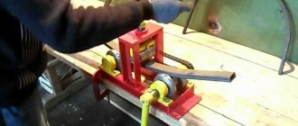
Manufacturing procedure
Even a freshman at a vocational school or a novice amateur electrician can easily handle making a shunt on his own. If connected properly, this device will greatly increase the accuracy of the ammeter and will last a long time. First of all, it is necessary to calculate the shunt for a DC ammeter. You can learn how to make calculations via the Internet or from specialized literature addressed to home electricians. You can calculate the shunt using a calculator.
To do this, you just need to substitute specific values into the finished formula. In order to use the calculation scheme, you need to know the real voltage and resistance for which a particular tester is designed, and also imagine the range to which you need to expand the capabilities of the tester (this depends on which devices a home electrician most often has to deal with ).
The following materials are perfect for manufacturing :
- Steel clip;
- Roll of copper wire;
- Manganin;
- Copper wire.
You can purchase materials in specialized stores or use what you have at home.
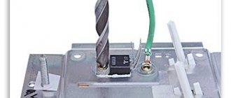
Essentially, a shunt is a source of additional resistance , equipped with four terminals and connected to the device. If steel or copper wire is used to make it, do not twist it into a spiral.
Useful tips
If a home electrician decides to purchase a commercially available ammeter, he should choose one with a fine calibration because it will be more accurate. Then, perhaps, you won’t need a homemade shunt.
When working with the tester, you should follow basic safety precautions. This will help prevent serious injury caused by electrical shock.
If the tester systematically goes off scale, you should not use it.
It is possible that the device is either faulty or is not able to show the correct measurement result without additional equipment. It is best to purchase modern domestically produced ammeters, because they are better suited for testing new generation electrical appliances. Before you start working with the tester, you should carefully read the operating instructions.
A shunt is a great way to optimize the home electrician's job of testing electrical circuits. In order to make this device with your own hands, you will only need a working industrial production tester, available materials and basic knowledge in the field of electrical engineering.
Source: obinstrumentah.info
V-meter modification scheme
Revision scheme: ammeter to voltmeter
This is how this scheme for connecting additional electronic components with those already existing in the voltmeter circuit was born. The standard resistor of the circuit marked in blue must be removed. I’ll say right away that I found differences from other circuits given on the Internet, for example, the connection of a tuning resistor. I didn’t redraw the entire voltmeter circuit (I’m not going to repeat it), I only drew the part that was necessary for modification. I think it’s obvious that the voltmeter’s power supply needs to be separate; after all, the starting point in the readings should start from zero. Later it turned out that power from a battery or accumulator will not work, because the current consumption of the voltmeter at a voltage of 5 volts is 30 mA.
Board - Chinese voltmeter module
After assembling the voltmeter, I got down to the essence of the action. I won’t split hairs, I’ll just show and tell you what to connect with what to make it work.
Shunt for an ammeter - how to make it yourself, calibrate and expand the capabilities of the tester
Measuring current is a fairly important procedure for calculating and testing electrical circuits. If you are creating a device with power consumption at the level of charging a mobile phone, a regular multimeter is enough to measure.
A typical inexpensive household tester has a current measurement limit of 10 A.
Most of these devices have an additional connector for measuring larger quantities. When rearranging the measuring cable, you probably haven’t thought about why you need to organize an additional circuit, and why you can’t just use the mode switch?
Why can’t one device measure a wide range of quantities?
The operating principle of any ammeter (pointer or coil) is based on converting the measured value into its visual display. Pointer systems operate on a mechanical principle.
A current of a certain magnitude flows through the winding, causing it to deflect in the field of a permanent magnet. There is an arrow attached to the reel. The rest is a matter of technique. Scale, markings, etc.
The dependence of the deflection angle on the current strength on the coil is not always linear; this is often compensated by a specially shaped spring.
To ensure measurement accuracy, the scale is made with as many intermediate divisions as possible. In this case, to ensure a wide measurement range, the scale must be of enormous size.
Or you need to have several instruments in your arsenal: an ammeter for tens and hundreds of amperes, a regular ammeter, a milliammeter.
In digital multimeters the picture is similar. The more accurate the scale, the lower the measurement limit. And vice versa - an overestimated value of the limit gives a large error.
A scale that is too busy is inconvenient to use. A large number of positions complicate the design of the device and increase the likelihood of loss of contact.
By applying Ohm's law to a section of the circuit, you can change the sensitivity of the device by installing a shunt for the ammeter.
Help: A shunt is a bypass resistance, a conductor connected parallel to the measured section of the circuit. Part of the current bypasses the main section, and less load falls on the connected device.
Let's start our study with theory:
Step-by-step instruction
So
,
step one
- an SMD resistor with a resistance of 130 kOhm is removed from the circuit, standing at the input of the positive power wire, between the diode and the trimming resistor 20 kOhm.
We connect the resistor to the voltmeter-ammeter
Second
.
On the free contact, on the side of the trimmer, a wire of the desired length is soldered (for testing, 150 mm is convenient and preferably red) Solder the SMD resistor
Third
. A second wire (for example, blue) is soldered to the track connecting the 12 kOhm resistor and the capacitor from the “ground” side.
How to calculate a shunt for an ammeter?
- Calculation of the shunt for a slight expansion of the upper limit of the ammeter scale. The shunt resistance is calculated using the formula. Rsh = (Ra * Ia)/(I - Ia) Rsh is the resistance that the shunt must have. Ra is the internal resistance of the ammeter without load. I is the expected current at which the instrument pointer takes the maximum position at the end of the scale. Ia is the current at which the instrument pointer takes the extreme position at the end of the scale without using a shunt. The resistance value is calculated by the formula in Ohms, the current in Amperes.
- Calculation of a shunt for an ammeter when the measurement limit is significantly exceeded. The shunt resistance is calculated using the formula. Rsh = (Ra * Ia)/I
How to choose a shunt for an ammeter as accurately as possible?
For the resistance selection stand we will need:
- power unit;
- exemplary device;
- high-quality wires (copper);
- variable resistance;
- the shunt itself and the ammeter for which it is being prepared.
The circuit is needed to accurately select the shunt resistance and calibrate the device with the installed pad.
Having set the minimum and maximum values under load (battery charge), we begin to stepwise change the current strength with variable resistance. The values obtained on the control device are plotted on the scale.
Let's remember physics. Video lesson on calculating a shunt for an ammeter.
Source: obinstrumente.ru