Pneumatic press for perforation and hot stamping
In this article I will describe the design and electrical circuit of a pneumatic press for hot stamping on leather and cardboard, which I assembled with my own hands. Such pneumatic presses can be called differently, depending on the scope of application.
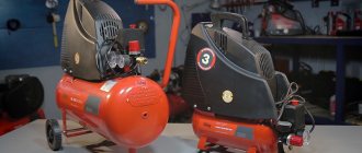
Unlike a hydraulic press, which is driven by a hydraulic pump, a pneumatic press develops pressure using compressed air produced by a compressor.
Based on the diagram and design described in the article, the following types of presses can work: perforation, hot stamping, various presses for molding and gluing parts.
Here, as an example, is my article about installing the Euroautomatika RT-820M temperature relay in a similar Turkish press.
In my case, the press is used in shoe production to hot-stamp the upper part of the shoe. As a result of the action of the press, a beautiful pattern or logo appears on the leather upper of shoes, shoes or boots. When installing a special mold and increasing the pressure, small holes can be drilled.
Agree, boots on a woman’s foot with a beautiful stylized flower on the top look much more impressive!
It is worth saying that a pneumatic press develops less pressure compared to a hydraulic one. But this is in the general case, it all depends on the specific model.
Pneumatic press operating algorithm
To understand the electrical circuit, consider the operating algorithm of a pneumatic press.
I’ll say right away that the photos were taken by me at the time of assembling the press. Before this, the press was assembled by a mechanic, but he couldn’t handle the electrical circuit, so I took over).
So, when the power is turned on, power is supplied to the heating elements, which heat the upper metal aluminum plate. It takes time to warm up the plate (about half an hour), and then the temperature is maintained by a thermal controller.
Time relay (top, set to 5 sec) and temperature controller.
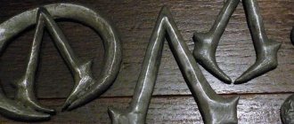
Front panel of a pneumatic press. The molds required for the production of this order are screwed to this plate.
The top plate into which two heating elements and a temperature sensor are inserted. Not screwed on. Must be screwed to the piston rod (four bolts at the top of the photo)
To start work, the operator presses two “Start” buttons. These buttons are connected electrically in series.
Why two, when one is enough? The fact is that this is necessary for safety reasons, so that at the moment the piston is lowered, both hands are on the buttons and do not accidentally fall under the press.
After pressing the “Start” buttons, the piston with the heated embossing mold is lowered, and the mold rests against the lower plate on which the workpiece lies.
In this case, a membrane-spring pneumatic actuator is used, but a conventional pneumatic cylinder can also be used.
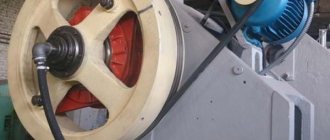
Pneumatic actuator based on membrane-spring pneumatic actuator
The same photo, from a different angle, is shown at the beginning of the article. Above is a tube where the compressed air supply hose is connected. Next, the air pressure can be adjusted using a reducer and monitored with a pressure gauge. Below is a solenoid coil and a valve that controls the air supply to the pneumatic drive (red container in the photo).
Next, the time is maintained, which is determined by the built-in timer (time relay). The timer delay time is set by the operator. This time depends on many factors (material, temperature, shape, design, etc.) and is usually selected experimentally.
After the delay time, the top plate rises, the cycle is completed.
Now you need to change the workpiece and repeat the cycle again.
Download documentation for the PVG-8-2-O press:
1. • Press PVG-8-2-0. Operating manual 24 sheets 48. Status: DEMO. Description: Press PVG-8-2-0. Manual. Introduction. Purpose of the press. Composition and technical characteristics. Device and principle of operation. Instructions for installation, start-up and operation. Security measures. Typical faults and methods for their elimination. Quality: 75%. File type: pdf. File size: 2.52 MB. Downloaded: 1318 times. Price – 600 rub. 2. • PVG-8-2-0. Original thyristor circuit + description of the circuit operation + description of the RPG module 3 sheets. Status: DEMO. Description: Original electronic quality. The diagram has been brought into a standard and more understandable form, errors have been corrected, many details, clarifications and additional information have been added. Quality: 100%. File type: pdf. File size: 954.14 kB. Downloaded: 504 times. Price – 300 rub. Two files for less! 600 + 300 = 800 rub.
3. • Press PVG-8-2-0. Diagram on contactors. Status: FREE. Description: Press PVG-8-2-0. Electrical circuit for starters (relays, contactors). Quality: 100%. File type: pdf. File size: 194.95 kB. Downloaded: 476 times.
4. • RPG module_full description_2page. Status: FREE. Description: Description of the RPG-01022204 module, which is the basis of the electronic circuit for controlling thyristors in the power control units of the presses PVG-8-2-0, PKP-10, PKP-16, PVG-18, etc. Quality : 100%. File type: pdf. File size: 378.44 kB. Downloaded: 900 times.
Diagram of a pneumatic hot stamping press
The diagram is simple, I drew it directly next to the press, I publish it as is:
Electrical circuit of a pneumatic hot stamping press.
The big disadvantage is that there is no electrical safety. It's not about grounding. This applies to the protective circuit breaker at the input (a maximum of 6A is enough here) and the “Emergency stop” button for emergency raising of the piston.
Anyone interested in circuit breakers - here, in emergency circuits - here.
The circuit consists of two independent parts - a heating element heating circuit and an air valve control circuit. Let's look at them.
Turning on heating elements via a thermal controller
To power the heating elements, a temperature controller (thermostat) BERME REX C100 FK-02 VAN SSR is used. The last three letters - SSR - indicate that the controller output is intended to control a solid state relay (Solid State Relay). Anyone who wants to know what it is and what its connection circuits are, I recommend my article about solid-state relays.
And who wants to buy such a Temperature regulator - the assembly kit is sold on Aliexpress!
Thermoregulator, also known as a temperature controller, also known as a temperature controller, also known as a temperature control relay and a temperature controller with an output for a solid-state relay.
What's great about this temperature controller? It is strikingly different from old, classic temperature controllers in that when approaching a set point, it turns off and catches up with the temperature in pulses with variable duty cycle. The closer the temperature is to the set value, the shorter the pulses. As a result, the temperature, depending on the settings, can be maintained with an accuracy of half a degree.
Smart thermal controller. I've seen these in places where special accuracy in setting the temperature is needed.
But the thermostats of the old system stupidly operate by hysteresis, as a result, depending on the design of the system and its inertia, the temperature varies within ±10...15 degrees.
The use of a “smart” temperature control relay would not be possible if a solid-state relay were not used as a switching element. A regular relay would have a hard time...
The feedback sensor gives feedback to the regulator, everything is clear here.
By the way, the accuracy of such a system greatly depends on the quality of the installation of heating elements and a temperature sensor. They must be installed so as to ensure reliable thermal contact with the heated plate, i.e. the contact must have minimal thermal resistance. In addition, it is important to install the sensor closer to the heating elements, especially if the mass of the heated metal is small and it cools intensively.
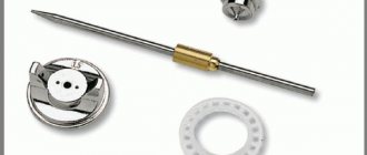
Temperature sensor and heating elements before installation in a metal plate
Solid State Relay – Fotek SSR-40 DA. DC voltage control 24V, switching – 220VAC.
Solid state relay – Fotek SSR-40 DA for turning on heating elements
Press pressure time delay
The delay during which the workpiece is “fried” is set using a TDM PB 2A time relay:
Time relay TDM PB2A for delay time adjustment
The time relay is a classic one, produced by many companies, from OMRON to China Noname. There may be different operating modes that are switched. From the diagram shown on the relay body, it is clear that it has two switching contacts. Moreover, one is with a shutdown delay, the second is normal.
Regarding time relays, their operating principles and circuit design, I recommend my major work. There, using the example of PVL, all theory and practice are considered.
I didn’t understand before why this relay needed a regular contact. Then it dawned on me - after all, it is needed for self-retaining, in order to fix it in the on state, like in a regular relay or contactor. This is described in detail in the article about magnetic contactor connection diagrams.
Let's look at the diagram. When the Start 1 and Start 2 buttons are pressed, the voltage through the NC contact PB1 is supplied to power the time relay PB, which turns on, and as a result its NO contacts PB2 are closed.
Contact PB1 is not simple, but with a switching delay. In this case, this means that it opens after a delay determined by the PB timer. And during this time, voltage is applied to the air valve.
That's all for the electrical circuit. Appearance during installation:
DIY installation of a pneumatic press circuit
Do-it-yourself hydraulic press from MAZ spare parts - DRIVE2
At first I made a version like everyone else - based on a hydraulic jack - the collective farm is poor, and besides, the Chinese jack leaked the first time it was used.
I was interested in the idea of remaking the press like here www.fermer.ru/forum/rtm-r…tornaya-masterskaya/95993
There, a man built a press from spare parts from a MAZ truck. The advantages of this approach:
- the MAZ cabin pump is used as a pump - the maximum operating pressure is 25 MPa, there is a safety valve that can be adjusted - shut off or set to a lower pressure. The pump has a reversible inlet and outlet, which allows the installation to change the direction of oil supply, so that in the working cylinder it is possible not only to lower the rod, but also to raise it!
- Maximum pressure developed by the pump, MPa: 25 Plunger diameter, mm: 16 Working volume, cm3: 8 Filling volume, cm3: 300 Actuation pressure of the safety valve in the filler plug, MPa: 2 Force on the handle at a distance of 600 mm from the longitudinal axis of the drive shaft, no more than, N : 350
- Weight, kg: 4.6
— The power cylinder power steering Maz TsG 80-280 is used as a working cylinder - a good product with thick walls, real metal, unlike a Chinese jack.
It is designed for a nominal pressure of 10 MPa, but can also withstand long-term overloads (naturally, since it is installed in the steering wheel of a heavy truck).
There is a thread at the end of the rod; adapters can be machined for different needs - metal bending, pressing, drawing, etc. Double acting cylinder.
- Working pressure, no more, MPa: 10 Working diameter of the cylinder, mm: 80 Rod diameter, mm: 28 Full stroke of the rod, mm: 280
- Weight, no more, kg: 13.5
— the connection is made with original MAZ copper tubes — for flaring you can buy a kit, which is also used for flaring car brake pipes. Although initially the tubes on sale are flared.
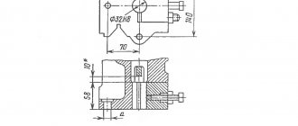
— It was necessary to machine an adapter to connect the pump to the power steering cylinder, because initially on MAZ it was connected to the cab lift cylinder, which is smaller and has a piston diameter of only 40 mm, not 80, and is not suitable for the needs of the press. Although it will be suitable for something else! I have attached a drawing of the fitting.
What pressure can such a device produce?
F = P*S = P*(pi*r^2)= 25,000,000 * (0.04 * 0.04 * 3.14) = 125600 Newtons, that is, the maximum force will be 12.5 tons of force
But this is an honest 12.5 tons of force, and not the Chinese 25, 30, etc. By the way, I initially wanted to buy a press, but I looked at all this shit that is sold for crazy money (from 15 to 40 thousand rubles.
) and changed his mind - it was made poorly, for example, the matrix press is based on a jack - even the jack handle is not cut off, others are made not from a channel, but from thin sheet metal, this does not increase strength, but reduces weight, which is important when delivering goods - according to Essentially logistics.
In general, this is a dangerous tool for health. If this crap flies in front of your face, it won't seem like much.
I used channel 14 and 16 as metal - a real hot roller channel, not a bent one. I welded it wherever possible, the braces on the upper platform were additionally welded and also secured with German high-strength bolts with index 12.0.
In order for the lower platform to be able to move the channel, it was given for milling - because 22 mm fingers connecting the tracks on tractors are used as locking pins. These fingers are made of a special alloy that will not let you down either.
Addendum 1. Another diagram of a pneumatic press
To complete the picture, I present a diagram that I created when restoring a press for gluing shoe parts. The operating algorithm is absolutely the same, the design is completely different.
Scheme of a rotary press for duplicating the toe cap of shoes
The materials used are coated with hot-melt adhesive. When pressed, the glue melts and the parts stick together.
The diagram is drawn clumsily, but that’s not the worst thing. The fact is that, instead of using the usual contacts of the time relay RL2, I additionally used the usual relay RL1. Although, in justification, I can say that the pneumatic valve is powered through a conventional relay (RL1.2), which is several times cheaper and more accessible. Which is more far-sighted and can be applied in the first scheme. By the way, after me this machine has been making shoes all over the country for more than 3 years.
Appendix 2. Application in a bookbinding workshop
A reader of mine sent me a photo of what a similar press can do in a bookbinding shop where beautiful books are made to order.
The press is used (to be honest, these are currently plans) to obtain high-quality blind embossing. This is when foil (of some color, many colors) is not placed under the cliche, and leather or leatherette is simply embossed with a hot cliche through a heat-resistant transparent film. The same leather (leatherette) darkens and becomes so-called. blind embossing. Foil stamping is also done.
Photo album, top cover and spine
My mother worked in a bookbinding shop, so I have an idea). True, a hand press was used there, and this is very labor-intensive.
That's all for today, I'm waiting for questions and constructive criticism in the comments.