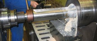
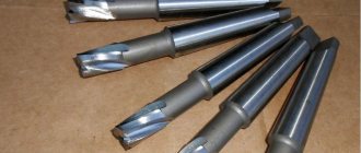
A centering drill is a special metal-cutting tool with a double-sided cutting part and, as a rule, a large diameter shank for clamping into a chuck. The drill has a main thin cutting part, as well as conical cutting edges for countersinking holes for drills of large diameters. Of all types of drills, it is the centering drill GOST 14952-75 that provides maximum quality and accuracy of drilling and strict perpendicularity, eliminating sliding on the surface, which is typical of conventional drills.
TEST METHODS
4.1. Testing of drills should be carried out on drilling, centering and turning machines using auxiliary tools, which must meet the standards of accuracy and rigidity established for them.
4.2. Drills should be tested on samples made of steel grade 45 according to GOST 1050-88 with a hardness of 187 - 207 HB.
(Changed edition, Rev. No.).
4.3. Durability tests are carried out on drills of type B, as well as type A, R or C with diameters of 0.5; 1.6; 2.0; 2.5; 4.0; 10.0 mm at the modes indicated in the table. 8.
4.3.1. Acceptance values of mean time to failure and 95% failure-free operating time should not be less than those indicated in table. 9.
(Changed edition, Rev. No.).
4.4. After performance tests, there should be no chipping on the cutting edges of the drills, and the drills should be suitable for further work.
4.5. A 5% (by weight) solution of emulsol in water with a flow rate of at least 5 l/min is used as a cutting fluid.
Table 8
| Diameter of the drill bit, mm | Feed, mm/rev, for types | Drilling depth, mm, for types | Cutting speed, m/min | Number of holes machined during performance tests | ||
| A, B, C | R | A, C, R | IN | |||
| 0,50 | 0,01 | 0,02 | 1,3 | — | 8 … 10 | 13 |
| 0,63 | 1,5 | — | ||||
| 0,80 | 1,9 | 2,1 | ||||
| 1,00 | 2,3 | 2,6 | ||||
| 1,40 | 0,02 | 2,8 | 3,2 | 25 | ||
| 1,60 | 3,5 | 4,0 | ||||
| 2,00 | 0,04 | 4,4 | 5,0 | |||
| 2,50 | 0,07 | 5,5 | 6,3 | 11 … 13 | 30 | |
| 3,15 | 7,0 | 8,0 | ||||
| 4,00 | 0,08 | 8,9 | 10,1 | 24 | ||
| 5,00 | 0,10 | 11,2 | 12,7 | 14 | ||
| 6,30 | 0,12 | 14,0 | 15,4 | 18 | ||
| 8,00 | 17,9 | 19,5 | 15 | |||
| 10,00 | 22,5 | 24,5 | ||||
Table 9
| Diameter of the drill bit, mm | Acceptance values of operating time for drill type | |||
| A, R, C | IN | |||
| average | 95% | average | 95% | |
| 0,5, 0,63, 0,8, 1,0 | 150 | 45 | 105 | 32 |
| 1,25, 1,6 | 190 | 56 | 140 | 42 |
| 2,0 | 270 | 77 | 170 | 50 |
| 2,5, 3,15 | 290 | 88 | 190 | 56 |
| 4,0, 5,0 | 175 | 53 | 120 | 35 |
| 6,3, 8,0, 10,0 | 150 | 45 | 95 | 28 |
(Changed edition, Rev. No.).
4.6. The hardness of drills is measured according to GOST 9013-59.
4.7. Appearance control is carried out visually.
4.8. The surface roughness parameters of drills should be checked by comparison with roughness samples in accordance with GOST 9378-75 or with standard tools, the values of the surface roughness parameters of which are not more than those specified in clause 2.3.
Comparison is carried out visually using a magnifying glass LP-2 - 4´ according to GOST 25706-83.
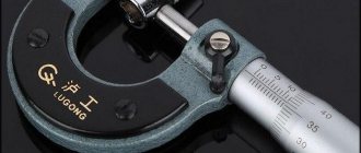
4.9. When monitoring drill parameters, control methods and means must be used, the error of which should not be more than:
when measuring linear dimensions - the values specified in GOST 8.051-81;
when measuring angles - 35% of the tolerance value for the angle being tested;
when monitoring the shape and location of surfaces - 25% of the tolerance value for the parameter being tested.
Sec. 4. (Changed edition, Amendment No. 2).
TECHNICAL REQUIREMENTS
2.1. Drills must be made of high-speed steel - in accordance with GOST 19265-73.
2.2. The hardness of the working part of centering drills should be: for drills with a diameter of up to 3.15 mm - 63...65 HRC; for drills with a diameter over 3.15 mm - 63...66 HRC. The hardness of the working part of drills made of high-speed steel with a vanadium content of 3% or more and cobalt of 5% or more should be higher by 1-2 HRC units.
2.3. The roughness parameters of drill surfaces according to GOST 2789-73 should not exceed the values specified in Table 5.
Table 5
µm
| Names of surfaces | Roughness parameters according to GOST 2789-73 | |||
| Version 1 | Version 2 | |||
| The rake surface of the drilling part and the surface of the flutes | — | 6,3 | — | 10,0 |
| Rear surface of drilling and countersinking part | — | 3,2 | — | 6,3 |
| Surface of the clamping cylindrical part | 0,63 | — | 1,25 | — |
2.2, 2.3. (Changed edition, Amendment No. 2).
2.4. Cracks, nicks, rough spots and tarnished colors are not allowed on the surfaces of centering drills (with the exception of grooves, where tarnished colors are allowed at the point where the wheel exits).
2.5. Maximum deviations in the dimensions of combined drills should not exceed: the diameter of the drill part. . . k12; diameter of the clamping cylindrical part. . . h9; cone angles 60° and 75°. . . minus 30′; cone angle 120°. . . ±1°. Note. The dimensions of the nominal diameters of the drilling part should be measured at the beginning of the cutting part. (Changed edition, Amendment No. 3).
2.6. Drills of types A, B and C must have a reduction in diameter on the drilling part towards the shank (reverse taper) within 0.05-0.10 mm per 10 mm of length. (Changed edition, Amendment No. 2).
2.7. The thickening of the core of combination drills towards the shank by 5 mm in length should be:
| for drills up to 3.15 mm diameter | 0.40 mm | ||
| » » St. 3.15 mm | 0.25 mm | ||
2.8. The tolerance for radial runout of the auxiliary edges of the drilling part relative to the axis of the clamping part should be no more than:
| for drills up to 3.15 mm diameter | 0.03 mm | ||
| » » St. 3.15 mm | 0.04 mm | ||
2.9. The axial runout tolerance, checked at the center of the cutting edges, should be no more than:
| for drills up to 6.0 mm diameter | 0.10 mm | ||
| » » St. 6.0 mm to 10.0 mm | 0.13 mm | ||
| » » St. 10.0 mm | 0.15 mm | ||
For drills with a diameter of up to 6 mm, instead of the tolerance of the end runout of the drilling part, it is allowed to check: the difference in half the angle at the tip of the drill, which should not be more than 1°30′; symmetry tolerance in radius expression of the transverse edge relative to the axis of the clamping part of the drill:
| for drills up to 3.15 mm diameter | 0.05 mm | ||
| » » St. 3.15 mm | 0.10 mm | ||
(Changed edition, Amendment No. 2).
2.10. The difference in the widths of the feathers on one drill should be no more than:
| for drills up to 3.15 mm diameter | 0.07 mm | ||
| » » St. 3.15 mm | 0.10 mm | ||
2.11. The values of average time to failure and 95% failure-free operating time of drills made of R6M5 steel, version 2, under the test conditions specified in Section 4, must be no less than those given in Table 6.
Table 6
| Diameter of the drill bit, mm | Operating time (number of holes machined) with drill type | |||
| A, R, C | IN | |||
| average | 95% | average | 95% | |
| 0,5, 0,63, 0,8, 1,0 | 130 | 39 | 90 | 27 |
| 1,25, 1,6 | 160 | 48 | 120 | 36 |
| 2,0 | 220 | 66 | 145 | 43 |
| 2,5, 3,15 | 250 | 75 | 160 | 48 |
| 4,0, 5,0 | 150 | 45 | 100 | 30 |
| 6,3, 8,0, 10,0 | 130 | 39 | 80 | 24 |
Note. For drills of version 1, the correction factor for the average and specified service life is 1.3. (Changed edition, Amendment No. 3).
2.12. The criterion for failure of centering drills with a diameter of up to 3.15 mm is breakage, and from 4 mm and above - wear on the rear surface in accordance with Table 7.
Table 7
mm
| Drill bit diameter | |
| 4,0, 5,0 | 0,4 |
| 6,3, 8,0, 10,0 | 0,5 |
2.11, 2.12. (Introduced additionally, Amendment No. 2).
2.13. On each drill the following must be clearly marked: the diameter of the drill part; manufacturer's trademark; drill designation (last four digits); steel grade. Notes:
1. On drills with a diameter of less than 10 mm, it is allowed not to mark the drill designation.
2. Steel grades R6M5 are allowed; R6AM5 should not be marked.
3. It is allowed to mark the letters HSS instead of the high-speed steel grade; for steel grades containing cobalt, the letters HSS C, while the grade is now indicated only on labels.
2.14. Packaging, marking of transport and consumer containers - in accordance with GOST 18088-83.
2.13, 2.14. (Introduced additionally, Amendment No. 3).
Use in home workshops
At home, combination centering drills are used primarily for making small holes and unscrewing stuck hardware. In home workshops, designs with a diameter of 0.8 mm are used.
Before using this tool, you need to perform its initial sharpening:
- Buy a tool for sharpening drills. Very often, electric machines with holes for drills are used to sharpen metal-cutting structures.
- Determine drill size. To do this, it is necessary to analyze the size tables, which indicate the diameter for any type of centering drill.
- Place the product in a special hole in the electric machine. The sharpening process is performed automatically, without human control.
- Pull the tool out of the machine hole and clean it from unnecessary chips and other types of contaminants.
If the geometry of the tool is disrupted during the sharpening process, the drill’s cutting speed and accuracy criteria will decrease. This will lead to excessive heat generation and rapid wear of the product.
The working area is placed on the made recess. The procedure for making a hole must be done with a light feed and without unnecessary pressure. After completing the procedure, the instrument is cleaned of dirt. For further use of the centering drill, it must be stored in closed containers (boxes or cases).
If you find an error, please select a piece of text and press Ctrl+Enter.
Design Features
Outwardly, this tool does not look like a drill in the classical sense of the word. The main feature of the design is the thickened base, which is 2-3 times larger in diameter relative to the main working part. Also, this tool is not longer than other types of similar equipment. This resulted in a drill with a reinforced base, which gives it increased rigidity. During operation, it does not vibrate or bend, which allows you to perform high-precision work.
The center drill consists of three parts:
- central part, a working area of smaller diameter, which easily drills metal,
- main part, second working area, larger in diameter, increasing the diameter of the hole,
- base, area for fixing the tool in the equipment.
How this drill can be used in construction and repair
This tool is classified as professional. However, craftsmen have learned to use it in construction, using it as a countersink for metal or wood. In the latter version, it is also convenient in that it can simultaneously make a guide hole for a self-tapping screw and groove a countersunk hole for its head, or for installing fittings where it is necessary to center the hole.
It can also very effectively drill out the head of self-tapping screws and screws that do not want to come out.
This tool is often used by radio amateurs to make holes in circuit boards. They use a small drill diameter: 0.5-1.5 mm; in these cases, conventional drills often break, and the centering drill lasts much longer due to its design.
Use at home
Despite the fact that centering drills are professional, many home craftsmen have found successful use for them. Such drills are very popular among radio amateurs, who often have to drill small-diameter holes in printed circuit boards. Possessing high rigidity due to the features of their design, centering type drills in such situations are more preferable than a standard small-diameter drilling tool.
Drilling holes in a printed circuit board
One of the operations that can be successfully performed using a centering tool is drilling out screws or screws that cannot be removed with a regular screwdriver. Using a centering tool, the heads of such recalcitrant fasteners are simply drilled out, after which they can be easily unscrewed. The easiest way to solve this problem is to drill out the head of a screw or screw, which has slots for Phillips-type screwdrivers. If we are talking about a head with slots for a straight screwdriver, then it must first be marked to indicate the exact location of the drill.
Centering drill with screw sharpening and Morse taper shank
It will not be difficult for any home craftsman to purchase a centering tool of any diameter. Today there is a large assortment of drills available for free sale, including both domestic and foreign brands.
If we talk about the preferences of home craftsmen, then, judging by reviews and recommendations, centering drills produced under the well-known Dormer brand are very popular among them. This tool is distinguished by high quality workmanship, as can be judged even from its photo; it is reliable and durable in use.
Dormer center drills are made from high speed tool steel HSS
The centering tool TM Dormer is made of high-speed steel and is subjected to special heat treatment to ensure high hardness of the finished product. As a result of such technological manipulations, a tool is obtained that can easily drill very hard metals, including stainless steel.
The manufacturer adds cobalt to the metal from which Dormer centering drills are made, which allows the cutting tool to maintain its original hardness even at elevated processing temperatures. The wear resistance of the products of this brand also deserves praise.
Domestic use
Despite the fact that center tools are considered professional, many home craftsmen successfully use them. Such devices are common among radio amateurs, who often drill small holes in printed circuit boards. Having increased rigidity, centering tools are excellent for such work.
In domestic conditions, devices are mainly used whose diameter is 0.05-0.08 cm. This is due to the fact that a small cutting element makes it possible to solve many household problems with great efficiency.
One of the procedures that is carried out using a centering drill is the drilling of screw and screw elements. Often it is impossible to unscrew them with an ordinary screwdriver. Using a drill, the heads of the screws/screws are drilled out and then easily unscrewed. Drilling is especially easy if the fastener parts have slots for Phillips screwdrivers. If the slots are intended for straight screwdrivers, you need to tilt the head to mark the entry area of the drilling tool.
Every home craftsman can easily buy a center drill of any size. Currently, stores offer many varieties of drilling tools, both Russian and imported.
If you read reviews from home craftsmen, it becomes obvious that the most common products are from. These drills are high quality, reliable, and have a long service life.
Dormer center drills are made from high-speed metal. In addition, they undergo special heat treatment to ensure maximum hardness of the device. After passing all the technological procedures, a product is created that can easily drill through hard materials, for example, stainless steel.
The manufacturer adds cobalt to the steel from which Dormer center tools are made. This allows the cutting element to remain hard even in high temperature conditions. The wear resistance of Dormer products is very high. It is not for nothing that drills of this brand are given such a long warranty.
A significant characteristic of Dormer tools is that they are self-centering. Thanks to this, it is possible to create holes with high location accuracy. Like other manufacturers, it produces centering devices of various sizes.
Application
The centering drill is used for drilling both metal and wooden surfaces. However, “according to the passport”, that is, for its intended purpose, this tool should be used only for processing steel materials. However, this did not stop our builders from using it as a countersink for wood, for example, when it is necessary to deepen a hole for the incoming screw head. Thanks to their heat-resistant and high-strength construction, they absolutely do not fail after processing similar objects and materials.
As for their intended purpose, these tools are widely used for drilling holes on milling, drilling and turning machines. In addition, centering drills can also be used at home. Radio amateurs also like to use such devices. Such drills are more necessary than ever for making holes in printed circuit boards. And since the devices used are highly rigid (this is determined not only by their composition, but also by the special geometry, which we talked about a little earlier), it is very easy and convenient to work with them.
Purpose of centering drills
This type of drill (which, however, is almost not similar to ordinary drills) is intended for making centering holes in various hard materials: metals, metal-ceramic alloys, hard wood, as well as for countersinking or drilling out fasteners. Centering drills are most often used for centering workpieces or parts on lathes, as well as preliminary precise drilling of parts before their further processing on a drilling or milling machine. At the same time, no other professional tool can provide such accuracy of holes (located perpendicular to the surface of the product to be processed) as self-centering drills.
APPENDIX 1 (recommended)
APPENDIX 1 Recommended
The design, dimensions and geometric parameters of the drills are indicated in Figures 1-4 and Tables 1-4.
Damn.1. Type A
Type A
Form 1. Oblique flute drill
For diameters up to 0.8 mm
For diameters St. 0.8 mm
Form 2. Drills with helical flute
Damn.1
Note. The 100° angle and radius are given in a section perpendicular to the slope of the groove.
Table 1
Dimensions in mm
| (0,50) | 5 | 0,10 | 0,03 | 0,10 | — |
| (0,63) | 6 | 0,10 | 0,04 | 0,24 | |
| (0,80) | 7 | 0,15 | 0,05 | ||
| 1,00 | 8 | 0,20 | 0,06 | 0,30 | 15° |
| (1,25) | 9 | 0,25 | 0,07 | ||
| 1,60 | 11 | 0,30 | 0,10 | ||
| 2,00 | 12 | 0,40 | 12° | ||
| 2,50 | 15 | 0,45 | 0,16 | 0,50 | |
| 3,15 | 17 | 0,55 | |||
| 4,00 | 20 | 0,70 | 0,25 | 0,80 | |
| 5,00 | 24 | 0,85 | |||
| 6,30 | 27 | 1,10 | 0,40 | ||
| 8,00 | 34 | 1,40 | 1,00 | ||
| 10,00 | 38 | 1,70 | 0,60 |
Damn.2. Type B
Type B Form 1. Oblique flute drills
Form 2. Drills with helical flute
Damn.2
Note. The 100° angle and radius are given in a section perpendicular to the slope of the groove.
table 2
Dimensions in mm
| (0,80) | 9 | 0,15 | 0,05 | 0,2 | — |
| 1,00 | 10 | 0,20 | 0,06 | 0,3 | 28° |
| (1,25) | 11 | 0,25 | 0,07 | 26° | |
| 1,60 | 13 | 0,30 | 0,10 | 24° | |
| 2,00 | 16 | 0,40 | |||
| 2,50 | 19 | 0,45 | 0,16 | 0,5 | |
| 3,15 | 21 | 0,55 | 21° | ||
| 4,00 | 24 | 0,70 | 0,25 | 0,8 | 19° |
| 5,00 | 27 | 0,85 | |||
| 6,30 | 31 | 1,10 | 0,40 | ||
| 8,00 | 35 | 1,25 | 1,0 | ||
| 10,00 | 39 | 1,40 | 0,60 |
Damn.3. Type C
Type C For diameter =0.8 mm
For diameter St. 0.8 mm
Damn.3
Table 3
mm
| 0,8 | 8 | 0,15 | 0,05 | 0,2 |
| 1,0 | 0,20 | 0,06 | 0,3 | |
| 1,6 | 11 | 0,30 | 0,08 | |
| 2,0 | 14 | 0,40 | 0,10 | |
| 2,5 | 16 | 0,45 | 0,14 | 0,5 |
Using hob sharpening equipment
When processing workpieces, hobs are often used.
The characteristics of cutters are strictly prescribed by GOST 9324-60 and are produced:
- whole;
- prefabricated (welded, plug-in).
Prefabricated cutters (for modules from 10 to 16) are used with insert combs made of high-speed cast steel or forged.
Hobs (for modules 18 to 30) are manufactured by welding and mounting carbon steel teeth on a base.
When using hobs to cut cylindrical gears, the working parts of the tooth wear differently in different areas.
To increase the service life of hob cutters, you can use the height correction method by changing the shape of the spatial curve along which the working process occurs. The method of axial displacement of the tool is also used, which increases the speed of operations with an increase in the service life of the cutters.
The process of sharpening backed hob cutters is carried out along the front part, and sharpened ones are carried out along the back surface of the tooth. After the process is completed, measurements are taken:
- front surface profile;
- circumferential pitch;
- compliance of chip flutes.
Popular manufacturers
Foreign analogues are manufactured with markings that differ from domestic ones, according to current foreign standards. Their correspondences can be found on the Internet and in the accompanying documentation. Among manufacturers, centering tools from DeWALT (USA), Werko, Robert Bosch GmbH (Germany), YG-1 (South Korea) and some manufacturers from China are especially popular. In the latter case, it is necessary to study customer reviews so as not to buy goods from unscrupulous manufacturers.
The video describes in detail the purpose and design of centering drills:
How to sharpen such a drill
Since this tool is a professional one, it must be sharpened with strict adherence to all angles of the cutting parts so as not to disturb the geometry. This can lead to negative consequences:
- reducing cutting speed,
- decrease in accuracy,
- excessive heat generation during operation,
- reducing the length of the working part,
- rapid wear.
This operation is performed on special equipment by experienced sharpeners.
You can sharpen such a drill at home. For this, there are special devices with which you can set the correct angle. An experienced craftsman can easily do this work “by eye”; it is enough to ensure that the front (cutting) edge of the working part is higher than the back, if the drill is positioned strictly vertically. In its principle, the technology is no different from that used for sharpening conventional drills.
