In order to connect parts together using rivets, pins, bolts, studs and screws, holes are usually required. For through holes for fasteners , there is a standard that recommends using nominal size values.
GOST 11284 − 75
| Through holes for fasteners | |||
| d | d1 | ||
| 1st row | 2nd row | 3rd row | |
| 1,0 | 1,1 | 1,2 | 1,3 |
| 1,2 | 1,3 | 1,4 | 1,5 |
| 1,4 | 1,5 | 1,6 | 1,8 |
| 1,6 | 1,7 | 1,8 | 2,0 |
| 1,8 | 2,0 | 2,1 | 2,2 |
| 2,0 | 2,2 | 2,4 | 2,6 |
| 2,5 | 2,7 | 2,9 | 3,1 |
| 3,0 | 3,2 | 3,4 | 3,6 |
| 3,5 | 3,7 | 3,9 | 4,2 |
| 4,0 | 4,3 | 4,5 | 4,8 |
| 4,5 | 4,8 | 5,0 | 5,3 |
| 5,0 | 5,3 | 5,5 | 5,8 |
| 6,0 | 6,4 | 6,6 | 7,0 |
| 7,0 | 7,4 | 7,6 | 8,0 |
| 8,0 | 8,4 | 9,0 | 10,0 |
| 10,0 | 10,5 | 11,0 | 12,0 |
| 12,0 | 13,0 | 14,0 (13,5) | 15,0 (14,5) |
| 14,0 | 15,0 | 16,0 (15,5) | 17,0 (16,5) |
| 16,0 | 17,0 | 18,0 (17,5) | 19,0 (18,5) |
| 18,0 | 19,0 | 20,0 | 21,0 |
| 20,0 | 21,0 | 22,0 | 24,0 |
| 22,0 | 23,0 | 24,0 | 26,0 |
| 24,0 | 25,0 | 26,0 | 28,0 |
| 27,0 | 28,0 | 30,0 | 32,0 |
| 30,0 | 31,0 | 33,0 | 35,0 |
| 33,0 | 34,0 | 36,0 | 38,0 |
| 36,0 | 37,0 | 39,0 | 42,0 |
| 39,0 | 40,0 | 42,0 | 45,0 |
| 42,0 | 43,0 | 45,0 | 48,0 |
| 45,0 | 46,0 | 48,0 | 52,0 |
| 48,0 | 50,0 | 52,0 | 56,0 |
| 52,0 | 54,0 | 56,0 | 62,0 |
| 56 | 58 | 62 | 66 |
| 60 | 62 | 66 | 70 |
| 64 | 66 | 70 | 74 |
| 68 | 70 | 74 | 78 |
| 72 | 74 | 78 | 82 |
| 76 | 78 | 82 | 86 |
| 80 | 82 | 86 | 91 |
| 85 | 87 | 91 | 96 |
| 90 | 93 | 96 | 101 |
| 95 | 98 | 101 | 107 |
| 100 | 104 | 107 | 112 |
| 105 | 109 | 112 | 117 |
| 110 | 114 | 117 | 122 |
| 115 | 119 | 122 | 127 |
| 120 | 124 | 127 | 132 |
| 125 | 129 | 132 | 137 |
| 130 | 134 | 137 | 144 |
| 140 | 144 | 147 | 155 |
| 150 | 155 | 158 | 165 |
| 160 | 165 | 168 | 175 |
Part connections
All connections of various parts that are used in mechanical engineering and instrument making are divided into movable and fixed. In this case, those that ensure the movement of parts relative to each other are considered movable, and those that require rigid fastening between them are considered stationary.
The possibility of repeated assembly and disassembly of components and assemblies of machines and equipment is ensured by detachable connections. These include threaded, splined, keyed, profile, pin and terminal.
Unlike detachable ones, permanent connections cannot be disassembled without damaging the parts. These include welded, adhesive, soldered, riveted joints, as well as joints with guaranteed interference. In technology, connections play an extremely important role, and many malfunctions in the operation of machines and equipment, as well as accidents, often occur because their parts were poorly connected to each other.
GOST 11284-75 Through holes for fasteners. Dimensions
INTERSTATE STANDARD
| THROUGH HOLES FOR FASTENING PARTS | GOST 11284-75 Instead of GOST 11284-65 |
| Dimensions | |
| Through holes for fasteners. Dimensions |
Resolution of the State Committee of Standards of the Council of Ministers of the USSR dated November 14, 1975 No. 3134 established the date of introduction
01.01.77
Edition 2006 with Change No. 1, approved in December 1981 (IUS 2-82).
The validity period was lifted according to Protocol No. 7-95 of the Interstate Council for Standardization, Metrology and Certification (IUS 11-95)
1. This standard establishes the dimensions of through holes for bolts, screws, studs and rivets with rod diameters from 1.0 to 160 mm, used to connect parts with gaps.
2. The dimensions of through holes must correspond to those indicated in the drawing and table.
mm
| Fastener rod diameter d | Through hole diameter dh | ||
| 1st row | 2nd row | 3rd row | |
| 1,0 | 1,1 | 1,2 | 1,3 |
| 1,2 | 1,3 | 1,4 | 1,5 |
| 1,4 | 1,5 | 1,6 | 1,8 |
| 1,6 | 1,7 | 1,8 | 2,0 |
| 1,8 | 2,0 | 2,1 | 2,2 |
| 2,0 | 2,2 | 2,4 | 2,6 |
| 2,5 | 2,7 | 2,9 | 3,1 |
| 3,0 | 3,2 | 3,4 | 3,6 |
| 3,5 | 3,7 | 3,9 | 4,2 |
| 4,0 | 4,3 | 4,5 | 4,8 |
| 4,5 | 4,8 | 5,0 | 5,3 |
| 5,0 | 5,3 | 5,5 | 5,8 |
| 6,0 | 6,4 | 6,6 | 7,0 |
| 7,0 | 7,4 | 7,6 | 8,0 |
| 8,0 | 8,4 | 9,0 | 10,0 |
| 10,0 | 10,5 | 11,0 | 12,0 |
| 12,0 | 13,0 | 14,0(13,5) | 15,0(14,5) |
| 14,0 | 15,0 | 16,0(15,5) | 17,0(16,5) |
| 16,0 | 17,0 | 18,0(17,5) | 19,0(18,5) |
| 18,0 | 19,0 | 20,0 | 21,0 |
| 20,0 | 21,0 | 22,0 | 24,0 |
| 22,0 | 23,0 | 24,0 | 26,0 |
| 24,0 | 25,0 | 26,0 | 28,0 |
| 27,0 | 28,0 | 30,0 | 32,0 |
| 30,0 | 31,0 | 33,0 | 35,0 |
| 33,0 | 34,0 | 36,0 | 38,0 |
| 36,0 | 37,0 | 39,0 | 42,0 |
| 39,0 | 40,0 | 42,0 | 45,0 |
| 42,0 | 43,0 | 45,0 | 48,0 |
| 45,0 | 46,0 | 48,0 | 52,0 |
| 48,0 | 50,0 | 52,0 | 56,0 |
| 52,0 | 54,0 | 56,0 | 62,0 |
| 56 | 58 | 62 | 66 |
| 60 | 62 | 66 | 70 |
| 64 | 66 | 70 | 74 |
| 68 | 70 | 74 | 78 |
| 72 | 74 | 78 | 82 |
| 76 | 78 | 82 | 86 |
| 80 | 82 | 86 | 91 |
| 85 | 87 | 91 | 96 |
| 90 | 93 | 96 | 101 |
| 95 | 98 | 101 | 107 |
| 100 | 104 | 107 | 112 |
| 105 | 109 | 112 | 117 |
| BY | 114 | 117 | 122 |
| 115 | 119 | 122 | 127 |
| 120 | 124 | 127 | 132 |
| 125 | 129 | 132 | 137 |
| 130 | 134 | 137 | 144 |
| 140 | 144 | 147 | 155 |
| 150 | 155 | 158 | 165 |
| 160 | 165 | 168 | 175 |
Notes:
1. The 3rd row of holes is not allowed to be used for rivet connections.
2. Recommendations for choosing rows of through holes are given in the appendix.
3. Dimensions in brackets are not recommended.
3. Limit deviations of hole diameters:
for the 1st row - H12;
for the 2nd row - H13;
for the 3rd row - H14.
1 — 3. (Amended edition, Rev. No. 1
).
4. If necessary, eliminate contact with the edge of the hole with a radius under the head of the fastener; It is recommended to countersink the hole.
(Introduced additionally, Rev. No. 1
).
APPLICATION
Recommended
RECOMMENDATIONS FOR SELECTING ROWS OF THROUGH HOLES
1. When independently processing the holes of each part of the connection with the distance between the axes of the most distant holes less than 500 mm, for connections for which only assembly requirements are imposed, it is recommended to select rows of through holes according to the table below.
Connection type
| Number and location of holes | Hole forming method | Connection type | Recommended number of through holes |
| Any number of holes and any location | Machining holes for jigs | I and II | 1st row |
| a - the holes are located in one row and coordinated relative to the hole axis or reference plane | Punching holes with high precision dies, injection molding and high precision lost wax casting | I | |
| II | 2nd row | ||
| b - holes (up to four in number) are located in two rows and coordinated relative to their axes | Processing holes according to markings, punching with stamps of normal accuracy, casting of normal accuracy | I | 2nd row |
| II | 3rd row | ||
| a - holes are located in two or more rows and coordinated relative to the axes of the holes or base planes b - holes are located around the circumference | Punching holes with high precision dies, injection molding and high precision lost wax casting | I and II | 2nd row |
| Processing holes according to markings, punching with stamps of normal accuracy, casting of normal accuracy | I | 3rd row |
2. For connections that are subject to assembly requirements and additional requirements to ensure a certain degree of relative movement of parts, as well as for connections that are subject to only assembly requirements, but with distances between the axes of the most distant holes in the parts of 500 mm or more, it is allowed to accept coarser ones (compared to recommended in the table) rows of through holes.
3. When processing holes in joint parts together (for rivet and non-disassembled bolted connections), it is recommended to take the nominal diameter of the through hole equal to the largest limiting diameter of the fastener rod. In this case, the holes must be countersunk to a size corresponding to the transition radius between the head and the rod.
Hole Machining Methods
The holes differ from each other not only in diameter, but also in the processing method, and are divided into several types.
1) Mounting holes. They are most often made on drilling machines and in terms of processing accuracy they correspond to the eleventh and twelfth qualifications.
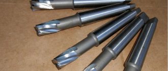
2) Smooth and stepped holes of parts having the shape of bodies of revolution. In most cases, they are made on lathes by drilling, reaming, countersinking or boring.
3) Critical openings of body parts. They are manufactured using both universal and specialized equipment and correspond to the seventh qualification and higher.
4) Deep holes having more than five times the length to diameter ratio. They are manufactured on specialized equipment.
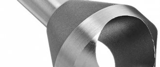
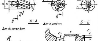
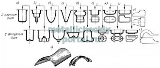
5) Shaped and conical holes. They are manufactured using tools with curved or conical cutting edges, as well as copying and boring methods.
6) Profile holes (having a cross-section other than round). They are made by chiseling, stitching or drawing.
Internal thread cutting technology
As mentioned above, before starting work, you need to drill a hole, the diameter of which must exactly fit a thread of a certain size. It should be borne in mind: if the diameters of the holes intended for cutting metric threads are chosen incorrectly, this can lead not only to poor quality execution, but also to breakage of the tap.
Considering the fact that the tap, when forming threaded grooves, not only cuts the metal, but also pushes it, the diameter of the drill for making threads should be slightly smaller than its nominal diameter. For example, a drill for making M3 threads should have a diameter of 2.5 mm, for M4 - 3.3 mm, for M5 you should choose a drill with a diameter of 4.2 mm, for M6 threads - 5 mm, M8 - 6.7 mm, M10 - 8.5 mm, and for M12 - 10.2.
Table 1. Main diameters of holes for metric threads
Table 2. Diameters of holes for inch threads
All diameters of drills for GOST threads are given in special tables. Such tables indicate the diameters of drills for making threads with both standard and reduced pitches, but it should be borne in mind that holes of different diameters are drilled for these purposes. In addition, if threads are cut in products made of brittle metals (such as cast iron), the diameter of the thread drill obtained from the table must be reduced by one tenth of a millimeter.
You can familiarize yourself with the provisions of GOST regulating the cutting of metric threads by downloading the document in pdf format from the link below.
The diameters of drills for metric threads can be calculated independently. From the diameter of the thread that needs to be cut, it is necessary to subtract the value of its pitch. The thread pitch itself, the size of which is used when performing such calculations, can be found out from special correspondence tables. In order to determine what diameter the hole needs to be made using a drill if a three-start tap is used for threading, you must use the following formula:
To = Dm x 0.8, where:
Do is the diameter of the hole that must be made using a drill,
Dm is the diameter of the tap that will be used to process the drilled element.
Scheme of cutting internal threads with a tap
The drivers into which the threaded tap is inserted can have a simple design or be equipped with a ratchet. You should work with such devices with tools fixed in them very carefully. To obtain high-quality and clean threads, rotating the tap clockwise, performed half a turn, must be alternated with turning it one-fourth of a turn against the thread.
The thread will be cut much easier if you use a lubricant during this procedure. The role of such a lubricant when cutting threads in steel products can be played by drying oil, and when processing aluminum alloys - alcohol, turpentine or kerosene. If such technical fluids are not at hand, then ordinary machine oil can be used to lubricate the tap and the thread being cut (however, it has less effect than the substances listed above).
Source: met-all.org
News
We accept orders for the production of individual heating points ITP
A heat distribution or heat point is a set of equipment and instrumentation designed to distribute heat supplied from an external heating network (boiler houses or thermal power plants) between heating, hot water supply or ventilation systems of industrial and residential facilities, cottages, offices, garages or others buildings taking into account the established parameters. 02 February 2022
Design and manufacture of heating points ITP
A heat distribution or heat point is a set of equipment and instrumentation designed to distribute heat supplied from an external heating network (boiler houses or thermal power plants) between heating, hot water supply or ventilation systems of industrial and residential facilities, cottages, offices, garages or others buildings taking into account the established parameters. January 15, 2022
Temporary interruptions in telephone lines
Dear Customers, colleagues and partners! During the period from November 18 to 19, there may be temporary interruptions in the operation of the toll-free telephone line 8-800-200-0357. November 18, 2022
The old-fashioned way: how to choose a drill for a tap
Good afternoon, dear readers!
I don’t know if you have ever encountered such a tool as a tap. But, if you work with fasteners, then sooner or later you will encounter this. Even if you are not a builder, you can experience the usefulness of this tool.
So, let's ask Wikipedia: what is a tap?
Metchik
- a tool for cutting internal threads, is a screw with cut straight or helical chip grooves that form cutting edges.
That is, the convenience is that you can drill a hole in the metal and cut a thread there, so that you can then screw in the threaded fasteners.
However, while taps are strong, they are not designed to make a hole. Therefore, you first need to make a hole
.
And here the difficulty lies in the fact that it is important not to make a mistake in the diameter of the drill
.
If you make the hole larger, the thread will turn out small and will quickly become beveled (or there will be no room for the thread at all), if you make it smaller, the tap will lock. And that is not all. The thread pitch on taps can be different, so each step will have its own drill diameter
.
Constantly carrying a table with you that indicates the required drill diameters is also not always convenient. Therefore, I offer you the old-fashioned way of how to select a drill for a tap
!
To make it more clear, let's look at an example:
- So you purchased bolts with a basic metric pitch of M8
.
Their pitch is: 1.25
. - Now you need to take a tap 8*1.25
. - Subtracts the second value from the first
: 8-1.25.
It turns out 6.75
. - But there are no 6.75 drills, so we round up
half
a millimeter .
It turns out 6.8
. - It turns out that in order to successfully cut a thread for 8*1.25
, you need to use
a 6.8 mm drill
.
Everything is extremely simple!
If you liked the article, then like it! And for those who have not yet subscribed to the channel, I recommend subscribing, because there is still a lot of useful information ahead!
Source: zen.yandex.ru