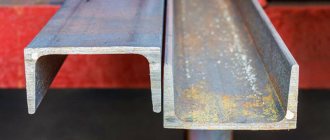
How to weld a channel without losing the strength of the seam
In construction, a channel is used to increase the load on the supporting and load-bearing structures of a building. Often channels are connected to each other to increase their load-bearing area. Of course, a better method of welding for connecting channels has not yet been invented, so this is what we will talk about.
Welding channels is a critical step, since the safety of the entire structure depends on the strength of the connection. Therefore, when carrying out this process, welders adhere to strict rules and GOST.
Methods for welding channels together according to GOST
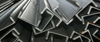
A channel is one of the main elements that make up a metal structure. To form the desired frame structure, welding of channels is required. The welded assembly has good reliability, but any violations in the welding technology can lead to weakening of the entire structure. In this regard, welding is the most difficult and controlled stage in the production of metal structures.
No. 3. Requirements for stairs
Let's start with the fact that all the stairs you've ever seen differ in type of construction:
- marching stairs – the simplest, most popular and comfortable. A march is a continuous series of steps. For maximum convenience, it is recommended to make no more than 17 steps in one flight, and if it is necessary to provide a larger number of them, then it is better to additionally equip the interstaircase area. Marching stairs can be straight (for self-arrangement - just right) and rotary. The latter allow you to save space without losing comfort. Among the marching ladders there are ladders on stringers and on a bowstring. The stringers have a stepped, sawtooth shape and are located under the steps. Bowstring - an inclined beam, steps are inserted into grooves;
- ladders on rails fastened to the wall with bolts or bolts. Outwardly, it seems that the steps are floating in the air, but this does not affect the strength of the structure in any way, the main thing is that the wall withstood such a load;
- spiral staircases assume the presence of a support pillar around which steps are arranged in a spiral. In terms of convenience, it is inferior to other types of stairs, but it allows you to save a lot of space.
When they talk about the production of a metal frame, they usually mean marching stairs. However, the metal frame does not have to be sheathed - it can remain visible, but then it is better to make it from a profile or even sheets of metal (for the loft style, for example).
Going up and down the stairs should be comfortable, so:
- the optimal width of the stairs is 80-90 cm (definitely at least 70 cm). If it is more, then you will have to strengthen the structure so that the steps do not sag;
- optimal slope angle – 30-45 degrees, an angle of 50 degrees is called critical, and anything even larger is attic and extension ladders; they are not intended for permanent use;
- the optimal step height is 15 cm, but in practice this can be difficult to achieve. Stairs with step heights up to 19 cm are also quite comfortable;
- optimal step width - 30 cm (at least 27 cm for sure), but even this is difficult to achieve in conditions of limited space, so they often resort to a trick, increasing the area of each step due to the protruding part above the bottom step. The length of the protruding part should not be more than 5 cm, and the free space (without overhang of the upper element) should be at least 10 cm;
- the corner and channels are connected by welding or threading. The first option is the most preferable; it allows you to obtain a more durable structure. Emergency and fire escapes can be further reinforced.
As practice suggests, a staircase that is ideal in terms of all parameters can be built only when there is a lot of space allocated for it , for example, in the entrance of an apartment building. In all other cases, you have to look for compromise options and experiment.
Types of joining channels
The choice of connection is directly proportional to the size of the structure and the forces acting on it.
The following options for the relative arrangement of channels are distinguished:
- the channel shelves are facing inward;
- the channel flanges face outward (forms an I-beam);
- mixed arrangement of shelves;
- the channel flanges are perpendicular to the plane of the frame;
- diagonal placement (standing or lying down).
The choice of a particular option is associated with:
- suture conditions;
- the length of the welding site and the number of workers involved to apply it;
- type of forces and places of their influence;
- type and overall dimensions of the channel;
- the required design stability and full load on the structure.
How to calculate parameters
The dimensions of the stairs are calculated using the following algorithm:
- Determine the height and parameters of the opening.
- Create a projection of the future structure.
- The angle of inclination is measured (should be from 30 to 45 degrees), and based on the result obtained, the length of the stairs is determined.
- Determine how to strengthen the stairs. To ensure sufficient strength, its width must be at least 90 cm. This is necessary in order to prevent the occurrence of deflection.
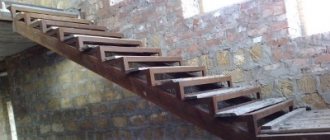
You can make a staircase from corners with your own hands. The procedure depends on the type of structure planned, the materials used and the area that the owner of the residential premises can allocate. At the first stage, the master must prepare the necessary parts. The second step is to build the frame and finish it. The third step is to give it a decorative look.
The owner himself decides on the design solution. A metal staircase made from a channel and a corner can be installed outside or inside the house. The basement is no exception.
Types of welding used
Arc welding
A huge selection of types of electrodes according to their nominal characteristics and the features of their operation provide an undeniable advantage over other types of welding and make it preferable for this task. We will get the best seam if we use UONI electrodes. When working with these electrodes, you should take into account their features and recommendations:
- Where possible, connections should be overlapped.
- To use this electrode, prior experience with it is required.
- Before use, the electrode must be calcined in a special. oven for an hour. Calcination temperature 250 C.
- The joints of products must be cleaned of dirt, rust and prepared in accordance with GOST 5264-80.
- The welder must work with a short arc of medium power, direct current and reverse polarity.
- Metal structures welded with this electrode should not be used at temperatures below – 40 C.
Gas welding
This type is often not used when welding channels due to the huge area and heating temperature. These factors are a source of internal stresses in the metal structure and general deformations that negatively affect the entire metal structure. Nevertheless, gas welding is often used to eliminate flaws in finished structures or to cut workpieces and then remove edges.
Technologies used
There are several technologies suitable for high-quality channel welding. But we will tell you about the most convenient and frequently used one, in our opinion.
Arc welding
Electric arc technology is the undisputed leader. And all because manufacturers offer a wide range of electrodes for working with a wide variety of types of metals. In addition, electric arc welding can be carried out in the most difficult to reach places, including at heights. Of course, provided that the welding machine is compact and can be hung on your shoulder.
Welding types
Butt welding of channels
This connection is used for non-critical structures. Welding is performed from the front and back sides and with the condition of good penetration thickness. The installation seam is first performed on the thin and then on the thicker part of the channel. It is allowed to make this seam on one side of the product with the obligatory welding of the root of the seam.
Sequence of sutures
The need for edge removal is determined based on the thickness of the channel flanges:
- 6 mm or less - no bevel of edges required.
- 6-12 mm - the bevel is made at an angle of 30.
- 12 mm and more - the bevel of the edges is made at an obtuse angle on the inside of the workpiece. The seam is made V and X-shaped.
Welding algorithm:
- The channel is placed horizontally with its walls.
- The edges are removed depending on the thickness of the metal.
- Two beams are joined with a gap of no more than 3 mm.
- The workpieces are temporarily tacked together at points in increments of 40 mm.
- The correctness of the created design is analyzed.
- The final welding of the joint surface is carried out continuously from the middle of the wall towards the shelves.
To improve welding characteristics and prevent the appearance of cracks at welding points, it is recommended to reinforce the rolled steel with pads immediately after installing the product. When welding U-shaped bars only at the butt, without overlays, the welded joint will be weaker than the channel itself.
Welding channels with overlays
The gap at the junction of two welded parts is set to no more than 8 mm. The overlay is placed on the side of the weld. The thickness of the reinforcement depends on the welding mode and the size of the rolled product.
It is necessary to go around the reinforcement pads with an electrode along the entire plane. If circular scalding is not possible, fill all gaps with a substance that prevents corrosion.
Welding algorithm:
- The channels are welded end to end in accordance with GOST technological standards.
- The seam inside the channel is smoothed to a plane.
- A reinforcement is welded into the inner part of the channel - a sheet of steel having a length equal to 5 times the width of the channel. The width of the sheet is equal to the width of the channels, the thickness of the sheet is taken equal to the thickness of the channel material. The strip is welded only on the longitudinal sides.
- The second strip is attached as a rib and welded on both sides of the strip. The rib should be well cooked along the contour on both sides and close to the strip.
The strength characteristics of a product spliced using this method will be slightly inferior to a monolith.
Connecting channels inwards
To create a reinforced hollow beam, you can connect two products with shelves inward. Making such a connection is the same as butt welding two channels. This connection is used when medium power structures are required.
Welding algorithm:
- Place the workpieces on shelves horizontally opposite each other.
- Secure with clamps.
- Make the seam either according to GOST with separation of the edges, or leave a gap (the size of the gap is chosen depending on the thickness of the channel, but not less than 3 mm).
- The seam must be made using the tack method or from the middle to the edges.
Attention
Cleaning the seams with a grinder in this connection is strictly prohibited and can lead to weakening of the entire structure.
It is possible to assemble this configuration in conditions unsuitable for this work when assembling the structure only when welding is carried out in a horizontal plane and in a lower position. In other cases, it would be more reasonable and simple to use butt seams with their reinforcement with lining sheets.
Offset connection
This welded structure is produced by several welders and is used to combine channels with different geometric dimensions. Welding begins from places with thicker metal. Butt joints are made in accordance with standard standards, and corner joints must be made simultaneously with two welds (from edge to middle). Longitudinal seams cannot be applied to the end of the beam. This distance depends on the materials being joined and the area of the rolled shelf. For carbon steels, this distance is equal to the width of the flange, and for alloy metals it is equal to twice its width.
When assembling metal structures of varying degrees of complexity and configuration, the methods and types of welding channels listed above are used. Any metal structure can be divided into separate small independent node connections in which the above methods will be applicable.
The most durable connection method among all types is considered to be the connection of equal-flange bars with parallel flanges.
Any welding of channels or I-beams requires compliance with a predetermined series of actions and the exact order of installation work. The assembly of any metal structure should always begin from the middle and move towards the edges; at the same time, welding begins with channels having a thicker metal profile. When assembling, it is not recommended to place welds close to each other; it is better to strengthen these places using backing sheets of metal and auxiliary reinforcing structures. Any weld itself reduces the strength of the entire metal structure by 5-7 percent, although the material of the weld has better strength characteristics than the material of the main part. The welding mode and the speed of applying the weld directly depend on the type of connection you choose, but the best when working with manual electric welding is considered to be 20 m/h.
To create an excellent, strong connection, before welding it is necessary to thoroughly clean the areas of future connections and process the edges in accordance with GOST recommendations. Reinforcement strips after butt welding should only be placed on the outside of the channels. Welding in the inner corners of the channel will weaken the entire structure, so it is not advisable to carry out work in the inner corners of the unit.
Common connections
Butt welding
Channel butt welding is the favorite connection of all beginners.
It is used for practice or for welding non-critical structures. Can be done both from the front and from the inside. But when welding from the inside, you need to make sure that there are no lacks of penetration. Also, a seam can be formed only on one side, but in this case it is necessary to weld the root of the seam. If the thickness of the channel walls exceeds 6 millimeters, then it is necessary to cut the edges. The cutting can be V or X-shaped. The optimal angle is 30 degrees if the thickness is no more than 12 millimeters.
Let's start welding. To begin, join two channels with the walls facing each other. Docking should be as precise as possible; it is better to do it not by eye, but with the help of a special centralizer. The gap between two channels should not exceed 3 millimeters. To prevent the workpieces from moving in different directions during welding, you need to make a temporary tack. The tack is welded to both parts using weld points.
The seam must be drawn from the middle of the channels to the edges. Please note that this connection is not very reliable. To strengthen it, you can use overlays. We'll talk about this in more detail later.
Welding using pads
Welding channels with overlays is already more reliable than conventional butt welding. This is also proven by the fact that the gap between the channels can reach up to 8 millimeters. The plate itself must be placed on the side of the welded joint. The overlay is selected based on the thickness and size of the channels. The larger and thicker the channel, the stronger the lining should be. When welding, it is necessary to weld both sides of the lining.
Now more details. To choose an overlay you need to know the approximate dimensions of the channels that you are going to weld. We recommend dividing the channel length by 5. This will give you the recommended overlay length. The thickness of the overlay should be the same as the thickness of the channel. There should be two pads in total. From the inside and from the outside. In this case, the outer lining should be longer than the inner one.
Connection inwards
Sometimes channels are welded with “shelves” inward. The technique is the same as for butt welding, only there is either no gap or it is very small. Inward welding is more difficult to perform than butt welding. So this connection could be next in your educational practice.
Welding is performed as follows. Prepare the metal thoroughly before welding. Do not use an angle grinder, otherwise the connection will not be strong. Join the two channels horizontally and symmetrically. Secure them with clamps. It is advisable to make a seam with grooved edges, but sometimes a small gap is allowed. Welding is performed from the middle of the channel to its edges.
The main disadvantage of this method of welding channels is the need to work in ideal conditions. You will not be able to weld in hard-to-reach places. To ensure a high-quality seam, you need to cook it in a strictly horizontal lower position. If you cook under other conditions, then you will simply waste time, effort and components. It is more logical to weld end-to-end or using overlays.
In general, this connection is used infrequently. But if you have the opportunity to cook in a lower horizontal position, and you choose the place of butt welding and welding inside, then we recommend choosing the second option. It is still more reliable.
Offset connection
Offset connection of channels is a complex job that is performed by a whole team of welders. Such a connection is necessary in cases where it is necessary to weld different structures from channels, and at the same time these channels have different sizes.
Welding should begin from those places where the channels are thickest. It is necessary to combine different connections: end-to-end, corner, and longitudinal. Moreover, each connection will have its own nuances. Butt joints are performed simply and without problems, but corner joints must be performed by two welders at once. And when making longitudinal seams, they cannot be formed to the end of the channel.
Production and use
Due to their ability to withstand heavy bending loads in different planes, shear and torsion, steel I-beams form the basis of load-bearing structures of prefabricated frame buildings and ceilings.
In-shop lifting mechanisms (beam cranes and overhead cranes) move along guides made from I-beams.
The production of I-beams is carried out in two ways:
- method of rolling solid castings. Such I-beams are called hot-rolled;
- electric arc welding of pre-cut sheet blanks, resulting in a welded prefabricated I-beam.
Hot-rolled I-beams are produced on rolling mills of metallurgical enterprises. This technology makes it possible to obtain a one-piece product that does not contain seams and is highly durable.
Assembly and welding of I-beams is carried out on automatic lines. Such a beam is slightly inferior to a solid-rolled beam in terms of strength, but can be made to special order, taking into account the requirements of a specific project.
The production of hot-rolled I-beams is carried out in accordance with GOST 26020-83; manufacturers produce welded I-beams according to their own technical conditions (TU).
Possible defects
During welding of an I-beam, due to non-compliance with the technology, crystallization of the steel occurs due to high temperature. Due to phase discrepancies, internal stresses arise in the metal. Strength and rigidity decrease, and the risk of corrosion increases.
When welding steel sheets, other defects are possible:
- violation of the shape of the seam; deviation from the shape of the outer surfaces or the geometry of the joint;
- burns, when the melt flows out of the bath, holes form in the seam;
- undercuts – grooves along the joint boundary;
- cracks forming in places where the seam breaks;
- slag or tungsten inclusions in the diffusion layer; at high welding speeds, refractory oxides are formed.
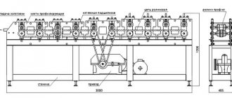
Welding beam joints using submerged arc machines.
Let's say a few words about automatic welding of joints. If the beam is welded under submerged arc using automatic welding machines, then different techniques may be used, just as the sequence may differ.
Welding can be carried out with an inclined electrode, which allows you to make two seams at the same time. On the other hand, this method also has disadvantages. When the electrode is tilted, the risk of cutting off the flanges or walls of the beam increases.
In addition, seams can be performed in a position called by specialists, “boat”. This creates better conditions for seam formation, penetration, etc. However, among the disadvantages of this method is the need to rotate the product after each welded joint. This disadvantage is solved by using special positioners-tilters.
The process of welding beam joints requires careful preparation, carrying out and checking calculations of moments of inertia, bending moment, etc.
It is important to follow the beam welding technology, the incorrectness of which can affect the future metal structure as a whole