Over a long period of use, pipelines are exposed to negative external and internal environmental influences.
As a result, the metal degrades, corrosion formations form on it, cracks and chips appear, and other types of defects. It would seem that when creating a pipeline project using modern technologies, complete protection of main communications should be ensured. But, unfortunately, it is impossible to completely exclude the occurrence of damage. To prevent small defects from becoming a serious problem, various types of control are used.
One of them, which does not involve the removal of the main system for repair, is pipeline flaw detection.
This diagnostic method has become widespread. Its use makes it possible to identify the following types of defects:
- loss of tightness level;
- loss of control over the state of tension;
- violation of welded joints;
- depressurization of welds are other parameters that are responsible for the reliable functioning of highways.
You can check this way:
- heating network;
- gas supply network;
- oil pipelines;
- water supply pipelines, etc.
Flaw detection is 100% capable of identifying deficiencies and preventing serious accidents. Methods for searching for defects are constantly being improved, equipment is updated, and new models of flaw detectors are tested. Plus, to all this, various analyzes are carried out in order to subsequently improve the performance of the funds.
General information
Pipeline diagnostics consists of several technologies that are divided into two main groups: destructive and non-destructive. When using the first, the joint of two pipes is destroyed, after which the edges of the connected sections are examined for quality and detection of defects. This option is possible if the pipeline is being repaired (completely shutting it down).
The second technology does not require destruction, which makes it possible to carry out control at existing sites. It is used everywhere today, especially in the field of oil and gas transportation, plus housing and communal services. Such flaw detection, as non-destructive testing is called, is carried out to determine defects in pumping stations, tanks for various purposes, at liquefied gas plants and other enterprises.
Are you familiar with this concept?
Yes, I have repeatedly carried out flaw detection of metal pipes at home.
100%
No, this is the first time I've heard of it.
0%
Voted: 1
Prices for services
| No. | Measurable indicator of the tested product | Scope of work included in product testing | Regulatory document | Cost, rub., incl. VAT 18% |
| Weld inspection | ||||
| 1 | Ultrasonic testing of welded joints with a thickness of 0 - 10 mm (1 lm) | — Preparing and setting up equipment — Carrying out control — Processing results — Keeping logs — Drawing up protocols | GOST R 55724-2013 SP 70.13330.2012 | 1 000 |
| 2 | Ultrasonic testing of welded joints with a thickness of 10 - 20 mm (1 lm) | — Preparing and setting up equipment — Carrying out control — Processing results — Keeping logs — Drawing up protocols | GOST R 55724-2013 SP 70.13330.2012 | 1 200 |
| 3 | Ultrasonic testing of welded joints with a thickness of 20 - 30 mm (1 lm) | — Preparing and setting up equipment — Carrying out control — Processing results — Keeping logs — Drawing up protocols | GOST R 55724-2013 SP 70.13330.2012 | 1 500 |
| 4 | Ultrasonic testing of welded joints with a thickness of 30 - 40 mm (1 lm) | — Preparing and setting up equipment — Carrying out control — Processing results — Keeping logs — Drawing up protocols | GOST R 55724-2013 SP 70.13330.2012 | 2 000 |
| 5 | Ultrasonic and visual quality control (flaw detection) of welded joints of reinforcement (1 joint) | — Preparation and setup of equipment — Conducting control — Processing results — Drawing up protocols | RD 03-606-03 GOST 23858-79 GOST R 55724-2013 | 700 |
| 6 | Ultrasonic flaw detection with one transducer of pearlite class welded joints on both sides, transverse sounding. Pipelines with a diameter of up to 36 mm, wall thickness up to 6 mm. (1 joint) | — Preparing and setting up equipment — Carrying out control — Processing results — Keeping logs — Drawing up protocols | GOST R 55724-2013 RD 153-34.1-003-01 | 590 |
| 7 | Ultrasonic flaw detection with one transducer of pearlite class welded joints on both sides, transverse sounding. Pipelines with a diameter of up to 57 mm, wall thickness up to 6 mm. (1 joint) | — Preparing and setting up equipment — Carrying out control — Processing results — Keeping logs — Drawing up protocols | GOST R 55724-2013 RD 153-34.1-003-01 | 630 |
| 8 | Ultrasonic flaw detection with one transducer of pearlite class welded joints on both sides, transverse sounding. Pipelines with a diameter of up to 76 mm, wall thickness up to 6 mm. (1 joint) | — Preparing and setting up equipment — Carrying out control — Processing results — Keeping logs — Drawing up protocols | GOST R 55724-2013 RD 153-34.1-003-01 | 680 |
| 9 | Ultrasonic flaw detection with one transducer of pearlite class welded joints on both sides, transverse sounding. Pipelines with a diameter of up to 89 mm, wall thickness up to 6 mm. (1 joint) | — Preparing and setting up equipment — Carrying out control — Processing results — Keeping logs — Drawing up protocols | GOST R 55724-2013 RD 153-34.1-003-01 | 720 |
| 10 | Ultrasonic flaw detection with one transducer of pearlite class welded joints on both sides, transverse sounding. Pipelines with a diameter of up to 108 mm, wall thickness up to 8 mm. (1 joint) | — Preparing and setting up equipment — Carrying out control — Processing results — Keeping logs — Drawing up protocols | GOST R 55724-2013 RD 153-34.1-003-01 | 690 |
| 11 | Ultrasonic flaw detection with one transducer of pearlite class welded joints on both sides, transverse sounding. Pipelines with a diameter of up to 114 mm, wall thickness up to 8 mm. (1 joint) | — Preparing and setting up equipment — Carrying out control — Processing results — Keeping logs — Drawing up protocols | GOST R 55724-2013 RD 153-34.1-003-01 | 790 |
| 12 | Ultrasonic flaw detection with one transducer of pearlite class welded joints on both sides, transverse sounding. Pipelines with a diameter of up to 159 mm, wall thickness up to 8 mm. (1 joint) | — Preparing and setting up equipment — Carrying out control — Processing results — Keeping logs — Drawing up protocols | GOST R 55724-2013 RD 153-34.1-003-01 | 960 |
| 13 | Ultrasonic flaw detection with one transducer of pearlite class welded joints on both sides, transverse sounding. Pipelines with a diameter of up to 219 mm, wall thickness up to 8 mm. (1 joint) | — Preparing and setting up equipment — Carrying out control — Processing results — Keeping logs — Drawing up protocols | GOST R 55724-2013 RD 153-34.1-003-01 | 1 160 |
| 14 | Ultrasonic flaw detection with one transducer of pearlite class welded joints on both sides, transverse sounding. Pipelines with a diameter of up to 273 mm, wall thickness up to 8 mm. (1 joint) | — Preparing and setting up equipment — Carrying out control — Processing results — Keeping logs — Drawing up protocols | GOST R 55724-2013 RD 153-34.1-003-01 | 1 280 |
| 15 | Ultrasonic flaw detection with one transducer of pearlite class welded joints on both sides, transverse sounding. Pipelines with a diameter of up to 325 mm, wall thickness up to 8 mm. (1 joint) | — Preparing and setting up equipment — Carrying out control — Processing results — Keeping logs — Drawing up protocols | GOST R 55724-2013 RD 153-34.1-003-01 | 1 480 |
| 16 | Ultrasonic flaw detection with one transducer of pearlite class welded joints on both sides, transverse sounding. Pipelines with a diameter of up to 377 mm, wall thickness up to 8 mm. (1 joint) | — Preparing and setting up equipment — Carrying out control — Processing results — Keeping logs — Drawing up protocols | GOST R 55724-2013 RD 153-34.1-003-01 | 1 920 |
| 17 | Ultrasonic flaw detection with one transducer of pearlite class welded joints on both sides, transverse sounding. Pipelines with a diameter of up to 426 mm, wall thickness up to 10 mm. (1 joint) | — Preparing and setting up equipment — Carrying out control — Processing results — Keeping logs — Drawing up protocols | GOST R 55724-2013 RD 153-34.1-003-01 | 2 240 |
| 18 | Ultrasonic flaw detection with one transducer of pearlite class welded joints on both sides, transverse sounding. Pipelines with a diameter of up to 530 mm, wall thickness up to 10 mm. (1 joint) | — Preparing and setting up equipment — Carrying out control — Processing results — Keeping logs — Drawing up protocols | GOST R 55724-2013 RD 153-34.1-003-01 | 2 560 |
| 19 | Ultrasonic flaw detection with one transducer of pearlite class welded joints on both sides, transverse sounding. Pipelines with a diameter of up to 720 mm, wall thickness up to 8 mm. (1 joint) | — Preparing and setting up equipment — Carrying out control — Processing results — Keeping logs — Drawing up protocols | GOST R 55724-2013 RD 153-34.1-003-01 | 2 760 |
| 20 | Ultrasonic flaw detection with one transducer of pearlite class welded joints on both sides, transverse sounding. Pipelines with a diameter of up to 820 mm, wall thickness up to 14 mm. (1 joint) | — Preparing and setting up equipment — Carrying out control — Processing results — Keeping logs — Drawing up protocols | GOST R 55724-2013 RD 153-34.1-003-01 | 2 920 |
| 21 | Ultrasonic flaw detection with one transducer of pearlite class welded joints on both sides, transverse sounding. Pipelines with a diameter of up to 1020 mm, wall thickness up to 14 mm. (1 joint) | — Preparing and setting up equipment — Carrying out control — Processing results — Keeping logs — Drawing up protocols | GOST R 55724-2013 RD 153-34.1-003-01 | 3 200 |
| 22 | Ultrasonic flaw detection with one transducer of pearlite class welded joints on both sides, transverse sounding. Pipelines with a diameter of up to 1220 mm, wall thickness up to 14 mm. (1 joint) | — Preparing and setting up equipment — Carrying out control — Processing results — Keeping logs — Drawing up protocols | GOST R 55724-2013 RD 153-34.1-003-01 | 3 760 |
Make an order
Details
There are several pipeline flaw detection technologies. The simplest of them is a visual inspection.
You can determine by the appearance of the weld whether it is of high quality or not. If joint defects are not visible, then a magnifying glass is used to find them. Sinkholes, irregularities, cracks - all these are flaws in the weld, which indicates the low quality of the welding work performed.
This control method is rarely used in existing pipelines. Most often as a complement to other types. It is the latter that are the basis for quality control.
The main methods used today:
- ultrasonic flaw detection of pipelines;
- magnetic;
- radiation;
- capillary;
- permeability test.
Visual
Using this type of control, you can detect not only external defects, but also internal ones. For example, if the seam has a serious deviation in height and width, then most likely the arc was interrupted during the welding process. This means that lack of penetration may appear inside the seam, reducing the quality of the connection.
You can detect such flaws like this:
- clean the seam from scale, drops, slag;
- it is further cleaned with alcohol;
- Nitric acid is applied to the seam area - a process called etching;
- The seam is examined using a magnifying glass.
Etching makes the metal surface clean and matte. Even minor imperfections are clearly visible on it. Usually attention is paid to cracks. Burns, undercuts, and other defects are also clearly visible.
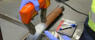
Ultrasonic flaw detection
This is one of the most accurate options for flaw detection of pipelines, storage vessels and other structures. The technology is based on the property of ultrasound to be reflected from surfaces, as well as materials that have different densities. If the welding seam was made with high quality, then the density of the metal poured between the edges of the pipes will be the same throughout the entire volume. And when ultrasonic flaw detection is carried out, the sound will pass through the seam unhindered.
If there is a pore or cavity inside the metal, then there is always some kind of gas inside it. The density inside the flaw is clearly less than that of the metal. And when ultrasound passes through metal, it encounters a void along its path. The sound travels through the gas, hits the wall of the sink and returns back. It is the backward wave that indicates that there is a defect inside the seam.
Different voids reflect ultrasound differently. This allows them to be classified. That is, it is a sink, a crack or something else.
Purely technically, this method of pipeline flaw detection is a special device in the form of rings, which are often called gratings. They are put on the pipe and then connected to an ultrasound source. The rings transmit inward waves and receive reflected ones.
The more defects there are inside the metal, the more reflected waves are returned to the receiver of the pipeline flaw detection device. In this case, the distinctive feature of each defect is the length of the returned wave.
There are many tasks that are posed to ultrasonic flaw detection.
Therefore, several effective methods have been developed that are used today to solve each:
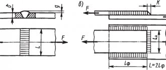
- shadow;
- mirror;
- mirror-shadow;
- echolocation;
- delta method.
Today, instruments used for ultrasonic examination of pipelines are equipped with different devices in accordance with the required control methods. One may have several weld inspection technologies. Therefore, before starting work, the operator selects and establishes a troubleshooting method. Or uses several options at once.
Magnetic flaw detection of pipelines
This method is based on electromagnetic induction (creating a magnetic field in the weld metal). For this purpose, the equipment that this field creates is used.
There are two technologies for performing flaw detection of this type:
- Using ferromagnetic powder. Usually iron is used for this.
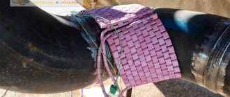
- Using ferromagnetic tape.
In the first case, the powder is simply poured into the control area. It can be dry or mixed with oil or kerosene. A magnet is installed on the back of the pipe. If in some place the powder begins to gather in piles, it means there is a metal defect.
In the second case, instead of powder, a special tape is laid. A device that generates a magnetic field is installed on the reverse side of the seam. In areas where there are flaws inside, spots will appear on the tape.
This method of flaw detection of pipelines can be used if the pipes are made of ferromagnetic alloys (which attract a magnet). Non-ferrous metals, austenitic stainless steel, steel coated with nickel or chromium are not subject to this control method.
Radiation flaw detection of pipelines
This method is conventional fluoroscopy, which uses a compact X-ray machine and film. The method is expensive, but the most accurate of all those proposed. However, X-rays are dangerous to humans.
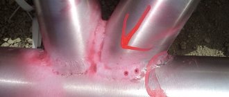
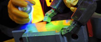
Penetrant flaw detection
This method is based on the property of certain liquids, called penetrants, to penetrate capillaries in any material. It doesn't have to be metal. This way you can check glass, plastic, ceramics, etc.
The essence of the flaw detection method is that a penetrating liquid is applied to the controlled section of the pipeline. After some time, usually 20 minutes, it is removed, and an indicator is applied to the same area, which begins to draw penetrant out of the seam defects. If after the operation no traces of penetrants are found, then there is no flaw in the pipe joint.
Of the penetrating liquids, the simplest is kerosene. To use it, you must clearly know the application technology. It should be done like this:
- a liquid chalk solution is applied on the outside;
- it must dry;
- kerosene is applied on the reverse side;
- If wet lines or spots appear on the chalk mortar side, it means there are defects in the metal.
Flaw detection of connections for permeability
This method is used to control the quality of welds on tanks and containers. To do this, they are filled with liquid or gas, and then excess pressure is created inside. The environment begins to look for a way out, and if there are cracks or other flaws in the seams, then it quickly begins to seep out through them.
The effectiveness of the method increases if a soap solution is distributed over the joints from the outside. Especially if the tank is filled with gas. Bubbles at the joints will indicate that the seams were welded poorly.
Advantages and disadvantages of ultrasonic pipe inspection
Main advantages of ultrasonic pipe inspection:
- minimum time for inspection;
- high accuracy of examination results;
- absolute safety for human health;
- the inspection is carried out without damaging the part being examined;
- possibility of checking joints of stainless, ferrous and non-ferrous metals.
It is worth noting separately that ultrasonic testing devices are small in size, so welds can be checked not in a laboratory, but directly on a construction site or in the workshops of an industrial enterprise. This is very convenient for monitoring seams during construction or installation work.
However, in addition to the advantages, ultrasound diagnostics also has several significant disadvantages. First of all, this concerns the inspection results. It is not always possible for an operator to determine the shape of a defect found when examining welded joints of metal with a coarse-grained structure. This occurs due to strong attenuation and scattering of the ultrasonic wave, which makes it difficult to identify the shape of the defect. Another important disadvantage of this technique is the need for thorough cleaning of welded joints. Many novice specialists do not always approach this procedure responsibly. As a result, waviness or contamination, rust or scale, droplets of spattered metal or air saddles, and even small pores on the surface of welds make it difficult to obtain objective data on the quality of the weld. In addition, ultrasound cannot always be used to inspect parts with complex configurations. The natural curvature of the part affects the inspection results, preventing one from obtaining correct information about internal flaws in the welds.
Equipment for flaw detection of pipelines
Modern flaw detection technologies are mainly in-line diagnostics. For this purpose, special equipment is used, called in-line flaw detectors. They are placed inside the pipeline and brought to the required areas, where they independently carry out control. Many of them are equipped with cameras: photos and videos.
With their help they determine:
- cross-sectional shape of the pipe;
- presence of corrosion;
- dents;
- whether there has been any thinning of the metal or other flaws.
Some devices move through the pipeline due to the moving flow. Some are due to the installed electric motor. There are sensors inside, the function of which is to accumulate and store the received information.
In-line flaw detection of main pipelines is a technology that eliminates the need to use equipment that conducts systematic research. At the same time, the inspection speed is higher than all known flaw detection methods. But this option is used only in large-diameter pipelines.
Pipeline research using this method is carried out in several stages:
- preparation, also known as diagnostics;
- cleaning measures of the internal space of the pipeline;
- calibration is ensuring the internal patency of pipes;
- using a profiler - this way bends, turns and other irregularities are examined;
- the use of ultrasonic flaw detection and magnetic;
- determination of pipeline safety.
Types of detected defects
Using this type of flaw detection, you can identify various defects, for example:
- Dents, chips and other geometric inconsistencies. To do this, an electronic-mechanical probe touches the pipe walls. The device converts the electrical signal and records the information received.
- Thinning of the metal, due to which the wall thickness of the route is reduced. These are corrosion, cracks.
- Transverse and longitudinal defects.
To record all discrepancies, the speed of movement of the device is controlled. After removing the flaw detector, a specialist analyzes the information and draws up a report. The timing of prevention and repair is selected individually, taking into account the characteristics of the route and the recommendations of the expert.
Results
Metal degradation is a serious problem, especially in structures in which various media move under high pressure. Over time, the strength of the connecting areas decreases, which can lead to serious consequences. The problem today is solved simply - by control, for which various methods of pipeline flaw detection are used.
Each of the above methods has its pros and cons. But they guarantee high detection accuracy, which is required during control inspections. Therefore, newly introduced pipelines are subject to mandatory inspection. Operated ones are checked according to a strictly approved schedule of preventive maintenance. It is impossible to violate the deadlines for flaw detection under any pretext.
Ultrasonic flaw detection of a weld: video.
What do you think, which of the proposed methods is the most informative? Write in the comments. Save the article to bookmarks and share it on social networks.
Results Evaluation Options
The quality of the work performed is directly affected by the sensitivity of the device, which allows you to accurately recognize the parameters of the defect. First of all, using an ultrasonic flaw detector, the number of flaws that can lead to destruction of the weld and the entire metal structure as a whole is determined. The assessment of defects located in the weld is carried out according to the following criteria:
- acoustic wave amplitude;
- conditional wave length;
- size of the defect and its shape.
To determine the length of the wave and the width of the defect, it is necessary to carefully move the emitter along the weld joint. To determine the height of an internal crack or cavity, it is necessary to take into account the time intervals between the reflected and emitted waves. It is worth noting that the process of identifying the form of a defect requires a highly qualified operator, so it is better to entrust this work to specialists who have undergone appropriate training.
Story
- Jacques and Pierre Curie in 1880-1881 discovered a reversible piezoelectric effect, which made it possible to use quartz as a converter of electrical vibrations into sound
- The first flaw detector for detecting damage in an electrical circuit was developed by Dmitry Aleksandrovich Lachinov in the late 1880s - Lachinov Flaw Detector
- Lord Rayleigh in 1885-1910 developed the theory of sound propagation in solids
- The pulse-echo method was first used by Langwen and Shilovsky with piezoelectric transducers in an aqueous environment in 1915-1917
- In 1922, a magnetic method for detecting defects in artillery barrels using magnetic powder, discovered by William E. Hawk during World War I, was patented
- The first flaw detectors operating on continuous sound were created in 1928 by S. Ya. Sokolov and in 1931 by Mühlhäuser
- 1937-1938 - the world's first installation using alternating current to control railway structures and wheel sets (MAGNAFLUX company, USA)
- Echo-pulse flaw detectors (principle of operation and device) were created for the first time in 1939-1942 by Firestone in the USA, Sprules in the UK and Kruse in Germany
- The first echo-pulse flaw detectors were released in 1943 almost simultaneously (Danberry, USA) and Kelvin and Hughes Ltd. (London)
Magnetic Powder Flaw Detectors
The flaw detector allows you to control parts of various shapes, welds, internal surfaces of holes by magnetizing individual controlled areas or the product as a whole with a circular or longitudinal field created using a set of magnetizing devices powered by pulsed or direct current, or using permanent magnets. The principle of operation is based on the creation of a stray field over defects in the part being tested, followed by their detection by a magnetic suspension. The highest density of magnetic field lines of the stray field is observed directly above a crack (or other discontinuity) and decreases with distance from it. To detect discontinuities, magnetic powder suspended in air (dry method) or liquid (wet method) is applied to the surface of the part. The particle in the stray field will be subject to the following forces: a magnetic field directed to the region of the highest density of magnetic field lines, that is, to the location of the crack; heaviness; buoyant action of liquid; friction; forces of electrostatic and magnetic interaction that arise between particles.
In a magnetic field, particles are magnetized and connected into chains. The resulting force attracts particles to the crack and accumulates above it, forming a powder accumulation. The width of the strip (roller) of settled powder is significantly greater than the width of the crack opening. The presence of defects is determined by this precipitation—an indicator pattern.
Radiation method
To control the quality of welding, radiation methods and devices are used. In essence, this is the same X-ray machine used in hospitals, or a device with a gamma radiation source, adapted for irradiating welded joints.
It is based on the ability of these rays to penetrate any materials. The intensity of penetration depends on the type of substances being tested. Thanks to this, an image characterizing the condition of this material remains on the photographic film behind the product under study.
All welding defects in the form of inhomogeneities are revealed on the film. The control method is very accurate, but expensive and harmful to people; it requires preparatory work to install protective screens and carry out organizational measures.
Scope of application of ultrasonic testing
This control method is used in the industrial sector, as well as in the reconstruction and construction of houses. Ultrasonic testing is often used:
- For analytical diagnostics of units and components.
- To determine the wear of pipes in the main pipeline.
- In nuclear or thermal energy.
- In the field of mechanical engineering, oil and gas, chemical industries.
- When checking welds of structures with complex configurations.
- When diagnosing metal compounds with a coarse-grained structure.
- When welding joints of units and boilers of equipment that are under the influence of pressure, high temperature, and aggressive environment.
The technique is used both in field and laboratory conditions.
A seam checked for defects is a guarantee that the structure is safe for use, reliable and can be used for its intended purpose. Without monitoring for compliance with standards, putting the structure into operation is impossible. The accredited construction laboratory IRONCON is ready to carry out ultrasonic diagnostics of welded joints at the customer’s site in full compliance with current control standards.