Among non-destructive methods for checking the reliability of welded joints, magnetic particle testing occupies a leading position. This is due to the fact that magnetic particle flaw detection does not require expensive and complex equipment, which requires serious training to operate. This inspection method detects surface and hidden defects. Using a flaw detector, the condition of seams in hard-to-reach places and at heights is assessed. The prevalence of magnetic particle testing of joints formed by welding is explained by the clarity of the results. Flaw detectors have a high degree of detection of defects that reduce the strength of supporting metal structures, high-pressure vessels, process tanks, and pipelines.
Definition and features of the method
Knowing the school physics course, it is easy to imagine the essence of determining defects. All materials are divided into two groups: conducting electrons and dielectrics. The principle of the magnetic particle non-destructive testing method is based on the distortion of the pattern of magnetic lines around discontinuities that arise during welding. If fistulas or cracks form in the diffuse layer or thermally affected zone, the lines of force change direction and bend around obstacles.
In areas with defects, the lines form a peak that extends beyond the part. If small particles of ferromagnetic materials are present at the distortion sites, they will change their spatial position and be oriented in the direction of the magnetic field lines.
The greater the inhomogeneity of the field above the defect, the stronger the resulting electromagnetic force that moves the magnetized particles. Chains of particles are formed in the defect area. Only if the discontinuity is located at right angles to the field direction will it not be visible from the position of the particles.
Magnetic flaw detection: characteristics and applications
The operating principle of this method is that when ferromagnetic metal and alloys are magnetized, a scattering zone appears in areas with damaged internal integrity, and poles are formed at the edges of the defects. The magnetic scattering zone is fixed on the outer part of the part exactly on the surface of the zone where the defect has formed inside. The magnetic force lines go around the area where the defect is located and thus seem to outline a specific defective location.
Flaws that are located at a depth of up to 2 mm displace the force pulses of the magnets above the surface of the part, creating a local magnetic scattering field. This happens due to the fact that:
- a defect of various origins has a low magnetic permeability in relation to the base metal (the permeability is approximately a thousand times less);
- the strength of the disturbance of the electromagnetic flux depends on the location of the flaw relative to the direction of the magnetic field lines.
There are defects that can cause disturbances in the distribution of magnetic flux lines without causing local scattering. Therefore, the greater the obstacle created by the welding defect, the stronger it causes magnetic disturbance. If the location of the defect is parallel to the direction of the electromagnetic field lines, then the resulting magnetic flux disturbance will be small. But if the same flaw is perpendicular or oblique to the direction of the magnetic flux lines, then the degree of flux dissipation will be extensive.
Using magnetic flaw detection, it is possible to detect internal microcracks with a size of up to 0.001 mm in width.
Types of magnetization (directions):
- Circulating (for detecting longitudinal cracks).
- Longitudinal (to search for transverse cracks).
- Combined.
Advantages of this control method:
- high sensitivity and accuracy of detecting defect locations;
- fast speed of control process;
- available equipment.
The use of the magnetic method of welding control is possible only for magnetic metals.
Magnetic particle testing technology
The sequence of operations for all welded joints is the same. The magnetic particle method is regulated by the standard. Sequencing:
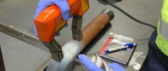
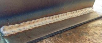
- Surface preparation consists of cleaning the seam and heat-affected zone from scale, traces of rust, dirt, and traces of lubricants. To ensure clarity of the control pattern, dark metals are coated with white water-based paint, and the layer is made thin.
- To carry out magnetic powder flaw detection, the workpieces are magnetized (methods are listed in a separate section). The sensitivity of testing depends on magnetization in flaw detection.
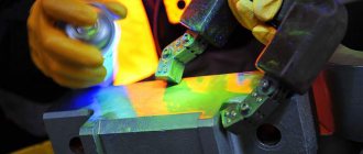
- An indicator with ferromagnetic particles is applied in a way that depends on the type of flaw detection devices.
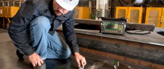
- Inspection of the controlled area, if necessary, is carried out using optics and devices required by regulations.
- Interpretation of the indicator pattern obtained during magnetic particle flaw detection is carried out with the fixation of defects after the unchanged position of the indicator particles. The inspector deciphers the drawing, comparing it with photographs from the atlas of defects. The data is entered into a log.
- Demagnetization is the final operation. The parts are exposed to a magnetic field with a damped amplitude or heated to the Curie point. Demagnetization control is mandatory during flaw detection.
- Remains of the magnetic particle indicator are removed manually or using wiping compounds.
Types of magnetic non-destructive testing and their implementation technologies
The key reason for using various magnetic inspection methods is the integrity of the products being tested. To control the quality of welding joints, magnetic particle and magnetographic methods are used, and the induction method is less commonly used.
Magnetic particle flaw detection
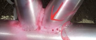
Quality control of defects using the magnetic particle method is based on detecting a local zone of magnetic leakage flux above the surface of the defect using ferromagnetic powder. It is possible to use the powder in dry or liquid form , as part of an aqueous or oil magnetic suspension. Powder with magnetic particles is applied to the welding joint area. Next, a nonlinear field force (ponderomotive) begins to influence these powder particles, which tends to attract ferromagnetic particles to the region of highest concentration of magnetic field lines. As a result, iron-containing particles form a peculiar pattern on the surface of the internal defect. This control can only be carried out on smooth, even and clean metal surfaces.
Options for using ferromagnetic powder:
- A ferromagnetic composition is applied to the weld area with a special sprayer..
- The part to be welded is completely lowered into a container with powder.
Both options are valid for both dry and liquid types of powder. This technique can be used to test welds with a ferromagnetic composition that have relative magnetic permeability.
Welding defects that can be detected using the magnetic particle method:
- superficial , with a width of 0.002 mm and a depth of 0.01 mm or more;
- subsurface , located up to 2 mm depth;
- internal , depth more than 2 mm (for delaminations or large cracks);
- defects under a non-magnetic coating , taking into account that the thickness of the coating is no more than 0.25 mm.
Necessary equipment:
- Magnetizing device.
- Ferromagnetic powder or magnetic powder suspension.
- Spray.
- Flaw detector.
- Test samples with defects.
- Degaussing installation.
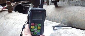
Approximate cost of a magnetic flaw detector on Yandex.market
It should be noted that to search for subsurface defects, using dry powder allows you to achieve better results compared to the “wet” form. This is due to its higher degree of sensitivity. To assess the sensitivity of the powder itself, control samples of parts with varying degrees of defects are used.
Magnetographic method of searching for defects
The magnetographic method for monitoring welding operations is based on searching for the magnetic stray field that occurs in the defect area when the part is magnetized. Due to the formed cracks or cavities, the scattering location remains fixed, like an imprint of magnetic disturbances on the elastic tape of the flaw detector. The flaw detector must be in close contact with the welding joint. On the magnetic tape, the particles of ferromagnetic powder remain motionless, thus indicating the localization zone of interaction of a magnetic nature with a defective field.
The magnetographic method is used to control welding seams with a thickness of up to 12 mm. This method can detect so-called macrocracks, gas porosity, slag inclusions, and welding imperfections.
Sequence of control actions:
- Preparing the surface of the part for inspection (removing slag, splashes, dirt).
- Close application of flaw detector tape to the welding joint.
- Magnetization of metal , according to the thickness of the weld and its properties.
- Interpretation and evaluation of the results obtained using the flaw detector reading device.
- Demagnetization of the part being tested.
The flaw detectors are adjusted using reference tapes fixed on test samples of welds. The location of the defect and its internal depth are determined on the indicator screen. The shape of the resulting pattern will correspond to the area where the defect is localized; the depth of the crack is indicated by the saturation of blackening on the screen.
The magnetographic method is best used to detect planar type defects, such as cracks, lack of fusion of metals, and welding imperfections with a maximum depth of up to 20-25 mm.
Necessary equipment:
- magnetizing device;
- flaw detectors for working with ferromagnetic tape;
- portable power station;
- magnetic tape on triacetate or mylar base;
- control samples of welding seams;
- degaussing technology.
Methods of applying the indicator
For magnetic powder testing, dry, wet, and paste-like indicators are used. Dry is a mixture of fine metal filings; it is applied to the surface in its natural state, without adding liquids.
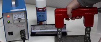
The dry flaw detection method is effective for detecting discontinuities, slag inclusions on the surface or subsurface type defects. For the manufacture of magnetic particle indicators, iron scale, babbitt, magnetite, and other highly magnetizable materials are used. The field in the welded workpiece is created by a U-shaped electromagnet connected to a source of direct or alternating current with a power of 300 to 600 amperes. The ferromagnetic mixture is applied from an aerosol package, dispersed by a sieve, and directed by a bulb.
In wet indicators, magnetizable particles are suspended. They are added:
- in water with anti-corrosion substances;
- liquid soap solution;
- kerosene;
- transformer oil;
- special concentrate based on polymers.
For flaw detection, compounds are applied using several methods:
- using a brush;
- immersing in suspension;
- pouring liquid over the surface being examined.
The wet flaw detection method is used to identify surface discontinuities in welds.
Magnetic particle flaw detection
Magnetic particle flaw detection is based on examining the magnetic resistance of a weld or metal of a solid part. Ultra-sensitive photographic paper is applied to the part, onto which an even thin layer of powder is poured and placed in the field of a strong direct current solenoid, the powder is sprayed with a quick-drying transparent varnish (zaponlak, etc.), then the paper is illuminated with strong light and developed. A picture of the magnetic field is created on paper, which determines the presence or absence of defects.
| Magnetization of a sample with a defect in a uniform longitudinal field.| The influence of magnetic powder dispersion on the detection of defects. |
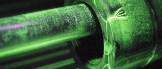
Magnetic particle flaw detection reveals surface and subsurface defects such as discontinuities. Magnetic particle testing is used only for ferromagnetic materials that are subject to magnetization. When a product (Fig. 3.35) with a defect is placed in a longitudinal uniform magnetic field at the location of the subsurface hidden defect, the magnetic flux will dissipate into space, which creates magnetic poles on the surface of the product.
Magnetic particle flaw detection allows you to detect surface and subsurface (at a depth of 1 - 2 mm) defects in welded joints such as cracks, lack of fusion, pores, undercuts.
| Magnetization of a sample with a defect in a uniform longitudinal field.| The influence of magnetic powder dispersion on the detection of defects. |
Magnetic particle flaw detection is carried out only in semi-automatic mode. The processes of magnetization and demagnetization of products are subject to automation. The capabilities of magnetic particle flaw detection are largely limited by the quality of the magnetic powder used and the size of its grains. The graphs (Fig. 3.36) show the relationship between the size of the powder grains and the degree of detection of various de-sects. The magnetic properties of the powder affect the quality of control in the process.
| Scheme of ultrasonic testing of rivets. |
Magnetic particle flaw detection of riveted drums is carried out to identify surface defects on shells, bottoms, pipe and rivet holes. To control the metal of shells and drum bottoms, current-carrying electrodes are installed at a distance of 180 - 200 mm.
| Scheme of cutting samples to control the mechanical properties of the drum metal. |
At the end of magnetic particle flaw detection, possible burns of metal at the contact points of the current-carrying electrodes are removed with an abrasive tool. Defective areas can be selected with a grinder and re-inspected by magnetic particle inspection or etching.
In the practice of magnetic particle flaw detection, magnetizing devices in the form of portable alternating current electromagnets, characterized by their simple design, have proven themselves well. These devices are recommended for use when inspecting products with a wall thickness of more than 20 mm. The magnetic core is assembled from plates of electrical iron with a thickness of 0 2 - 0 6 mm. Power is supplied from an AC mains voltage of 12 V. The electromagnet must have pole pieces of various shapes to ensure reliable contact during local magnetization of a part or assembly.
| Drum metal magnetization scheme for detecting axial cracks in the walls of pipe holes and fittings. |
The surface to be subjected to magnetic particle flaw detection must be cleaned to a metallic shine. When conducting operational inspection, good results are obtained when inspecting an uncleaned surface covered with a thin layer of nitro enamel.
| Kinetic diagram of a semi-automatic control and sorting machine. |
In the case of magnetic particle flaw detection, c. is usually used. With this, magnetization is carried out either by passing an electric current through the product (or a nearby conductor), or by introducing the product into an external magnetic field created by a coil with different cores. There are a number of machines used for magnetization purposes.
Types of magnetization
With the magnetic particle testing method, types of magnetization that are applicable to parts of simple shape are more often used:
- circular creates a uniform magnetic field inside the part, there are no magnetic poles at the ends;
- longitudinal is called pole: a plus is formed at one end of the workpiece, a minus at the other, the field is directed along the part;
- combined involves the simultaneous influence of several multidirectional magnetic fields (in two mutually perpendicular directions, three or more).
In production, a type of magnetization of welds in a rotating magnetic field is used.
Various types of electric currents are used for magnetization:
- constant creates uniform induction;
- variable is applicable for less sensitive control methods;
- Pulse characteristics are close to constant.
Single-cycle and rectified current generators are built into flaw detection devices.
The legislative framework
Basic documents regulating the conduct of MTD
| Name | Description |
| GOST R 56512-2015 | Non-destructive testing. Magnetic particle method. Typical technological processes |
| GOST R ISO 9934-1-2011 | Non-destructive testing. Magnetic particle method. Part 1 |
| GOST R ISO 9934-2-2011 | Non-destructive testing. Magnetic particle method. Part 2. |
| GOST R 53700-2009 (ISO 9934-3:2002) | Non-destructive testing. Magnetic particle method. Part 3 |
| GOST R 55612-2013 | Non-destructive magnetic testing. Terms and Definitions |
Why is it worth ordering magnetic particle testing from REP LLC?
- certified laboratory and personnel . Our specialists are certified in accordance with PB 03-440-02 and ISO 9712 for magnetic and other testing methods. This allows us to work with all objects specified in the list of control objects approved by Rostechnadzor. We also work with objects of the Russian Maritime Register of Shipping.
- full-fledged material and technical base . We use equipment and consumables from world brands.
- versatility _ We use a magnetizing device with permanent magnets, which allows us to work in places where there is no current source. Our team includes industrial climbers, thanks to which we work at heights.
Want to order but still have questions?
Check the condition of pipelines or metal structures in production with a minimum of investment - call or contact us via the feedback form. We will advise you!
Sensitivity of magnetic particle flaw detection
Flaw detection is carried out on materials with a relative magnetic permeability of at least 40, the sensitivity of the MTD depends on:
- on the electromagnetic properties of the material used for research (mobility of indicator particles);
- magnetic characteristics of workpieces (ability to be magnetized);
- type of current, at constant a stable magnetic field is formed
- smoothness of the surface of the part, roughness is graded from 2.5 to 40 microns, the lower the roughness, the more accurate the control;
- magnetizing field strength;
- the position of discontinuities and other defects relative to the induction lines;
- method of applying an indicator to the surface of a part;
- testing conditions (the “dry” method of testing welded joints has higher accuracy);
- method of registering an indicator pattern over defects.
Magnetic particle method
The magnetic particle testing method involves applying ferromagnetic powder to the surface of a magnetized welded joint in the form of a suspension also containing kerosene, oil and soap solution (“wet” method), or in the form of an aerosol (“dry” method). Under the influence of the retracting force of magnetic stray fields, powder particles move along the joint surface and accumulate in the form of rollers over defects. The shape of these clusters corresponds to the outlines of the detected defects.
Control technique. The magnetic particle testing method includes the following operations (GOST 21105 - 85):
- preparing surfaces for testing;
- preparation of the suspension, which consists of intensive mixing of the magnetic powder with the transport liquid;
- magnetization of a controlled welded joint;
- applying powder to the surface of the controlled connection;
- inspection of the surface of the controlled connection and identification of areas covered with powder;
- demagnetization of the connection.
This method is characterized by high sensitivity to thin and small cracks, ease of implementation, efficiency and clarity of results. It is widely used for monitoring longitudinal welds of structures made of magnetic materials, and in particular for identifying cracks and narrow (tight) lack of fusion in butt welds of pipelines produced by arc methods. To increase the sensitivity of testing, it is advisable to remove part of the weld protruding above the front surface of the joint before testing.
Sensitivity of the method. The sensitivity of this method depends on a number of factors: the particle size of the ferromagnetic powder and the method of its application (“dry” or “wet”), the strength of the applied magnetizing field, the type of current (alternating or direct), the shape, size and depth of defects, their orientation relative to the surface of the welded joint and the direction of magnetization, the state and shape of the surface, as well as the method of magnetization.
Ferromagnetic powder must have particles with a size of 5 ... 10 microns. To identify deep defects, larger magnetic powder is used. To prepare magnetic suspensions, magnetic powder with small particles is used. In addition, to achieve maximum mobility, the magnetic powder particles must have the correct shape. Particles acquire additional mobility if they are coated with a pigment coating with a low coefficient of friction.
The type of magnetizing current and the method of applying ferromagnetic powder do not significantly affect the detection of surface defects, but at the same time they significantly affect the diagnosis of subsurface defects. The advantage of using direct current in this method is due to the fact that it creates a magnetic field that penetrates deeply into the metal. However, welded joints made of metal 20 mm thick should not be magnetized with direct current, since they cannot be demagnetized after testing.
When using alternating current for magnetization, under the influence of the skin effect, the current and magnetic flux densities at the surface of the welded joint increase, which contributes to better detection of only surface defects.
The advantage of using the “dry” deposition method for detecting subsurface defects is explained by the fact that a greater magnetic flux force is required to move a ferromagnetic particle in a viscous suspension than to move the same particle in air.
With increasing strength of the applied magnetizing field (until saturation induction is achieved), the sensitivity of this control method increases.
When testing by magnetic methods, planar defects (cracks, lack of penetration and lack of fusion) oriented at an angle of 20 ... 90° to the direction of the magnetic flux are most confidently identified. Round defects (pores, slag inclusions and cavities) cannot create sufficient leakage flux
and, as a rule, are poorly detected during magnetic testing. Practice has established that the magnetic particle method detects surface and subsurface (at a depth of no more than 2 mm) cracks with a width of more than 1 micron, a depth of more than 50 microns and a length of at least 0.5 mm.
It is also possible to detect relatively large defects (lack of penetration, pores, slag inclusions, etc.) with a cross-sectional area of more than 2 mm2, located at a depth of 5 ... 6 mm from the surface of the weld. As the depth of defects increases, the rate of formation of magnetic powder accumulations decreases, which makes them difficult to detect and determine their type.
The sensitivity of the control largely depends on the quality of the surface on which the suspension or powder is applied. The optimal surface roughness of welded joints subjected to magnetic particle testing corresponds to the Ra parameter of 2.5 ... 1.25 μm. On such a surface the highest sensitivity of the method is ensured. An increase in surface roughness leads to a decrease in control sensitivity. So, if after processing the surface of the test joint acquires a roughness of Ra 3.2 ... 2.5 μm, then testing in those modes that ensure the detection of thin defects (1 μm thick) is difficult due to the appearance of a background from magnetic powder, which requires a decrease in the magnetizing field strength , and therefore reduces the sensitivity of control.
Polished surfaces (with a roughness Ra of 0.32 µm or more) due to the presence of glare on them are difficult to inspect and reject, especially under direct illumination with incandescent lamps. It is advisable to carry out a control inspection of polished surfaces in diffused light or after covering them with a very thin (no more than 15 microns thick) layer of paint that removes shine, for example nitro enamel NTs-25.
If there are sharp transitions (for example, undercuts) or microroughnesses on the surface of the controlled welded joint, then ferromagnetic powder accumulates not above the defects, but in areas containing such transitions and depressions. Consequently, in this case it is impossible to unambiguously judge the presence of internal defects.
Magnetization methods. Magnetic testing is performed either in an applied magnetic field or with residual magnetization. The first method is used to detect subsurface defects located at a depth of more than
10 microns, and also when the welded joint is made of a soft magnetic material (for example, steel) or has a complex shape and the power of the flaw detector does not allow magnetizing the entire joint due to its large size. At the same time, control in an applied magnetic field does not always have higher sensitivity than control with residual magnetization.
If the control is carried out with residual magnetization, then the connection is pre-magnetized, and after removing the magnetic field, a ferromagnetic suspension or powder is applied to its surface. Since such testing is possible only with a fairly high residual magnetization, it is used to test connections made of hard magnetic materials with a coercive force Hc > 800 A/m. A connection made from a material with Hc < 800 A/m cannot be checked with residual magnetization, since a weak magnetic field is formed above the defect. This method has the following advantages: it allows you to install the connection in any required position to ensure good illumination of the surface and the possibility of inspecting it with the naked eye, as well as to reduce the likelihood of burning sheet parts and contact with the heads of the flaw detector, since for residual magnetization, current is passed through the connection for a short time ( for 0.1 ... 0.5 s) with breaks between switching on for 1 ... 2 s.
In the practice of magnetic testing, the following methods of magnetization of welded joints are used: combined, circular and pole. Combined magnetization is carried out only in an applied magnetic field, and circular and pole magnetization is carried out both in an applied magnetic field and with residual magnetization.
With combined magnetization, two (or more) magnetic fields are used simultaneously. For example, magnetization of a pipe is accomplished by using a solenoid and passing current through a conductor running inside the pipe. Two magnetizing fields are added in such a way that the lines of force of the resulting magnetic field have the shape of a spiral. The resulting field passes through all parts of the object at different angles, which increases the detection of defects oriented in different directions.
Circular magnetization is used to detect longitudinal defects (cracks, lack of fusion or elongated slag inclusions). This magnetization is performed by
passing current through a controlled part or through a conductor placed in a hole in this part. Circular magnetization is most effective when testing cylindrical parts. The current strength, A, passed through a cylindrical part to magnetize it is calculated using the formula
Ic = πDH,
where D is the diameter of the part, cm; H—magnetic field strength, A/cm.
When choosing the value of H, the following must be taken into account: if point P′ of initial magnetization (Fig. 34) turns out to be to the right of point P of maximum relative magnetic permeability, a decrease in the cross-sectional area of the metal due to the presence of a defect will cause an increase in magnetic induction, and can also lead to an increase in magnetic permeability and , as a consequence, to a decrease in the leakage flux. As a result, the defect may not be detected.
The best conditions for detecting defects are created in the region of decline of the curve μ = f(H) (point P′). At high field strengths H, the difference between the scattering fluxes above defects and in the environment decreases, which makes it difficult to identify defects. To be able to detect the majority of surface defects in welded joints made of structural steels, the optimal magnetic field strength on the surface of the joint, if the control is carried out with residual magnetization, should be 80 ... 160 A/cm.
Rice. 34. Dependences of magnetic induction B and relative magnetic permeability μ on magnetic field strength H for ferromagnetic material : P, P' - points corresponding to the initial magnetization of the metal and the region of best detection of defects
The current strength, A, required for circular magnetization of the plate is determined by the formula
Iп = 2(b + S)/H,
where b and S are the width and thickness of the plate, respectively.
Pole magnetization is divided into longitudinal, transverse and normal. With longitudinal magnetization, the direction of the magnetizing field coincides with the direction of the axis of the weld. Longitudinal magnetization, carried out using electromagnets, permanent magnets or solenoids, is used to identify transverse defects located at an angle of at least 20° to the longitudinal axis of the weld. With transverse magnetization, the direction of the magnetic field intensity vector is perpendicular to the longitudinal axis of the weld. Normal magnetization is a special case of longitudinal and transverse magnetization.
The sensitivity of the magnetic control method, carried out with longitudinal residual magnetization, significantly depends on the speed of removal of the magnetizing field. With a rapid decrease in field strength, defects are detected reliably, and with a slow weakening of the field with the same initial strength, defects are not detected or are detected weakly, i.e., the duration of the decrease in current strength from the maximum value to zero should not exceed 5 μs.
Equipment and materials. Flaw detectors designed to implement the magnetic particle testing method include a current source, a device for supplying current to the part, a pole magnetization unit (solenoids, electromagnets), a device for applying powder or suspension to the controlled welded joint, and a current (or field strength) meter. In flaw detectors, they most often use a circular magnetization method, passing alternating current through the part (or through a rod), and longitudinal magnetization with direct current. For magnetic particle testing, three types of flaw detectors are usually used: stationary universal and specialized - mobile and portable.
Stationary universal flaw detectors are widely used in large-scale production of various types of parts. With their help, you can control parts (or batches of parts) of various configurations with a productivity of tens to hundreds of pieces per hour.
In stationary universal flaw detectors, magnetization can be carried out by all known methods (longitudinal, circular, combined). Several models of stationary flaw detectors are successfully used: UMDE-2500, KhMD-10P, MD-5 and others, which differ from each other in the type of magnetizing current and power and are intended for testing parts of different sizes.
The PMD-70 and MD-50P models of specialized mobile and portable flaw detectors are commercially produced. The portable magnetic flaw detector PMD-70 is used to control welds in the field. It implements pole longitudinal and circular magnetization methods. The MD-50P mobile flaw detector is designed for inspection of large, massive structures, performed in parts.
The material used for the preparation of ferromagnetic powders is mainly finely ground iron oxides (with a particle size of 5 ... 20 microns), sometimes pure iron scale obtained during forging and rolling, as well as steel filings formed during grinding of steel products. To better identify structural defects, colored ferromagnetic powders (red, silver, etc.) are used, obtained by coloring dark powders or annealing them using a special technology.
To prepare magnetic suspensions, oil-kerosene mixtures (with a 1:1 ratio of oil and kerosene) are most often used, per 1 liter of which there are 50 ... 60 g of ferromagnetic powder. Aqueous suspensions can also be used, for example, soap-water, in which per 1 liter of water there are 5 ... 6 g of soap, 1 g of liquid glass and 25 ... 30 g of magnetic powder.