We will learn how to control welded joints on a pipeline in this article. To get an idea of the real state of the metal at the joints, so-called non-destructive testing of pipeline welded joints is used. Safety along with the reliability of the structure is often determined by the quality of the seams.
Standards in legislation create strict guidelines for the process. It is carried out only by professionals with the appropriate skills.
Methods of quality control
Given the importance of reliable connection of welds, quality control of welded joints must be carried out systematically. This is an important technological process that involves searching for damage that could cause further destruction of the pipeline and disruption of the system as a whole.
The process includes systematic operational control, mechanical testing of pipeline fragments with welded joints. The continuity parameter of the joint is also checked over the entire thickness of the metal, because the weld location must be one piece of alloy without thinning, but sagging is allowed.
Pneumatic and hydraulic tests are carried out using special stands. All classical methods for quality control of pipe welds are given in GOST 3242-79.
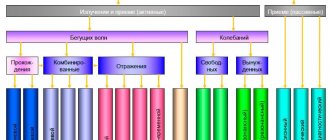
In addition to destructive methods, non-destructive methods are also used:
- magnetographic control;
- inspection of welded joints by X-ray radiation;
- control of welded joints by gamma radiation;
- ultrasonic flaw detection of connections.
Let's consider each method separately, because they all have their own characteristics, which in one way or another affect the process of determining the state of the welded joint. In this case, the entire perimeter of the joint is checked to ensure compliance with the thickness throughout the entire joint structure. Depending on the load, pipelines are usually divided into 4 categories.
Weld undercut
Pipelines: analysis of various defects
A defect in a welded joint in the form of a bead appears when the melt flows strongly onto the cold weld zone. The beads may take the form of individual drops, or they may extend over a considerable distance along the weld seam. Causes of influxes:
- excess welding current;
- incorrect tilt;
- movement of the electrode during welding;
- failure to take into account the angle of inclination of pipes when connecting them.
Sagging is often accompanied by the appearance of uneven and poor-quality penetration of the weld metal, as well as the occurrence of external and internal cracks.
Surge formation patterns.
Undercuts are grooves in the metal that appear at the border with the weld. Such a defect reduces the actual cross-section of the weld and leads to the appearance of excess stresses, which can lead to their growth into cracks with subsequent destruction of the welded joint.
Defects in the form of burns appear as holes through which the melt from the weld pool has flowed. The reason for the formation of such a defect can be a low welding speed, an excessive gap between the ends of the pipes during welding, or an excess of the welding current. Insufficient or uneven penetration of seams is caused by the lack of reliable connection of edges in small areas. Such a defect reduces the actual cross-section of the weld and leads to the appearance of residual stresses, which can cause subsequent cracking and destruction of the metal.
Cracks can be considered the most dangerous types of defects. They can appear at any point in the welding zone (including the seam area of the metal) and have any direction (longitudinal and transverse). Based on their size, they are divided into microcracks and cracks. Such a defect is caused by both incorrect crystallization conditions of the melt and excess concentrations of carbon, sulfur and phosphorus in the weld pool. Cracks noticeably affect all the main parameters of pipeline welded joints.
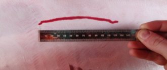
Table of permissible undercut values during welding.
Foreign inclusions weaken the strength characteristics. The most dangerous is the presence of slag inclusions formed when the surface of the welds is insufficiently cleaned of slag after welding. These inclusions significantly accelerate metal corrosion.
Gas or air voids usually form within the weld. They can be single in nature, or they can appear in groups and even form chains of voids. Pores can be located on the surface of the metal, forming depressions (fistulas). Pores significantly reduce the strength of seams, and the formation of chains of voids can cause depressurization of the pipeline.
Disturbances in the structure of the weld metal or weld zone can manifest themselves through an increase in the concentration of oxides, micropores and microcracks, and coarse grain size. The thermal regime plays a decisive role in the formation of the metal structure. Excessive heating leads to the formation of large grains in the structure. When the metal is burned, grains with oxidized surfaces may appear. All this leads to the fragility of the metal.
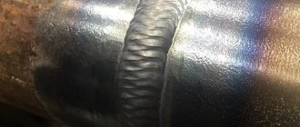
Requirements for welds
Any welds in the pipeline must not have cracks, craters, burns or other defects of poor quality welding. Undercuts with a depth of more than 0.5 mm will also be very critical. This requirement is especially important for pipelines that operate under pressure from 10 MPa.
The quality of welded joints of different thicknesses of metals is carried out using our own method. For example, when the steel thickness is 16 mm or more, the radiographic method is used. And connections from steels ХМ, С and ХГ are made using the ultrasonic method, during which final flaw detection is carried out.
It is important to follow the sequence of quality control of welded joints. For example, before performing radiography or applying the same ultrasonic flaw detection, it is necessary to use a magnetic particle or color method. This requirement applies to areas near the seam at a distance of 20 mm.
Magnetographic control
1 - ferromagnetic film;
2 - electromagnet; 3 - direct current source; 4 - crack in welding; pulses: 5 - cracks, 6 - lack of penetration, 7 - networks of pores Magnetographic testing is nothing more than magnetic flaw detection. This method allows you to detect the so-called stray fields. They are detected when defective areas are magnetized and are reflected on the radiogram in the form of graphs.
If the seam is made with high quality and the metal is fused evenly throughout its thickness, then the magnetic lines are distributed evenly in it without bending. If there are various defects in the seam, they will spread chaotically. The field is deflected and as a result of this, so-called stray fields are formed.
This method is used when performing quality control of semi-automatic welding in a submerged arc or in an inert environment. The metal thickness should be in the range from 2 to 25 mm. The magnetographic method allows you to identify the following defects:
- longitudinal microcracks;
- lack of penetration;
- chains and accumulations of slag;
- gas pores.
All of the above has a significant impact on the strength of the connection and can cause fatal failure. The control procedure using magnetography is carried out in two stages:
First, the product is magnetized with a special device. At this stage, the magnetization fields are recorded on magnetic tape.
At the second stage, information is read from the tape. For this purpose, flaw detectors are used.
Ultrasonic flaw detector Smartor
To perform magnetization, movable and stationary magnetizing devices are used. Stationary ones affect the seam from both sides, outside and inside. Movable magnetizers of the PNU type are most often used. In the process of working, they create a homogeneous flow enclosed between two poles.
The poles are connected by a core to create a half circuit of magnetic flux. The second part of the core is the weld. A magnetizing coil is placed on the core. The magnetization apparatus moves on special non-magnetic wheels. The distance between the controlled joint surface and the poles plays an important role.
Movable magnetizing devices are used to control welded joints of small and medium-sized pipes with a diameter of 100 to 1020 mm. The wall thickness should not be more than 16 mm. If it is necessary to control the quality of a welded joint on a smaller pipe, then magnetizing pliers or forks should be used.
To carry out quality control of the welded joint of pipes of larger diameter in the range from 1220 to 1420 mm, a device that has stepwise movement is used. This device is called MUN-1. It allows you to control joints made of metal up to 20 mm thick. It is equipped with a remote control, thanks to which the process is controlled and the device is controlled. To control the quality of joints of different diameters in this range, special replaceable shoes are used.
To carry out quality checks, construction organizations contact the construction control center
If you need to check the connection of pipes with a diameter of 1420 mm and a wall up to 25 mm, then you must use a UMD-142 type installation. It is mounted on special mechanized welding bases. If it is necessary to carry out quality control of welding of pipeline joints on the route, then the LPM-K mobile laboratory is used for these purposes. A ring magnet is used as a magnetizing device. It allows you to completely cover the entire joint surface.
The operation of the magnetizing device used in the inspection of large pipe joints requires a powerful power source. Mobile stations of the SPP-1 and SPA-1 types are used. It is also possible to use welding machines, but in this case it is necessary to use a rheostat. To record data, previously a tape 35-70 mm wide on a triacetate or lavsan base of types MK-1 and MK-2 was used. It was stretched by motors over the magnetized area. The device had a beam tube on which single magnetization pulses were reflected.
MD-30G, MD-11G, MGK-1 and MDU-2U were used as means of visual display of information.
Flaw detection of welded pipe joints on gas and oil pipelines
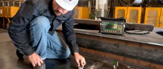
External visual inspection
The first method of non-destructive testing of pipeline welded joints is external visual inspection and measurement, which is carried out continuously at all stages of pipeline manufacturing and operation. First of all, by visual inspection of the welded pipe joint, the presence of external defects is determined, such as sagging, undercuts, pore craters, burns, external cracks and others. For such an examination, it is recommended to use a magnifying glass with tenfold magnification.
A generalized scheme for justifying the standards for the admissibility of defects.
The next step is to measure the dimensions of the welded elements and record the location of defects. When taking measurements, the following dimensions of the weld are established: its width and height, the size of the convex sections and the angles at the border with the seam zone. Special templates are used to control dimensions. The results of weld measurements are compared with the standardized values established by state standards for these types of welding work.
X-ray inspection of welded joints
One of the most common methods for quality control of welded joints today is X-ray radiation. It is also called x-ray and gammagraphy. The peculiarity of this method is that gamma rays are able to pass through the welded joint. To record the results, a special radiographic film is used. As a result of the action of gamma rays, a pattern appears on the film that is hidden from normal vision. It can only be seen after development and curing, as is the case with photo processing. In order to better reveal defects, concentrators made of metal or fluorescent screens are used.
It is known that X-rays are the same electromagnetic vibrations that have a certain frequency. A special X-ray tube receives radiation. It is equipped with two electrodes located in a cylinder. The process of radiation formation occurs at the moment of deceleration of electrons, which are retained by the anode. In this case, the electron receives kinetic energy equal to E=eU. When the minimum wavelength is reached Emax=hc/λ0.
electrons at the anode, the maximum amount of X-ray radiation is generated. Considering that h is Planck’s constant and equal to 6.625∙10-34 J/s, c is the speed of light in vacuum, and e is the electron charge equal to 1.602∙10-19 C, then by equating E and Emax, we can determine the minimum wavelength λ0 and it will be equal
hc/(eU) = 1.24∙10-6/U
If you increase the voltage at the anode, the wavelength becomes shorter. As a result, the spectral composition of X-rays is emitted. As a result, the maximum energy of the continuous spectrum increases. If you change the current of the anode tube, then the intensity of the X-ray radiation changes similarly. The radiation dose can be determined from the product of the anode current and the duration of time during which the exposure occurred.
An X-ray tube has a very low efficiency, which does not exceed 2% of the total electron energy. Everything else is spent on heating, which is carried out by a special medium. To record X-ray radiation passing through a welded joint, an emulsion of a special radiographic film is used.
1. Radiographic technical film R8F; 2. X-ray film Agfa D5
Since any radiographic film used for welding quality control does not have an ideal section on the curve, the contrast and gradient are determined individually from the relationship γd = dD/(d log D). D – Film blackening density. If screenless film is used, then the density of blackening in them Db is determined by the proportionality of the developed spots. Exposure X is determined by the number of quanta that passed through the film. In this case, Db = Dmax[l-exp(-kX], k is the film sensitivity, and Dmax is the value of the maximum blackening density. If a screen is used, then the equation will look like:
De=Dmax[1-1/(1+kX2).
Films have so-called spectral sensitivity. This property indicates the ability to obtain different densities of blackening with the same exposure but different dose. Spectral sensitivity is designated by the letter Q and is determined by the formula
Q=1/X
All radiographic films are characterized by their resolution. It determines the number of distinguishable dashed lines at a distance of 1 mm. The highest quality films in this regard are films of the RT-4 M and RT-5 types. They are also fine-grained. Control using intensifying taps allows you to get a more significant picture, but it is important to choose the right material for making the screen, which can be tin, lead, or tungsten. The material is selected depending on the supply voltage up to 100 kV and above 100 kV.
On an industrial scale, RT-SSh film is used to control the quality of the weld. The screen used is lavsan coated with heavy elements that replace lead. There are 4 classes of radiographic images.
Inspection of welded joints of pipelines using gamma radiation
Gamma flaw detectors SENTINEL 880 series
The process of quality control of welded joints on pipes is an important step when laying communications using steel pipes. Basically, the welding method is used, since it allows one to achieve the highest levels of tightness, and, accordingly, reliability of equipment operation. To determine the quality of welding, different methods are used, and each has its own characteristics, since it allows one to determine hidden defects in metal of any thickness.
There are destructive and non-destructive technologies that allow you to obtain different data. One such method is the process of gamma radiation irradiation. This is nothing more than a beam of energy that is formed during the decay of nuclei in various substances. Moreover, both natural and artificially produced components are used. To obtain such radiation, an appropriate source is required. These are the radioactive isotopes of thulium 170, indium 192 and cesium 137. The isotopes of strontium 90, europium 152 and 155 and selenium 75 are also often used.
The peculiarity of the process of nuclear decay is an unregulated process, but the reaction is static. To obtain the desired result, it is necessary to regulate the intensity of decay, thereby changing the amount of radioactive substances that reacted. The exponential law is at work here. The formula for the dependence of decay activity is as follows:
Q(t)=Q-0e-0.693t/T.
To determine the activity of radioactive substances, the concept of half-life was introduced. It characterizes the time during which exactly half of all existing nuclei decay in a medium with certain parameters. Accordingly, each substance has its own specific period. In this case, the degree of activity of substances is determined from the number of free atoms that can enter into a half-life reaction. This quantity is also called the decay rate, which indicates the overall outcome of the reaction.
The exponential dose of gamma and x-ray radiation is characterized by the presence of quantum radiation energy. It is converted into kinetic energy, which is transmitted to charged particles that are in the atmospheric air. The exposure dose rate is determined from the dose that was absorbed per unit of time.
The unit of measurement for this characteristic is amperes per kilogram. The ratio of roentgens per second is also used for calculations. The power is determined by the product of the power of gamma radiation without an absorber and the ratio of the dose factor of the accumulator to the force. In this case, the exponential is taken to the power of the product of the relative reduction coefficient and the absorber area. The formula for calculating this characteristic is as follows:
P=P0e-µδB/F2.
The following symbols are used in this formula:
- P0 – exposure dose rate without absorber;
- µ—radiation intensity reduction factor;
- B – dose accumulation factor.
The ionizing effect is compared by the gamma equivalent of the drug, which arise as a result of ionization. Radium radiation is the reference because it meets the basic laws. As a result of experimental tests, it was proven that 1 g of radium is capable of creating an exposure dose of up to 2.13x10⁻³ C/kg.
In this case, a platinum filter is necessarily used, the thickness of which is at least 0.5 mm, and the distance at which the measurement takes place is 1 cm. The exposure dose created by one gram of radium is called a gram equivalent. In this case, the radiation intensity is the ratio of the flux of radiation quanta to the time during which the irradiation occurred.
Features of quality control of welds using gamma radiation
To perform weld analysis in pipes, special portable devices called gamma flaw detectors are used. They use special protective radiation heads. Their presence is mandatory, since during the operation of the emitter, a dangerous one is created, which can lead to health problems.
Welding quality control is carried out by opening the head shutter to a small angle. The created beam of radiation should be sufficient to illuminate the metal through. Such devices are called hose-type flaw detectors.
Gammarid 192-120, 170-400 - characteristics
The so-called gammarid-23 is also used. This device has the ability to operate from multiple radiation sources based on cesium 137 and iridium 192. The weld is processed from a conical tip emitted from a closed container. The device is equipped with flaw detectors Gammarid-20, Gammaridd-25, Gammarid-25M, etc. It is also possible to check the quality of pipeline welded joints on the route; for this, mobile devices “Magistral” and “Magistral-1” are used. Using such devices, you can examine pipes with a diameter of 1420 mm, and the metal thickness can be as much as 40 mm.
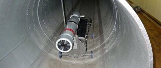
The peculiarity of such devices is that they can be used not only outside, but also inside the pipeline, thereby allowing one to analyze the quality of the connection from the reverse side. In this case, the active device can be immersed in the pipe at a distance of up to 1.5 km. This equipment only works in conjunction with the AKP-141 system.
Other equipment for monitoring using gamma radiation
The Parus-3M installation is also used to control the quality of welds on pipes. They move the emitter at a speed of 15 m per minute due to the built-in motor.
In this case, any option can be used as an emitter. To get a more complete picture of the seam, the recorder moves in a circle. On the routes, the quality of pipe welding is checked by mobile laboratories such as RML-2V and VLK-2.
What happens?
Formula for relative sensitivity Wrel
During quality control, the sensitivity Wrel is of no small importance. It is determined by the picture that was formed during the analysis process. Groove standards are used to identify defects. Using it, you can determine sensitivity using the formula:
Wrel=2.3ΔDminB'/γDµδ(1+u/Δb)100%.
This formula takes into account all sorts of factors that can affect the progress of quality control of a welded joint. A factor in the presence of defects is general blurriness. It usually indicates the presence of step transitions. In this case, the blurring of scattering is determined by the formula: uр=uВgб. Where uB is the internal blur. and the total is determined by the formula
u=3√(u3Г+ u3V)
To check the quality of the weld of thick-walled pipes, it is necessary to substitute uP in the formula instead of uB. The resulting image contrast is a factor in the presence of defects. It can be determined by calculation using the formula:
SI=(LD-Lb)/Lbx(1+u/Δb)x100%
When carrying out practical measurements, the relative sensitivity is determined by the form:
WOTH=h/(δ1+δ2)х100%
The equation uses the following notation:
- h – minimum depth of the flaw detector groove;
- δ1 – indicator of the thickness of the base metal;
- δ2 – standard size.
The parameters of the welded joint are measured externally. The source is mounted on the surface, and on the back side there is also a tape on the outside on which the readings will be recorded. In this way, it is possible to X-ray pipes with a size of less than 400 mm and at a distance from the seam of up to 20 mm.
Quality control of welds using ultrasonic flaw detection
Magnetic flux lines passing through a weld
Ultrasonic flaw detection is used to control the quality of welded joints with a pipe wall thickness of 20 mm or more. This method has many advantages compared to other non-destructive technologies. The essence of the measurement is to use ultrasonic waves at different frequencies. As a rule, the values used are: 0.8, 1.8, 2.5, 3.5 MHz. The peculiarity of ultrasonic waves at such vibration limits is their high penetrating ability into the depth of the metal.
Quartz or Rochelle salt are used as vibration resonators. With their help, you can instantly convert the energy of electrical vibrations into mechanical and vice versa. Naturally, for their occurrence, a supply current is supplied to the resonator at a certain frequency. There is a dependence of the resonator power on the plate area and the square of the supply voltage amplitude.
After introducing pulses into an elastic medium, waves are formed, which are divided into parallel and transverse. To determine the quality of welded joints, exclusively transverse waves are used. The resonator or finder creates and drives waves into the product at an angle of 29-70 degrees, depending on a number of factors. This is provided for continuous monitoring without changing the supply current from the generator.
During the measurements, the acoustic resistance is determined, which depends on the density of the medium and the speed of sound. In this case, the reflection coefficient R will be determined by the formula:
R=((ρ1c1-ρ2c2)/( ρ1c1+ρ2c2))
The calculations used readings of acoustic resistance in both environments.
The wave, passing through the weld, is reflected from the formed layer of air in places of poor quality welding. Naturally, it is reflected and spreads in different directions, which is recorded by special sensors.
It is important to install the flaw detector in such a way that there is no air left between it and the steel pipe. Otherwise, the measurement result will be greatly distorted. Air pockets can be eliminated by generously lubricating them with glycerin or liquid oils.
Ultrasonic inspection of welds
Leak testing
Welded connections of pipelines must be leak-tight for those substances (liquids or gases) that are transported through this pipeline. Tightness (tightness) testing is carried out after the pipeline is assembled. It includes the following main testing methods: capillary, chemical, bubble, as well as by vacuum and using a leak detector.
Testing welded joints using the capillary method is based on the property of kerosene to use capillaries to penetrate internal voids (pores, cracks). To check the tightness, an aqueous solution of chalk is applied to the weld and dried. On the side of the seam opposite the chalk-painted surface, the surface is generously watered with kerosene. If a leak occurs, traces of kerosene will appear on the chalk surface. When using kerosene, it will be possible to determine the presence of internal defects less than 0.1 mm in size.
Scheme for selecting a rejection level for ultrasonic testing of butt welds.
Tightness testing using ammonia is based on the coloring of the indicator upon contact with alkali. The indicator is a solution of phenolphthalein or mercury nitrate, the reagent is ammonia in the gaseous state.
The bubble control method involves testing with air pressure. Compressed air is supplied to the tube and the tightness of the weld is checked by bubbles when the pipeline section is immersed in a bath of water. The test may be based on the detection of water bubbles when hydraulic pressure is created inside the pipe. Before testing, the surface of the pipe is dried, and during testing, an internal water pressure is provided that is 1.5 times higher than the working pressure in the pipeline.
When monitoring welded joints of critical pipelines, monitoring with a gas-electric leak detector is used. The test uses helium gas, which has high permeability. A special leak detector probe detects the appearance of gas, and the electronic unit analyzes its quantity and the degree of tightness of the weld.
Testing in practice
In practice, quality control of pipeline welding using the pulse echo method is used. The finder in the device creates sound vibrations that are directed at a certain angle to the seam. When the waves encounter a defect, they are reflected from it and directed to the receiving plate.
Mechanical vibrations are converted into electrical ones, which then, passing through an amplifier, enter the cathode ray tube. As a result of measurements, the beam is deflected in different ways, which is a factor in the presence of defects. The type of defect in the weld is determined by the type of beam deflection.
The ultrasonic device also contains a device that shows the depth at which the defect is located. Modern models of such equipment are equipped with LCD indicators, which display all the necessary information.
To obtain the most reliable values, the finder must be positioned correctly. The angle of incidence of the beam must be chosen so that its axis intersects the seam exactly in the center and penetrates to a depth that is equal to half the thickness of the metal.
Types of damage and defects
We can distinguish the main forms of defects in welded zones: mass influx, undercut, uneven penetration, cracks and pores (both external and internal), foreign inclusions.
Defects are usually divided according to the reason for their occurrence. There are two main groups: defects that arose due to metallurgical features and thermal effects, and defects that arose due to the human factor and violation of welding conditions. The first include in the crystal structure - cracks (cold and hot) in the weld and seam area, pores, slag, structural changes in the metal. From the second group, defects such as non-standardized weld dimensions, uneven penetration, undercuts, burns, sagging, craters not filled with metal and some others stand out.
Scheme for preparing pipe edges for welding.
Violations in the dimensions of the seam can affect the reliability of pipelines, therefore, if such deviations are greater than those normalized by the standards, then they are considered to be defects. Such defects indirectly indicate the presence of internal defects in the weld. The main defects of this type are: sharp unevenness in the width and height of the weld along its length, a steep transition from the weld zone to the weld, noticeable lumpiness of the deposited metal, large saddles and constrictions.