Mechanical processing of metal is a physical impact on a metal workpiece in order to obtain a product of the desired geometry with the desired surface quality. You can influence the workpiece using a cutting tool (drill, cutter, cutter, etc.) or using pressure or impact. It is on this principle that mechanical processing of products is divided into two main groups - operations performed without removing and with removal of metal. In the first case, this is pressing, rolling, forging (for non-ferrous metals) and stamping (usually for ferrous metals). In the second case, this is the mechanical processing of parts on machines - cutting. This group includes the following operations:
- turning;
- milling;
- grinding;
- drilling;
- countersinking;
- deployment;
- planing;
- stretching;
- chiselling.
Basic processing methods
The basics of metalworking are necessary for any novice craftsman and foundry worker to know. Knowing how certain metals behave under different processing methods, you can avoid mistakes when carrying out the technological process.
Modern metalworking includes several main areas of processing:
- Electric. Using this method, you can make holes in metal sheets for sharpening tools and working with hard types of steel.
- Mechanical. An extensive group of methods for processing metal workpieces. They are processed using special equipment.
- Chemical. Creating an artificial chemical reaction using acids, alkalis and other components.
- Working with pressure. In order not to violate the integrity of the workpiece and change its shape, equipment is used that creates powerful pressure. To change the shape of a workpiece made of hard steel, the material is initially heated.
- Thermal. To improve the technical characteristics of the material, various methods of temperature processing of workpieces are used.
Metalworking technology is developing and improving every year. New equipment and options for working with metals are emerging.
What determines the type of processing?
Types of metalworking involve different ways of working with metals. Each method is selected depending on the hardness of the material and its other characteristics. This is also influenced by what needs to be done with the workpiece. For example, heat treatment is used to change the technical characteristics of a material. To change the shape of the workpiece, a mechanical method or injection pressure equipment can be used.
Machining services from RPM LLC
| № | Type of processing | Execution options |
| 1 | Workpiece selection |
|
| 2 | Turning |
|
| 3 | Milling |
|
| 4 | Slotting |
|
| 5 | Grinding processing |
|
Machining of metal can also be roughing, semi-finishing and finishing - the specific type is selected depending on the dimensions (initial and specified), the required accuracy class and the quality of the processed surface.
As a rule, mechanical processing in mechanical engineering consists of many operations. In the process of turning into a finished product, the workpiece is processed on various machines, sequentially going through all the stages noted in the technological map, which is previously compiled by technologists. Their task is to develop an optimal procedure for processing a workpiece in terms of productivity and cost, taking into account its initial parameters and based on a drawing that indicates all the dimensions, characteristics and accuracy class of the future product. This sequence of operations is called the technological process of manufacturing a part.
Electrical processing
Metalworking technology using electric charges involves processing the material using special equipment. They partially destroy metal workpieces.
Technological process:
- A high voltage is applied to an electrode made of graphite or brass.
- It comes into contact with the surface being treated.
- A spark appears and the metal begins to melt.
To prevent metal particles from scattering, special oil is poured into the space remaining between the electrode and the surface being treated. It traps metal particles.
Main categories
Metalworking methods can be roughly divided into several types:
- Cutting, that is, mechanical processing;
- Welding works;
- Change by pressure;
- Electrical;
- Chemical;
- Thermal;
- Casting.
The most ancient method is casting, when the metal is straightened and then poured using molds, and after solidification the finished product is obtained. The method has not lost its relevance even now; it is actively used in various industries as it is simple and effective. The output is very durable parts, due to the absence of welds.
Let's consider all the listed methods in order.
Mechanical restoration
There are various types of mechanical processing of metals. This is the largest group of material processing methods that use special tools and equipment. Mechanical force allows you to remove a layer of metal from the workpiece.
Mechanical restoration
Drilling and turning
Drilling is the processing of metals using special equipment. Drilling technology is divided into several stages:
- The workpiece is secured to the work table using clamps or a vice.
- An accessory is fixed in the working tool chuck - a drill or a sword for cutting threads.
- After turning on the electric motor, the spindle spins the chuck. The equipment makes a hole of the required diameter in a metal workpiece.
When choosing equipment, it is necessary to take into account the characteristics of the material being processed. Drills can withstand different loads.
Another common type of metal machining is turning. Using this technological process, cylindrical and cone-shaped parts are created. Drilling method:
- The workpiece is fixed in a movable spindle.
- After turning on the engine, it spins the workpiece.
- The master brings the cutters to remove the layer of metal.
The classic principle of working with the drilling method is used when working with lathes. Using such equipment, you can make internal and external threads, as well as change the shape of the workpiece. Various cutters are used for this. To avoid harm to your health, you must use safety glasses.
Grinding and milling
Another popular method of metal processing is milling. It looks like drilling. Using a cutter, you can make various recesses in metal surfaces, create threads, and process the ends of workpieces. When the spindle rotates, the equipment removes a layer of metal.
Abrasive materials are also used in the processing of metal and wood. The coated circle is fixed on a movable shaft, which is spun by an electric motor. The type of processing depends on the choice of abrasive fraction. To clean a surface from a thick layer of rust or metal, you need to use abrasive wheels with large particles. A fine fraction is suitable for finishing work.
Grinding processing
What tools are used for this or that technology of machining parts?
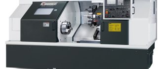
There are various options for classifying CNC metal-cutting machines. Depending on what main types of processing they are intended for, CNC machines belong to one of the following technological groups - turning, milling, drilling, jig boring, drilling and milling (milling and boring), drilling and milling and boring, grinding, multi-purpose (multi-operational), machining centers intended for electrical processing, etc.
Depending on the principle of motion control determined by the CNC system, machine tools belong to one of three groups - the first is represented by equipment with CNC positional systems, the second - with contour CNC systems, and the third includes machines with combined CNC systems.
Depending on the number of tools used, machines can be single-tool or multi-tool. Multi-tooling equipment uses up to 12 machines. Those that are able to provide the highest concentration of operations have over 12 instruments. They are equipped with a special magazine to accommodate them. Such equipment is called multi-purpose.
Using multi-purpose CNC machines, a large number of operations are performed with one installation of a part on the machine, which becomes especially important with a significant number of transitions.
It is more expedient to use a console-less layout of medium-sized machines equipped with a cross table and a horizontal or vertical spindle (in the first case, a built-in rotary table is often used).
This arrangement is more rigid in comparison with the cantilever placement of the table, which increases the accuracy of processing, and due to the constant height of the table, the equipment is equipped with devices that allow you to automatically change workpieces. Using single- or double-column CNC machining centers with longitudinal table movement, you can process long parts. This arrangement of equipment is also more rigid in comparison with machines equipped with a cross table.
Machining technologies require that cutting tools experience significant stress, high temperatures, friction and wear, and therefore have special operating requirements. The working part of the tools must be made of materials of great hardness that can withstand increased stress in bending, tension, compression, and torsion.
Also, the materials from which the tools are made must remain hard under the influence of high heating temperatures (have high red resistance). A very important characteristic of a tool material is wear resistance. The higher it is, the slower the wear of the tool will occur and the higher its dimensional stability will be, i.e., the variation in the size of parts sequentially processed with the same tool should be minimal.
Successful technology for machining parts requires as little as possible content of scarce elements in the materials from which cutting tools are made.
- Carbon tool steels
contain 0.9–1.3% carbon. The tools are made from high-quality steels U10A, U11A, U12A. As a result of heat treatment of steel (HRC3 60-62), their red hardness is +200...+250 °C. At this temperature, the hardness of the steel decreases significantly and the tools become unsuitable for cutting. The use of such steels is limited, since the permissible cutting speed cannot be more than 15–18 m/min. They are used for the production of taps, dies, hacksaw blades, etc. - Alloyed tool steels.
They are based on carbon steels alloyed with chromium X, tungsten B, vanadium F, silicon C, etc. The red resistance of such steels (HRC3 62-64) after heat treatment is +250...+300 °C.Alloy steels differ from carbon steels in their increased toughness in the hardened state, higher hardenability, and less tendency to deformation and cracks during the hardening process. The permissible cutting speed varies from 15 to 25 m/min. Broaches, drills, taps, dies, and reamers are made from steels 9ХВГ, ХВГ, ХГ, 6ХС, 9ХС and others.
- High speed steels
containing 8.9–19% W, 3.8–4.4% Cz, 2–10% Co and V. Cutting tools are made from steels R9, R12, R18, R6MZ, R6M5, R9F5, R14F4, R18F2, R9K5 , R9K10, R10K5F2, R10K5F5. The red resistance of heat-treated high-speed steel tools (HRC3 62-65) is +600…+630 °C.The tool is characterized by increased wear resistance and the ability to work at speeds of up to 100 m/min. Tools of simple shapes (cutters, milling cutters, countersinks) are made from P9 steel. Shaped and complex tools (for cutting threads and teeth), which must be highly wear-resistant, are made of P18 steel.
- Cobalt high-speed steels
(R9K5, R18K5F2, R9K10) are suitable for the technology of machining parts in the manufacture of which difficult-to-process corrosion-resistant and heat-resistant steels and alloys were used - they are recommended for use when working in difficult conditions (with heavy intermittent cutting, vibration, poor cooling conditions). - Vanadium high-speed steels (R9F5, R14F4)
are used for the production of tools that are used to perform finishing (broaching, reaming, counterbore). They are suitable for working with parts made of difficult-to-cut materials when cutting chips with a small cross-section. - Tungsten-molybdenum steels (R9M4, R6MZ)
are recommended for the production of tools used for roughing; broaches, cutters and other tools are also made from them. Savings in high-speed steels are achieved through the production of prefabricated and welded tools. For the working part of the tool, high-speed steel is used, welded from carbon steel 45,50,40Х, etc. with a shank. Often, high-speed steel plates are used, welded to toolholders or tool bodies. - Metal-ceramic alloys
are a solid solution containing tungsten, titanium and tantalum carbide (WC, Ti C, Ta C) in metal cobalt (Co).Hard alloys are used in the form of plates produced by powder metallurgy, which have a specific shape and size. The plates are pressed and then sintered at temperatures from +1500 °C to +1900 °C. There is a division of hard alloys into several groups - tungsten is represented by alloys VK2, VKZ, VKZM, VK4, VK4V, VK6, VK6V, VK8, VK8V, VK10, VK15, VK20, VK25; titanium-tungsten includes alloys T30K4D15K6, T14K8, T5K10, T5K12V; titanium-tantalum tungsten - TT17K12, TT10K8B.
Carbide inserts (HRC3 86-92) are characterized by such qualities as high wear and red resistance (+800...+1000 °C), due to which the processing speed can be 800 m/min. The plates are soldered to holders or tool bodies using copper (brass) solders or attached mechanically.
- Mineral ceramics
is a synthetic material, the basis of which is alumina (A12 Oz) sintered at a temperature of +1720...+1750 °C. The red resistance of TsM-332 mineral ceramics (HRC 91-93) is +1200 °C. This material is highly wear-resistant and is used for the production of tools that require high dimensional stability. Due to its slight affinity with metals, the material does not stick to the workpieces.Tools using mineral ceramic inserts are suitable for semi-finishing of parts made of steel and non-ferrous metals under non-impact loading.
To increase the performance characteristics of such instruments, elements such as W, Mo, B, Ti, Ni are added to mineral ceramic plates. Such materials are called cermets. Cermets are of particular importance in the technology of machining parts made of difficult-to-machine steels and alloys.
- Diamonds
belong to a special group of materials. In industry, both natural (A) and synthetic diamonds of the ASO, ASR, ASB, ASC, ACC, ACM, ASN grades are used. This is the hardest material with increased red and wear resistance.Diamond cutters are widely used in such technologies of mechanical processing of parts as fine turning or boring of elements consisting of aluminum alloys, bronzes, brass and non-metallic materials.
Using diamond tools, they work with parts made of hard and semiconductor materials, germanium, silicon, ceramics, heat-resistant steels and alloys. When using such a tool, the quality of processed surfaces increases significantly. The processing speed is over 100 m/min. The surfaces of workpieces treated in this way are characterized by low roughness and high dimensional accuracy, since diamonds are characterized by significant dimensional stability.
Pressure treatment
If mechanical types of metal processing are not suitable and it is necessary to maintain the integrity of the workpiece, craftsmen can use equipment that works with pressure. Technological processes in this case are divided into two groups:
- Stamping. This method uses two key elements - a punch and a die. The workpiece being processed is placed between these parts. Then, with the help of force, it moves. The workpiece takes the form of a matrix. There is hot and cold stamping. In the first option, the part is initially heated.
- Forging. In ancient times, blacksmiths forged weapons and armor. To do this, the workpiece was heated in a forge, and after that it was struck with a hammer. This changes the structure of the material and improves its characteristics.
Nowadays, forging uses pneumatic hammers and industrial furnaces.
Features of metal processing
Numerous types of metalworking can be classified into one of the large groups:
- mechanical (cutting);
- casting;
- thermal;
- pressure;
- welding;
- electric;
- chemical
Casting is one of the most ancient methods. It consists of melting metal and pouring it into a prepared mold that repeats the configuration of the future product. This method produces durable castings of various sizes and shapes.
Other types of processing will be discussed below.
Chemical treatment
To understand how chemicals affect the workpiece, you need to know how to process the metal. Chemicals are used to clean metal surfaces from rust and dirt. Also using a galvanic process to apply a protective coating to the workpiece. Chemicals improve resistance to corrosion processes. There are several methods for treating material with chemicals:
- Cementation - the metal is saturated with carbon.
- Boriding - when a material is saturated with boron, its wear resistance increases.
- Chrome plating - only the top layers of metal are saturated with chromium. Resistance to corrosion processes increases, but strength does not change.
- Nitriding is used to increase the resistance of metal to moisture and mechanical damage.
The materials can also be coated with a protective layer of aluminum.
Turning principle
Turning is a type of machining of continuously rotating workpieces, which is used to create parts such as rotating bodies by removing excess material.
Turning requires a lathe, a workpiece, a clamping/holding fixture, and a cutting tool. The workpiece is a fragment of a rolled profile with a round cross-section, which is fixed in a working fixture. The latter, in turn, is itself attached to the lathe, allowing its rotation at a fairly high speed. The cutter that performs the shaping is usually a single-point (sometimes multi-point) cutting tool, which is also fixed in the lathe. The cutting tool is fed to the rotating workpiece and, in the process of forceful contact with it, cuts off the material in the form of small chips.
In the production of rotating, usually axisymmetrical parts, turning is used for:
- Obtaining holes - smooth and for subsequent threads.
- Production of grooves and fillet grooves.
- Obtaining conical surfaces.
- Performing stepped diametrical transitions.
Turning can also produce shaped surfaces. For this purpose, automatic machines or turning machining centers are used, which have the ability to automatically reinstall the cutter/cutters.
Parts that are manufactured exclusively by turning are often used with a limited production program. These can be reference prototypes of shafts or fasteners, which are produced to order and then used to develop technological solutions in mass production. Lathe processing is often used as a secondary (or finishing) process when it is necessary to introduce some characteristics of the contour of a part to improve its geometric characteristics obtained, for example, by hot stamping. Thanks to the close tolerances and high surface quality that turning can offer, the process is ideal for creating precision parts such as rotary bodies.
Heat treatment
Metal processing technology using increased temperature is used to improve the characteristics of the material. In addition to proper heating, the part must be cooled at a certain speed. Heat treatment is divided into several operations.
Heat treatment of metal
Annealing
To improve ductility and malleability, an annealing process is applied to the workpiece. Its essence is to heat the material to a certain temperature and then leave it to cool in the oven. This process is most often carried out after casting. This way internal tension is relieved.
Hardening
First of all, the material is heated to the melting point. Then it is kept in this state for a certain period of time. During this time, the structure of the material changes. It becomes stronger. After heating, the workpiece is immersed in water or oil for rapid cooling. Metal processing by hardening is carried out in order to increase the hardness of the material. However, this reduces its viscosity and increases fragility.
Vacation
This technological process is performed after hardening. During tempering, the material is heated to a certain temperature and then slowly cooled. The fragility of the part is reduced.
Aging
It is considered one of the ways to decorate material. The workpiece is slowly heated to a certain temperature. After this technological process, the metal changes to such a visual state as if it had aged for a long time under natural conditions.
Normalization
To increase the malleability of the material without compromising the hardness index, the workpiece is normalized. During this process, the metal takes on a fine-grained structure.
The device of a universal screw-cutting lathe. Lathe group machines
Parts of various classes (round and non-round rods, rings, disks, body parts) are processed on a universal screw-cutting lathe. The universal screw-cutting lathe (Fig. 13) has a bed 18 - a massive base cast-iron part on two pedestals.
The main electric motor is installed in the front cabinet 16, and the pump and reservoir for COTS are installed in the rear cabinet 12.
The upper part of the bed has two pairs of guides for basing and moving the moving elements of the machine. Headstock 1 is attached to the left side of the bed. In the headstock housing there is a gearbox and spindle 2, which is a hollow shaft, on the right threaded end of which technological equipment for basing and securing workpieces (three-jaw chuck 3, faceplate, etc.) is installed.
A
b
Rice. 13. Diagram of a universal fuel assembly (a): 1 – front headstock; 2 – spindle; 3 – three-jaw chuck; 4 – rotary slide; 5 – tool holder; 6 – transverse slide; 7 – quill; 8 – tailstock; 9 – rack; 10 – running shaft; 11 – lead screw; 12 – rear cabinet; 13 – pallet; 14 – longitudinal slide; 15 – apron; 16 – front cabinet; 17 – guitar innings; 18 – bed; FA diagram - 1M63N-3 (b)
The spindle receives rotation (main movement) from the main electric motor through a V-belt drive, a system of gears and couplings located on the shafts of the gearbox located inside the headstock. The tailstock 8 is installed on the right side of the frame with the ability to move along its internal guides. Inside the tailstock there is a retractable quill 7, into the conical hole of which various centers are inserted (fixed, rotating, floating, plug center).
When processing short workpieces, workpieces of the “non-round rod” type or body workpieces, an axial tool (drill, countersink, reamer) is installed in the conical hole of the quill, which allows axial processing of the central hole in the workpiece. The feed movement is carried out manually by rotating the tailstock handwheel. On a pair of outer guides of the frame there is a support consisting of a tool holder 5, a rotary slide 4, a transverse slide 6, a longitudinal slide 14 and an apron 15 (Fig. 13). The four-position tool holder holds cutting tools – turning tools.
The rotary slide is installed with the ability to rotate and fix around a vertical axis, which allows you to process short (up to 150 mm) conical surfaces with large cone angles (up to 45°).
When processing long conical surfaces with small cone angles (up to 5°), the axis of rotation of the workpiece is shifted by moving the tailstock perpendicular to the bed guides.
The cross slide allows you to give the cutting tool a feed movement Ds at an angle of 90° to the axis of rotation of the workpiece (cross feed). The longitudinal slide allows you to give the cutting tool a feed movement Ds at an angle of 0° to the axis of rotation of the workpiece (longitudinal feed). The feed movement is carried out manually or automatically.
On the front wall of the frame there is a feed box, kinematically connected to the spindle by a system of gear wheels installed in the feed box 17. The feed box transmits movement to the lead shaft 10 and the lead screw 11. The lead screw serves to ensure automatic feed only when cutting threads, to ensure automatic For other jobs, the running shaft serves as a feed.
To convert the rotation of the lead shaft or lead screw into linear movement, mechanisms located in the apron are used (a “screw-nut” type mechanism for transverse or longitudinal feed during thread cutting, a “rack-wheel” type mechanism for other work). In this case, the rail 9 is installed on the front part of the frame. To collect chips and COTS, a tray 13 is installed in the lower part of the frame (Fig. 13).
A universal screw-cutting lathe allows you to install no more than five cutting tools (four in the tool holder and one in the tailstock quill). For the production of a batch of parts with a large volume of turning, universal machines are of little use, since it takes a lot of time to install and adjust the cutting tool.
Rice. 14. Cartridge turning-turret semi-automatic : 1 – bed; 2 – feed box; 3 – front headstock; 4 – front stop drum; 5 – transverse support; 6 – turret head; 7 – turret support; 8 – rear stop drum
To process a batch of complex parts such as a stepped roller, flange, ring, turret lathes are used. In a turret lathe, several cutting tools are mounted in a “turret”, which reduces the time required to set up and set up tools. In bar revolving machines, the workpiece (bar of various sections) is clamped in a hollow collet chuck. After manufacturing the part, it is cut off, the remaining part of the rod is pulled through the hollow axial hole of the collet chuck and the next part is processed. In cartridge turret machines, piece workpieces are processed by clamping them in the jaw chuck of the machine.
Turret machines with a multifaceted turret are additionally equipped with one or two (front and rear) transverse supports. All tools working with longitudinal feed motion are fixed in the turret. All tools that work with a transverse feed movement are fixed in supports. Machines with a round turret head do not have transverse supports. If necessary, the transverse movement of the feed is carried out by slowly rotating the turret around a horizontal axis. In Fig. 14 shows a cartridge turret machine with a multi-faceted head. It consists of a frame 1, a headstock 3 with a gearbox 2, located on the front side of the frame, a transverse support 5, a turret support 7 with a turret head 6, front 4 drums and rear horns.
Increased processing productivity is achieved through parallel operation of the supports and preliminary adjustment of the machine to the stops of drums 4 and 8. Setting the machine to the stops allows you to automatically maintain the diameters and lengths of the workpiece surfaces being machined.
Processing of stepped shafts is carried out on multi-cutting semi-automatic lathes, automatic machines or hydrocopying lathes.
Processing of massive cylindrical workpieces with a ratio of the length of the workpiece to its diameter of 0.3–0.4 is carried out on rotary lathes.
Features of artistic processing
The basics of metalworking include not only changing the shape and size of the workpiece, but also their decorative processing. The master can create individual products, or decorate ready-made metal structures. There are 4 metalworking processes that allow you to change the appearance of a part:
- casting;
- forging;
- minting;
- welding.
All types of decorative work with metal involve initial heating of the workpiece. The higher the plasticity, the easier it is to work with parts.
Welding technology is considered new compared to others. Its active development begins in the second half of the 20th century. Using a welding machine, you can cut metal sheets and connect the parts together.
Metal is a hard material, when working with it you need to use special equipment and heat the workpiece. Processing allows you to change the size and shape of a part, as well as improve its technical characteristics. Using methods of decorative work with material, you can decorate products, improving their appearance.
Milling
The purpose of the operation is to form a profile of straight and curved workpieces. The concept of the “milling” operation should be distinguished from the milling processing method. The milling operation is universal, as it allows you to obtain any shape of the part. The following operations are performed using the milling method: creating a base surface; processing to size; milling of complex profiles; formation of spikes and eyes. Depending on the processing height, milling machines are divided into light (up to 80 mm), medium (up to 100 mm); heavy (up to 125 mm).
In Fig. Figure 1 shows some types of part profiles when processed on milling machines.
Rice. 1. Types of profiles when processed on milling machines
Milling work for the final processing of workpieces, according to the method of their implementation, is distinguished into four types: milling of straight surfaces along a ruler (through, not through); milling curved surfaces using a ring and a template; milling of double curvature surfaces; face milling.
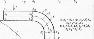
The principle of milling straight (curvilinear) and profile surfaces of workpieces is shown in Fig. 2.
Non-through milling (Fig. 2, d) is characterized by the fact that the profile is not milled along the entire length of the workpiece, but only on some part of it. Non-through milling is performed on a milling machine using stops installed on a ruler. Part 1 is laid flat on the machine table, one end of the part rests against the front stop 3, and the other end is pushed onto the cutter 4 until the edge touches the front guide ruler 5. Then the part moves along the ruler to the second rear stop 6 and the end its closest to the cutter is retracted from ruler 5.
In Fig. Figure 2 shows the milling of one curved edge with the lower (b) and upper (c) location of the ring and template. Template 2 with its base edge rests on support ring 4, located coaxially with cutter 3; blank 1 is installed on the template.
Rice. 2. Scheme of processing parts on milling machines: a, b – milling edges along a guide ruler; c – through milling; d – milling along stops; d – milling according to the template and the lower support ring; 1 – rear guide ruler; 2 – bolt for fastening the guide ruler; 3 – milling head; 4 – arc of the guide ruler; 5 – front guide ruler; 6 – workpiece; 7 – machine table; 8 – emphasis; 9 – template (tsulaga); 10 – clamp; 11 – washer; 12 – support ring
Curvilinear edges of an open and closed contour are obtained by milling along a ring and a template. The edge profile is obtained using a profile cutter; the curvilinearity of the edge is determined by the shape of the template. In accordance with the shape of the part, the template can be a closed contour, in which the workpiece is processed along the entire perimeter of the edges, or an open contour - one, two, or three edges are processed.
The template is manually moved towards the rotation of the cutter, while simultaneously pressing it against the support ring. The cutter, processing the edges, copies the curved shape of the template on the workpiece. The support ring can be placed at the bottom or top of the cutter. Accordingly, the workpiece being processed will be based either on the template or under the template on the machine table. The upper position of the ring makes working on a milling machine less dangerous.
The cutting area is covered with a template. In this case, the workpiece is placed directly on the milling machine table. With the correct shape of the base surfaces of the workpiece, you can obtain a more accurate position of the profile along the width of the workpiece. But at the same time, the spindle runout amplitude, transmitted through the ring and template to the workpiece, increases. To eliminate the transmission of spindle vibration through the ring and template to the part, it is advisable to fix the ring not on a rotating spindle, but on a special fixed bushing, which is attached to the milling machine table coaxially with the spindle.
The support ring is usually placed at the top when processing panels and frames. The lower location of the support ring is usually used when processing bars. To produce parts with complex curved shapes, automatic copying and milling machines are used.
A separate group consists of milling machines, in which a rotating cutter processes the workpiece from all sides (volumetric milling), copying the given shape of the model. They produce asymmetrical products in the longitudinal and transverse directions. Machines can be single- or multi-spindle.
Face milling of grooves, pockets and complex contours of workpieces is performed on copy milling machines with an overhead spindle. In Fig. Figure 3 shows a milling diagram on an end-face copy-milling machine .
Processing of part 2 is carried out in a special template 4 with grooves on the underside corresponding to the contour to be processed.
In the table 1 of the machine there is a copier finger 5 protruding above its plane, which during operation is located in the groove of the template. The movement of the template on the table is determined by the shape of the groove it has.
Rice. 3. Scheme of milling parts on an end copy-milling machine: 1 – table; 2 – detail; 3 – cutter; 4 – template; 5 – copier finger
The choice of the type of equipment depends on the type of milling work (shape of the part), and the model of the machine - on the dimensional characteristics of the workpiece, the desired productivity, and the flow chart of the technological process. To perform various milling jobs, you can use, for example, the following equipment:
- milling of straight surfaces - single-spindle milling machines with a lower spindle with manual feed FL (light) and FL-1, FS-1 (medium), FT (heavy) and FT-1; with mechanical feed FLA, FSA and FSA-1, FTA and FTA-1;
- formation of tenons and lugs - single-spindle milling machines with a lower support position with a tenon-cutting carriage FLSH, FSSh, FTSh and similar machines with mechanical feed FSS-12 and FTSh-12;
- milling curved surfaces:
- single-spindle milling machines with a lower spindle position FA-4, FSK, FSK-1, FL, FL-1, FS-1, FT, FT-1. Milling is done using a ring and a template;
- rotary milling machines with an overhead spindle: single-spindle F1K and F1K-2, double-spindle F2K-2; F2K-3 are widely used in the mass production of bar products;
- face milling - copy milling machines with an overhead spindle VFK-1 and VFK-2 and a similar machine with driven removable rollers for moving the template VFK-3. Processing is done using a copier and a template. The accuracy of processing on these machines is largely determined by the accuracy of the template.
Schemes for organizing workplaces for milling machines are shown in Fig. 4–7.
Rice. 4. Organization of workplaces for a single-spindle milling machine with a lower spindle FS, F = 10.8 m2
Rice. 5. Organization of workplaces for a single-spindle milling machine with a lower spindle with an FSSh carriage, F = 10.2 m2
Rice. 6. Organization of workplaces for a single-spindle rotary milling machine
Rice. 7. Organization of a workplace at the VFK-2 milling copying machine, F = 10.5 m2
Welding
This type of metal processing, such as welding, is used when it is necessary to obtain permanent connections between metal elements. This technology is used everywhere (in large and small enterprises, in the repair of metal structures). You can connect parts in different ways:
- overlap;
- joint to joint;
- corners.
Metal processing in this method is carried out on semi-automatic or automatic welding machines, using hand tools. An electric arc or gas flame is most often used as a heat source. Less commonly, the joining of parts occurs due to thermal friction, ultrasound, laser energy or another type of influence.
Automatic machines do not have wide functionality. The operator presets the program. This is where human participation in the process ends. This method is used in the manufacture of a large number of products.
When working with semi-automatic equipment, the process is controlled by the operator, and additives are supplied to the desired zone through a special mechanism.
Over the last century, many new types of welding have been developed. Plasma, electro-beam and thermite technologies have gained popularity. In the first case, the parts are connected with ionized gas, forming an electric arc. In addition to welding, this type of equipment can cut metal workpieces.
If you need a deep (up to 20 cm) or small (up to 10 mm) seam, it is better to use electro-beam technology. Its specificity lies in the fact that metal processing occurs in a vacuum. This welding method is used infrequently, which is explained by its specifics.
Thermite type of welding is used:
to eliminate cracks and defects in previously made seams; if you need to ensure high quality connections of metal structures.