Rotary milling machines
TO
category:
Woodworking machinery
Rotary milling machines
Next: Woodworking Machine Cutting Tools
Design
Rotary milling machines are used for processing along the outer contour of workpieces and curved components of significant size. These machines are highly productive; their use is especially effective in enterprises with mass production of products. Unlike milling machines with a lower spindle position, in rotary machines the axes of the spindles are movable during operation and move relative to the workpiece fixed in the workpiece along a special copier, the shape of which determines the processing profile of the workpiece. The domestic industry produces single-spindle and double-spindle rotary milling machines. On dual-spindle machines, the workpiece (assembly) is processed simultaneously by two cutters, resulting in a lower roughness of the machined surface,
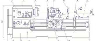
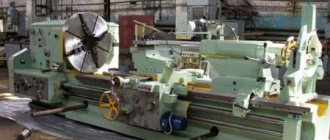
Rice. 1. General view of a two-spindle rotary milling machine: 1 - support, 2 - guide head, 3 - spindle electric motor, 4 - brackets, 5 - clamp with pneumatic drive, in - stand, 7 - table, 8 - control panel, 9 - copy roller . 10 — cutter, 11 — handwheel for installing the caliper, 12 — handwheel for installing the spindle, 13 — cam
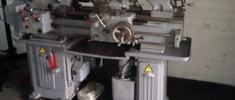
A two-spindle rotary milling machine (Fig. 1) has a movable round table, two supports movably mounted in the guide heads of cylindrical racks. Electric motors are mounted on the supports, the shafts of which also serve as spindles. Sliding brackets for pneumatic clamps are installed on the stand in the center of the table. Machine control buttons and signaling devices are located on the panel.
Rice. 2. Kinematic diagram of a two-spindle rotary milling machine: 1 - replaceable gears, 2 - clutch, 3 - worm pair, 4 - lever, 5 - spindle electric motor, 6 - caliper, 7 - pneumatic cylinder piston, 9. 10 - handwheels, 11 — copy roller, 12 — rheostat roller, 13 — gear sector, 14 — table drive motor
The workpieces are placed in special tsulagi, fixed on the table, but the circumference of which can be secured with cams that automatically reduce the feed speed (table rotation) at the time of processing individual sections of the workpiece, which helps to avoid the formation of chips.
The design of the machine provides the ability to change the direction of movement of the spindles relative to the table axis. The support is raised and lowered using the handwheel (Fig. 2), and the spindle relative to the support is used with the handwheel; the position of the copy roller relative to the spindle axis is changed using the handwheel. All these movements are needed to set up the machine.
The feed mechanism (table rotation) is driven by a DC electric motor through worm, gear, cylindrical and again worm gears. The feed speed is changed by changing the spur gears. To start and stop the table without turning off the electric motor, a clutch is provided, controlled by a lever located at the workplace. The feed speed is reduced by the impact on the transformer of a cam mounted on the table, which is transmitted through the sector with the roller. The transformer is electrically connected to the excitation winding of the DC generator, which serves as a power source for the electric motor.
During operation, the support roller is constantly pressed against the copying pad mounted on the table. For this purpose, I warn you that the pneumatic drive is inspected. The pneumatic drive cylinder is fixed to the support port, and the hollow rod is fixed motionless. The clamps of the machine are also powered by a pneumatic drive.
Rice. 3. Diagram of the pneumatic drive of a two-spindle rotary milling machine: 1 - clamp. 2 - flexible hoses. 3 - spool valve, 4 - piston, 5 - caliper with pneumatic cylinder, 6 - oiler, 7 - receiver, 8 - purge valve, 9 - pressure switch, 10 - pressure regulator
The pneumatic drive of the machine (Fig. 3) includes a hydraulic pressure valve, through which the working gas under constant pressure is supplied to the receiver, and from it into the cavities of the pneumatic cylinders of the calipers. To lubricate the cylinder walls, a sprayer is provided, through which the working fluid is introduced into the working gas entering the cylinders.
In clamps with a pneumatic motor, the working gas is supplied through a cavity in the center of the machine table, where a spool pneumatic device is installed, which ensures the supply of compressed working gas only to the cavities of those clamps that are currently located near the working cutters. The cavities of other clamps are connected at this time to the exhaust line, which is necessary for removing processed workpieces and inserting new ones. The spool valve operates automatically. To install it, a lever is provided, by turning which you can change the operation of the clamps, connecting some of them to the compressed working gas line, and others to the atmosphere.
The pressure line includes a pressure switch, which, when the air pressure in the pneumatic network is below the set limit, automatically turns off the machine drive. The relay does not allow turning on the machine even if there is no working gas pressure in the system. This is very important to ensure safe operation of the machine.
Setting up machines
The workpieces to be processed are placed in templates (Fig. 4), which are installed and secured on the machine table with bolts with square heads inserted into T-shaped radial grooves specially provided in the table. Depending on the shape of the part and the requirements for the roughness class of its surface treatment, the workpiece is processed with one cutter in one pass or with two sequential cutters that remove chips from the same plane of the workpiece (roughing and finishing milling) or, finally, with two sequential cutters, rotating in different directions and removing chips from different areas of the same workpiece plane. The last case is the most difficult to configure.
Suppose you need to set up a machine for processing workpieces in order to obtain the part shown in Fig. 4, a. Part of the workpiece plane must be processed during down milling, otherwise chipping may occur, and part II of the plane must be processed during up milling (feed direction is shown by an arrow).
To secure the workpieces, tsulagi must be made with two copying rulers: one for a support with a cutter rotating in the direction of feed, the second for a support with a counter-rotating cutter. The rulers are fixed on the tsulag one above the other. The tsulag must provide for the possibility of basing the workpieces along the bottom surface, edge (opposite to the one being processed) and the end.
Rice. 4. An example of installing sulags on the table of a rotary milling machine: a - sketch of the part; I - section of the edge processed during down milling, II - the same, during up milling; b - table with tsulags; 1, 2 - copy rulers, 3 - workpiece, 4 - template end stop, 5 - template, 6 - machine table
The tsulagi are placed on the machine table as close as possible to its edge in such a way that the distances (Fig. 166, b) from the edge of the table to the end edges of the tsulagi are equal to each other. The upper plane of the tsulagi installed on the table must be strictly horizontal, which is checked by a level placed on the plane of the tsulagi along the radius of the table and then perpendicular to the radius. Bolts are inserted into the holes provided in the trays, the heads of which are first inserted into the grooves of the table. After final alignment, the cages are secured with nuts.
Having placed the workpieces in the tsulagi, they begin to install the clamps. To do this, loosen the locking screws on the racks of the sliding brackets and, lifting the clamp up, insert its rack into the hole provided in the tray so that there is a gap of 3-4 mm between the clamp shoe and the upper surface of the workpiece and so that the shoe in the lower position is parallel to the surface blanks. Having installed the clamps, they are fixed by tightening the locking screws of the sliding brackets.
After installing the clips and clamps, the calipers are adjusted. The cutters are fixed on the spindles, and the calipers are adjusted in height in accordance with the position of the workpieces in the holders. The cutters are installed more carefully relative to the workpieces using a spindle screw mechanism. It should be noted that during profile processing, even a slight displacement of the cutters relative to the workpiece face can cause defects. Therefore, when setting up a machine for profile processing of workpieces, previously processed workpieces or special templates are placed in the tsulags. The cutters are brought close to the workpiece and, by moving the spindle in a vertical plane, they ensure that there is no gap between the cutter and the workpiece, that is, the profile of the workpiece completely coincides with the profile of the part of the cutter touching the workpiece.
The copy rollers are moved towards the tsulag. The rollers are considered correctly installed if, in the extreme position of the caliper, they are tightly adjacent to the supports. The cutters, when turning them by hand, should lightly touch the surface of the processed workpiece. At this point, the preliminary setup is considered complete.
After processing 4-5 workpieces, their dimensions and shape are checked and, if necessary, the position of the copy rollers is adjusted. For example, if the workpieces after processing are smaller in width than provided for in the technological map, the rollers are slightly extended, thereby reducing the thickness of the removed chips, and vice versa. By turning the handle of the spool pneumatic device, the zones in which the workpieces must be clamped are established.
Working on machines
Before starting work, open the compressed air valve and check its pressure using a pressure gauge. Connect the machine to the AC mains and turn on the frequency converter, then turn on the spindle motors and then the feed drive.
The machine is operated by two workers. The machine operator removes the processed workpieces from the table and passes them to another worker, who places the workpieces in a stack. The machine operator takes unprocessed workpieces from another stack and places them in templates. The machine table can make up to 3-5 revolutions per minute (at maximum feed). Each workpiece must be accurately installed in the tsu-lag, i.e., tightly adjacent to it with its base surfaces, otherwise defects are inevitable. If the machine operator sees that at a given feed rate he cannot fulfill this condition, the feed rate should be reduced slightly. During work, it is periodically necessary to check the dimensions of the processed workpieces with clamp gauges. The roughness of the treated surface is determined visually.
It is necessary to constantly monitor the operation of individual elements of the machine. This especially applies to electric spindle motors. Overheating of engines often occurs due to excessively large allowances left for processing, due to incorrect distribution of the layer of chips being removed between cutters mounted on different spindles (when sequentially processing the same surface with two cutters simultaneously).
In the first case, you should reduce the feed speed and at the same time inform the technician about the noticed defect. If the electric motor continues to heat up when operating at a reduced feed rate, you need to transfer the workpieces for additional processing, for example, to a band saw to remove excess allowance.
Motors can also overheat when working with dull cutters. In this case, it is necessary to change the cutters, not forgetting to check the installation of the caliper copy rollers.
Specifications
Full technical specifications are described in the instruction manual.
- The installed workpiece can have a maximum of the following parameters in terms of weight, height and diameter: 4000 kilograms, 1000 and 1250 millimeters, respectively.
- 11200 is the diameter of the platform itself.
- 5-250 rpm – angular speed for the faceplate.
- The tool feed rate is 0.03-12.5 revolutions per minute. In total, this and the previous indicators have up to 18 steps.
- 5-1800 – speed according to installation movements.
- The power of the main movement is 30 kW.
- 16.5 is the total mass for installation.
CNC models
CNC lathes do not have a side support, since the design of the support is significantly more complicated.
Many people prefer to manufacture the required parts on this equipment for the following reasons:
- The control unit allows you to set the number of revolutions of the faceplate. In this case, the operator can set parameters with high accuracy.
- For work, tools can be installed whose cutting edge is made of wear-resistant steel. Due to this, you can significantly speed up the cutting process.
- Processing is often carried out automatically under computer control, which greatly simplifies the use of thread-cutting models. Indeed, in many cases, it is the error made by the operator that becomes the cause of the defect.
- To use such equipment, it is enough to have a technologist on staff who must write a program to obtain certain parts.
- The accuracy of the resulting dimensions can be very high. The machine of this group can be boring or universal, designed to perform other operations.
- The electrical circuitry of modern machines can significantly reduce electrical costs. For this purpose, electric motors with high efficiency and efficiency are installed. Like conventional models, the CNC version is equipped with several electric motors, each responsible for performing certain tasks.
CNC turning lathe
In general, we can say that the future of various manufacturing industries lies with CNC machines. They have increased productivity and allow the production of high-precision parts. At the same time, the dimensions of the structure are reduced every year, and the processing area is covered with a protective casing.
How do rotary lathes work?
The structure rests on a hollow post cast from cast iron in a vertical position. All other components connect to this part.
Main node devices
There are not many components in the desktop:
- Faceplate.
- The previous part is installed complete with the spindle.
- A mandatory addition is supports in a cast iron housing with bearings.
- Drive device.
The design is equipped with cylinder-shaped, roller-type bearings. They are mounted to center the platform and control radial forces during cutting. The radial clearance parameters in the supports are individually selected. To do this, using adjusting nuts, tighten the inner rings, which have a conical surface.
Frictional forces and the weight of the workpieces create an additional load that is transmitted to the ring guide responsible for sliding. This part has central lubrication. A cylindrical helical gear imparts rotational force to the faceplate. The force itself is directed from the drive shaft. The latter is tied to the main drive responsible for movement.
Speed control box
Popularly, such a knot is also called the “carousel pig”. Performs a function related to the transmission of torque, starting from the drive motor and ending with the spindle on the desktop.
In addition, the part allows you to set the required peripheral speed for the spindle itself.
In total, the mechanism has up to 6 shafts. They use special gears to move power from one component to another. The components maintain constant engagement with each other. But the gears sit loosely on the shafts, there is no rigid clutch. The rotation acquires a certain frequency due to the commutation of couplings in the electromagnetic circuit. There are a total of 10 functions in the box that can be customized. Everything happens remotely.
Workpieces and faceplates are characterized by significant inertial masses, which increase the starting current by the time the engine starts. The platform is being accelerated in steps to reduce such risks. Switching on can be carried out in 2,3 or 4 stages, it all depends on the given speed.
Clutches can be switched during operation. Therefore, when turning surfaces, the speed remains constant.
The platform has a limited angular speed depending on the parameters of the workpiece that is currently being processed. For example, it is permissible to set no more than 80 revolutions with masses of 3.2 tons.
Vertical support unit
The part is equipped with a turret with 5 positions. It is needed for the tool; it moves in two planes:
- Vertically.
- Horizontally.
The first version of the scheme is provided by guides supporting the caliper. The second involves support on traverses and crossbars. Characteristic is the movement of the part itself vertically, along the rack. The gearbox is mounted on a traverse and is used as a displacement drive.
Vertical movement has its own characteristics:
- The movement itself occurs due to an independent drive, which has its own motor.
- The worm mechanism allows you to change positions if necessary. It comes from a separate electric drive.
- The caliper easily tilts up to 45 degrees in both directions.
- Thanks to this device, processing conical parts is not difficult.
Side caliper
Has the following features:
- Availability of 4-position tool holder.
- Duplication of orthogonal movements of the vertical support device.
The force of movement is transmitted by a gearbox mounted on the end of the mechanism. Why is it necessary to duplicate the movements of the second node? Processing accuracy increases when using such solutions. The instrumentation system operates with reduced elastic deformations. The implementation has several variants of schemes, which are selected individually for each situation. The central holes are processed using a vertical knot.
Design features
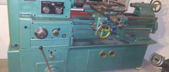
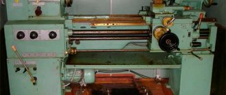
Conducting a review of the 1512 rotary lathe, we note that the layout of all components allows you to correctly position the cutting tool for large overall dimensions of the parts. The rotary machine 1512, the passport of which was included in the delivery set, consists of the following components:
- The table on which the workpiece is fastened. It is usually round in shape.
- Caliper and faceplate.
- The control unit is a pendant control panel. At the same time, it has a special suspension, which eliminates the possibility of the remote control getting into the cutting zone.
- The bed is quite large and made of cast iron. The bed is designed to dampen vibration and other loads.
- The 1512 rotary lathe has a crossbar, as well as a mechanism for moving along it.
- The model also has a horizontal caliper with a feed box.
Components of the machine 1512
In order for the device to have a long service life, lubricant is supplied to the rubbing elements. A special pump was installed for this purpose.
Purpose and scope
The numbers in the marking have the following interpretation, if we rely on the domestic classifier:
- 1 – assignment to a specific group of equipment. In this case it is turning.
- 5 – machine type. It's a carousel.
- 12 – characteristic describing the dimensions. 1250 millimeters is the maximum part size for processing.
The name “carousel” has its own history. Essentially, the term refers to how the installation is designed. The main parts include the faceplate with clamping elements. Rotation around a vertical axis makes the device similar to the rides of the same name. The lathe type of machine is the closest in properties to its competitors. They differ in a spindle with a traditional horizontal arrangement. The passport confirms this.
The purpose of both types of devices is turning parts with a short length. But it is the carousel variety that has a wide range of advantages.
- High-quality fastening of components and parts.
- Convenient loading of workpieces.
- The spindle is not subject to bending forces.
- Processing may take longer. 1 – parameter of the relationship between height and diameter.
Among the disadvantages, possible difficulties with chip removal are noted. Diametric measurements also turn out to be inconvenient for many.
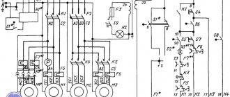
Electrical equipment of cantilever milling machines 6Р10, 6Р80, 6Р80Г, 6Р80Ш
General information
The electrical equipment installed on the machine is designed for a power circuit voltage of 380 V, 50 Hz three-phase alternating current. The following voltages are used in the control circuit:
- magnetic starter circuit ~ 110 V;
- electrodynamic braking circuit ~ 55 V;
- electromagnetic clutch circuit - 24 V;
- local lighting circuit ~ 36 V;
- signal lamp circuit ~ 22 V.
The machine is equipped with three three-phase squirrel-cage asynchronous electric motors.
Technical data of electric motors are given in the list of electrical devices attached to the circuit diagram. Electric motor for driving the milling head, type AOL2-21-4-S2, 1.1 kW, 1400 rpm, version M301.
The electrical ballasts are mounted in a wall cabinet on the right side wall of the machine.
The supply wires can be entered into the electrical cabinet from below or from above through a hole with a TDV6 3/4″ thread located in the elbow mounted on the rear side wall of the electrical cabinet. To connect from above, the lead-in elbow should be rotated 180°.
On the front side wall of the electrical cabinet there is a handle for the input switch, a signal lamp indicating the presence of voltage in the control circuits when the input switch is turned on, and a load indicator indicating the load of the spindle motor as a percentage of the rated one.
On the left side wall of the machine there are switches for the electric motors of the spindle, milling head, feed and electric pump, as well as a “Push” button, designed to briefly turn on the electric motors.
On the front wall of the slide there is a push-button station with buttons to start the machine, stop the machine and accelerate the movement of the table.
To quickly move the table, an MBH electromagnetic clutch is built into the feed box.
For better illumination of the part processing area, two local lighting lamps are installed on the machine.
Opportunities from a technological point of view
The main purpose of rotary machines is to process relatively flat parts with a round configuration. Among the possible preparations:
- Gears.
- Wheel installations.
- Flywheels.
- Lids.
- Flanges.
- Disks.
The installation uses standard tools, including reamers, countersinks, drills, heads with cutters, and the like. The main technological operations for the device include:
- Making holes using a rod tool.
- The function of boring through and stepped holes.
- Cutting grooves in the shape of a circle.
- Grinding of ends, ledges.
- External turning of parts in the shape of a cone or cylinder.
The range of operations performed expands with the addition of special equipment:
- Lapping, rolling using rollers.
- Sanding, superfinishing.
- Thread cutting.
- Deep drilling.
- Processing of nonlinear surfaces, including spherical ones.
Adjustable clamps make it easier to secure workpieces if necessary. The same goes for the cams. Small parts are installed in additional self-centering chucks.
Layout of electrical equipment on horizontal cantilever milling machines 6Р80, 6Р80Г
Layout of electrical equipment on machines 6Р80, 6Р80Г
Electrical equipment of milling machines of the Gorky Machine Tool Plant, GZFS
Electrical equipment of milling machines 6T12, 6T13, 6T82, 6T82G, 6T82Sh, 6T83, 6T83G, 6T83Sh
Electrical equipment of milling machines 6P12, 6P13, 6Р82, 6Р82Г, 6Р82Ш, 6Р83, 6Р83Г, 6Р83Ш , 6Р12Б, 6Р13Б
Electrical equipment of milling machines 6M12P, 6M12PB, 6M13P, 6M13PB, 6M82, 6M82Sh, 6M82GB, 6M83, 6M83Sh
Electrical equipment of milling machines of the Vilnius Zalgiris Machine Tool Plant
Electrical equipment of milling machines 6T10, 6T80, 6T80G, 6T80Sh
Electrical equipment of milling machines 6Р10, 6Р80, 6Р80Г, 6Р80Ш
Electrical equipment of milling machines 6N10, 6N80, 6N80G, 6N80Sh
Electrical equipment of milling machines of the Dmitrov Machine Tool Plant, DZFS
Electrical equipment of milling machines 6Р11, 6Р81, 6Р81Г, 6Р81Ш
Electrical equipment of milling machines 6N11, 6N81, 6N81G, 6N81A
What other features does the equipment have?
The following technical indicators of the units should be the main ones for buyers.
- Section of the washer.
- The speed at which the crossbar moves, specified for machines with two posts.
- Maximum distance of movement of supports, horizontal and vertical.
- Section with the height of the part to be processed.
- The number of revolutions of the faceplate.
- The angle for tilting the faceplate.
- Number of speeds.
- General power.
You can download the machine passport here.
When parts are processed by rotary mechanisms, high speeds are typically maintained. Serious cantilever loads do not harm the spindle; the use of a faceplate prevents damage. This part is placed on the structure in a special way to achieve the best result.
Information about the manufacturer of cantilever milling machines 6Р10, 6Р80, 6Р80Г, 6Р80Ш
The horizontal milling machine with a rotary table (universal) model 6T80 was produced by the Vilnius Machine Tool Plant .
The machine tool industry produced its first products in 1947. The plant first specialized in the production of drilling and cross-planing machines, then produced mainly horizontal, vertical, universal milling machines, semi-automatic milling machines, universal precision specialized milling machines
Machine tools produced by Vilnius Machine Tool Plant
- 6E80SH
- universal cantilever milling machine 200 x 800 - 6M80
- horizontal cantilever milling machine with rotary table (universal) 200 x 800 - 6N10
- vertical cantilever milling machine 200 x 800 - 6N80
- horizontal cantilever milling machine with rotary table (universal) 200 x 800 - 6N80G
- horizontal cantilever milling machine 200 x 800 - 6N80SH
- universal universal cantilever milling machine 200 x 800 - 6P80G
- horizontal cantilever milling machine 200 x 800 - 6Р10
- vertical cantilever milling machine 200 x 800 - 6Р80
- horizontal cantilever milling machine with rotary table (universal) 200 x 800 - 6R80G
- horizontal cantilever milling machine 200 x 800 - 6Р80Ш
- universal universal cantilever milling machine 200 x 800 - 6T10
- vertical cantilever milling machine 200 x 800 - 6T80
- horizontal cantilever milling machine with rotary table (universal) 200 x 800 - 6T80SH
- universal cantilever milling machine 200 x 800 - NS-12A
- tabletop drilling machine Ø 12 - SUS-1
desktop drilling machine Ø 12
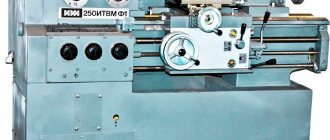
Domestic models of the 1512, 1516 and 1525 series
The Machine Tool Plant named after G. M. Sedin was the institution that was considered the main one among manufacturers during the Soviet era. In 1953 the first carousel unit appeared. Design in this direction was carried out by company specialists.
After that moment, rotating lathes became the main specialization of the plant. The machines of this enterprise are still actively used in many areas of industry. The 1512 and 1516 series are the most widely used. These are universal-purpose devices, with one rack. Purpose – small-scale processing of parts made of non-ferrous and ferrous metals.
The functionality of the machine is enough to perform any type of turning work.
Some variants of the devices had faceplates of a self-centering design. Due to this, the technical capabilities of the units began to expand.
Machine 1525 is a two-column type of equipment that was produced by the same Sedin plant. Distinctive features are reversible movements of the faceplate. There are also two upper rotary calipers. With the help of two clutches, the owner can easily select rotation frequency intervals in a given case. The speed at which the motor operates is adjusted by a transistor converter. For this, a stepless circuit is used.
The above types of machines are complemented by CNC if necessary. Then the devices operate on the basis of a software package.
Is it possible to assemble it with your own hands?
Before assembling the circuit yourself, you must first of all remember that the upcoming work involves electricity, and compliance with safety rules during its production is extremely important!
Required materials and tools
What we need:
- the basic electrical circuit of the milling machine itself;
- a set of constituent elements (magnetic starters, limit switches, transformers, control buttons, toggle switches, relays, etc.;
- an electrician's kit, which includes the necessary elements (pliers, screwdrivers, markers, electrical tape, etc.);
- cable products (cables, installation wires of different sections);
- electrical signal tester or multimeter.
Step by step assembly
It is advisable to start the assembly with the installation of the main components, first install the cables to the electric drives, wires to the magnetic starters. Then gradually move on to secondary control circuits, blocking, signaling, and protection circuits.
The ends of the cables and wire cores must be terminated and marked in accordance with the circuit diagram of the milling machine. This is extremely important because it will save more time and effort during commissioning. And you need to remember about those who will operate the machine after you.
Connection and service check
After installation, you need to make sure that all main work is completed and all foreign objects are removed from the operating area of the machine.
After power is supplied to the machine, you can begin to check its functionality. Check whether it is controlled by handles and control buttons, whether the spindle motor is braking, whether the longitudinal movement of the table is controlled, etc.
Possible errors and ways to fix them
- the engine hums when starting, but does not rotate - there is no voltage in one of the phases of the electrical network - check with a multimeter where the break occurred (fuse links, circuit breaker, thermal relay, connecting cable);
- when rotating, the electric motor hums and overheats - interturn short circuit, short circuit between phases - replace the electric motor or repair the winding;
- Thermal protection is triggered - the electric motor is overloaded - reduce the load to the rated value.
More detailed faults relate to commissioning work, there are many of them and this is material for an article of a different profile.
A little about imported analogues
Chinese C series machines have become very popular in the modern market:
- Two-rack equipment with designations 5240, 5231, 5250, 5263Q. The units have approximately the same characteristics as the models produced by the domestic plant named after Sedin. The processing of metal parts is guaranteed to be accurate. Performs most types of turning work.
- Machines with one rack and power of 22-45 kW. They are designated as 5131, 5125, 5110, 5123, 5116. Ease of use and high level of reliability are the main advantages of such equipment. The equipment is equipped with servomotors to increase productivity.
ENCE GmbH is another foreign plant that supplies machine tools to the territory of the Russian Federation. Their quality is higher compared to previous models, but the cost increases accordingly. The units are sold in several series; any buyer will choose an option with suitable characteristics.
Machine feed box
Feed box of machine 1512
Considering the main parameters of the feedbox, we note the following points:
- It is located on the right at the end of the cross member. The side caliper with the feed box is mounted directly on the body.
- All structural elements are hidden in a body made of cast iron. The casting has a box-shaped shape and additional stiffening ribs, which determines the high rigidity of the structure.
- Torque is transmitted from a vertically located splined shaft, which is connected to the operation of the gearbox.
The gears installed during operation of the rotary lathe do not disengage when changing gears.
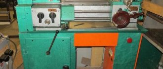
Appearance of machine 1512