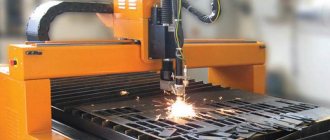
Plasma cutting is a technological operation for separating materials, in which a plasma jet plays the role of a cutting tool. The essence of the plasma cutting process is the high-speed passage of a stream of ionized gas, i.e., plasma, through a tapering hole (nozzle), which acts as a conductor of electric current between the torch (plasma torch) and the material being cut. It heats and melts the products. A high-speed plasma stream then mechanically blows away the melt, separating it.
The temperature of the plasma flow varies from 5000 °C to 30000 °C, speed - from 500 m/s to 1500 m/s.
The main purpose of the operation is cutting metal elements with a thickness of up to 25 mm. The maximum material thickness for plasma cutting does not exceed 200 mm. The thickness of the metal cut by plasma depends on its thermal conductivity. Namely: the greater the thermal conductivity of the metal, the thinner the product that can be cut. To obtain a plasma jet use:
- inactive gases (nitrogen, hydrogen, water steam) - plasma cutting of non-ferrous metals;
- active gases (oxygen, air) for cutting ferrous metals.
Advantages and disadvantages of the plasma cutting method
Let us note the main advantages of this technological operation:
- Plasma cutting is used for both ferrous (steel, cast iron) and non-ferrous (aluminum, copper) metals. Non-metallic materials (concrete) can also be cut;
- high speed, productivity, accuracy;
- the ability to cut out shapes of complex configurations;
- excellent edge surface quality. The edge does not need to be subjected to additional machining;
- safety, environmental friendliness of the technological process. It does not use flammable gas or compressed oxygen, and there are practically no harmful emissions;
- versatility of the operation: the ability to cut large-width parts, pipe blanks, and perform cuts at a certain angle;
- The workpiece does not need to be preheated before use. This significantly saves the time of the technological operation.
But in the modern, innovative plasma cutting process there are also negative aspects:
- when cutting thick workpieces, it is necessary to use high-power sources of electricity;
- the need to attract trained qualified personnel for work;
- limitation on the thickness of processed parts;
- Plasma cutting work is accompanied by a high noise level;
- high price of equipment.
Cutting pipes under route conditions
- TPA Directory
- GOST 9702-87 Cone and ball valves. Main settings
- Cutting pipes under route conditions Cutting pipes under route conditions
Cutting pipes under route conditions Cutting pipes under route conditions 4.1. Acetylene or its substitutes can be used as a flammable gas for oxy-fuel cutting: propane, propane-butane mixtures, natural gas, as well as kerosene or gasoline. 4.2. Qualified cutters who know the structure, rules of maintenance and repair of equipment are allowed to work with equipment for manual machine oxygen and plasma cutting and repair it. Regardless of the presence of a certificate, the carver must pass an exam according to the technical minimum of the qualification commission of the installation department. 4.3. Machine oxygen cutting 4.3.1. Mechanized cutting should be performed using Orbita-2 or Sputnik-3 gas cutting machines. 4.3.2. Before cutting, snow and dirt should be removed from the pipe over a section of at least 0.5-1.0 m in length, since the presence of moisture impairs the quality of the cut and the structure of the metal edge. 4.3.3. The cut section of the pipe, 50-100 mm wide around the perimeter, must be thoroughly cleaned with a mechanical or manual wire brush. The surface of the pipe should be free of a layer of primer, traces of insulation, scale, rust, dust, oil and grease contamination. Cutting uncleaned metal leads to a significant decrease in process productivity and deterioration in the quality of the cut surface. 4.3.4. The cutting speed and oxygen pressure must correspond to Table 43. Table 43
| Metal thickness, mm | Machine cutting modes for application | |||||
| acetylene | propane | |||||
| Cutting speed, mm/min | Oxygen pressure, MPa | Combustible gas pressure, MPa | Cutting speed, mm/min | Oxygen pressure, MPa | Fuel gas consumption, l/m | |
| 5-10 | 600-400 | 0,35-0,4 | 0,04-0,045 | 500-400 | 0,4-0,45 | 25-35 |
| 10-20 | 500-400 | 0,4 -0,5 | 0,04-0,045 | 400-300 | 0,45-0,55 | 35-45 |
| 20-30 | 400-350 | 0,5-0,7 | 0,045-0,05 | 300-350 | 0,55-0,75 | 45-55 |
4.3.5. Cutting begins by burning a hole in the body of the pipe as follows: the cutter is brought to the place where the hole is punched, the combustible mixture of the cutter is ignited, the punched area is heated to the ignition temperature in a stream of oxygen, and the supply of cutting oxygen is constantly turned on. 4.3.6. After punching the holes, the drive is turned on to move the cutter around the perimeter of the pipe. 4.3.7. Pipe cutting is carried out along the closed perimeter of the pipe, starting from the bottom position. 4.3.8. During the cutting process, it is necessary to ensure compliance with the selected mode, i.e. keep the composition of the mixture, the distance between the cutter mouthpiece and the metal, cutting speed, and gas pressure unchanged. 4.3.9. The roughness of the cut edge should not exceed 0.16 and 0.32 mm when the thickness of the metal being cut is 5-15 and 16-30 mm, respectively, which corresponds to class 3 according to GOST 14792-80. 4.3.10. Before welding after machine oxy-fuel cutting, it is necessary to carefully remove burr and scale from the cut edge. 4.3.11. On edges after machine gas-oxygen cutting, it is allowed to perform manual arc welding with electrodes with the main type of coating, automatic submerged arc welding using manual welding and double-sided welding. 4.3.12. Welding with cellulose-type coated electrodes is allowed only after mechanical processing of the cut edges or cleaning them with grinders. 4.3.13. Cutting pipes at subzero ambient temperatures may be accompanied by the appearance of cracks in the cutting edge. 4.3.14. To avoid the formation of cracks and obtain more ductile metal at the cutting line, depending on the composition of the steel, the thickness of the metal, and the cutting mode, it is necessary to use preheating. 4.3.15. The need for heating and the choice of heating temperature for machine oxygen cutting are determined in accordance with Table 44, depending on the carbon equivalent of steel and the type of gas used (acetylene, propane).
Table 44
| Carbon equivalent, % | Acetylene | Propane | ||||||
| Pipe wall thickness, mm | ||||||||
| 10 | 15 | 20 | 25 | 10 | 15 | 20 | 25 | |
| 0,3-0,4 | A | A | A | A | A | A | A | A |
| 0,41-0,50 | A | A | B (-30°C) | B (0°C) | A | A | A | B (-40°C) |
| 0,51-0,56 | A | B (-30°C) | B (0°C) | B (+20°С) | A | A | B (-30°C) | B (0°C) |
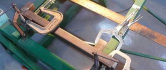
Notes: A - cutting without heating at air temperatures down to -50 C; B - heating to +50°C is necessary when the air temperature is below the temperature indicated in brackets; B - heating to +100°C at a temperature below the temperature indicated in brackets. 4.3.16. When new pipes made from high-strength steels with a wall thickness of more than 25 mm arrive, it is recommended to check the pipe metal for hardenability using machine oxygen cutting by bending samples according to the scheme shown in Fig. 21.
Fig.21.
Scheme of sample loading during bending angle testing 4.3.17. The sample dimensions are taken in accordance with GOST 6996-66: diameter of the loading mandrel, sample thickness (but not more than 16 mm); — pipe wall thickness, mm. 4.3.18. The bend angle must be at least 30°. Developing cracks visible to the naked eye are not allowed to appear on the cut surface. 4.3.19. If, when bending samples up to 30°, cracks appear on the cut edge, you should adjust the cutting modes by applying preheating (or increasing the heating temperature), or increase the power of the preheating flame of the cutter. 4.3.20. Preheating should be performed with stationary ring heaters used to heat pipe joints before welding. 4.3.21. Disposing of pipes or coils to be welded into snow or water until they have completely cooled after completion of the cutting process is not permitted. 4.3.22. Straightening of pipe ends after oxygen cutting of metal with a standard tensile strength value of up to 540 MPa at positive air temperatures can be performed without heating; at negative ambient temperatures, heating to 150-200°C is necessary before straightening. 4.3.23. At negative air temperatures, the evaporation of flammable gases, as a rule, stops. In this case, the cylinder should be placed in a container with continuously heated hot water. 4.3.24. When the hoses and gearbox freeze, they should be warmed up with hot water, followed by blowing with air and wiping from the outside. Water and air should be free of fats and oils. 4.4. Manual oxygen cutting 4.4.1. Manual oxygen cutting of pipes should be performed with cutters “Mayak-1-02”, “Mayak-2-02”, RUA-70, “Fakel”, RUZ-70, RK-71, RZR-62, “Plamya”. Cutters “Mayak-2-02”, “Plamya”, “Fakel” and RUA-70 are designed for oxygen-acetylene cutting; cutters "Mayak-2-02", RUZ-70 and RZR-62 - for oxygen cutting using acetylene substitute gases, cutter RK-71 - for cutting with kerosene. The hand cutter is supplied with internal and external mouthpieces, replacement mouthpieces, a key, and O-rings. 4.4.2. Before use, new cutters must be checked in a gas-cutting equipment repair shop (and where there is none, by mechanics authorized to repair gas-cutting equipment) for suction, leaks and combustion. Each cutter is subject to inspection, since the manufacturer carries out a random inspection of the batch, and does not check all the cutters produced. 4.4.3. Before starting work, it is necessary to check the correct connection of the hoses to the cutter (the oxygen hose is connected to a fitting with a right-hand thread, the combustible gas hose is connected to a fitting with a left-hand thread), injection in the combustible gas channels, and the tightness of all detachable connections. 4.4.4. Gas leaks in threaded connections are eliminated by tightening them. 4.4.5. The operating pressures of oxygen and acetylene are set in accordance with the cutting mode given in Table 45.
Table 45
| Pipe thickness, mm | Mouthpiece number | Cutting speed, mm/min | Pressure oxygen, MPa | Acetylene pressure, MPa | |
| outdoor | internal | ||||
| 8-10 | 1 | 1 | 400-350 | 0,3 | Not less than 0.01 |
| 10-25 | 1 | 2 | 350-250 | 0,4 | Not less than 0.01 |
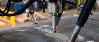
4.4.6. If the tip becomes very hot, it should be cooled with clean water. To prevent water from getting into the cutter channels, close only the flammable gas valve, leaving the oxygen valve open. 4.4.7. If the mouthpiece channels become clogged, they must be cleaned with a copper or aluminum needle. 4.4.8. All minor malfunctions: misalignment of mouthpieces, leaky connections, clogging of injectors and mouthpiece channels, carbon deposits and splashes on the surface of the mouthpiece, lack of suction in the combustible gas channel, frequent flame pops, faulty valves are eliminated by the cutter. 4.4.9. Manual oxygen cutting of pipes made of low-carbon and low-alloy steels, including at negative ambient temperatures, can be performed without any technological restrictions. The main requirement is to obtain an even cut and the required cutting parameters. 4.4.10. Straightening of pipe ends after oxygen cutting of metal with a standard tensile strength value of up to 540 MPa at positive air temperatures can be performed without heating; at negative ambient temperatures, heating to 150-200°C is necessary before straightening. 4.5. Air plasma cutting 4.5.1. The Orbita PL-1 installation is intended for mechanized air-plasma cutting of pipes during the construction of main pipelines. 4.5.2. To perform cutting, the container with the installation must be located at a distance of at least 1.5-2 m from the pipe being cut. 4.5.3. A guide belt corresponding to its diameter is mounted on the pipe being processed. To ensure cutting accuracy, it is necessary to carefully align the installation of the guide belt. The chassis of the Orbita machine is mounted on a guide belt. 4.5.4. The surface of the pipe in the place where the cut begins and where the main arc should be excited is cleaned of scale, dirt, oil, rust, paint, and the pipe cavity is cleared of dirt, snow, etc. When cutting insulated pipes, the place where the cut begins must be cleared of insulation , then clean the surface of the pipe in this place to a metallic shine. 4.5.5. Before starting work, you need to check the power source: the condition of the electrical wires and contacts; compliance of the mains voltage with the voltage indicated on the power supply label; connecting the power source to the compressor. 4.5.6. The plasma torch is connected to the power source; for this it is necessary to connect in order: air supply; pilot arc high voltage wire plug; inserting the control wire plug connector into the block. 4.5.7. One end of the “+” cable is connected to the “+” terminal of the power source, and the other to the pipe being processed. 4.5.8. The plasma torch is fixed in the support holder of the chassis of the Orbita machine. 4.5.8.1. The distance between the plasma torch and the surface of the pipe being cut should be 10-15 mm, and its position should not change during the cutting process. 4.5.8.2. The angle of inclination of the plasma torch to the generatrix of the pipe must correspond to the required bevel angle of the edges. 4.5.9. The electrical cable for driving the chassis of the Orbita machine is connected to the power supply through an adapter box. 4.5.10. To ensure operational safety, check the double or reinforced insulation of the cable connecting the “-” sign of the rectifier to the plasma torch, double insulation of the connection point of this cable to the rectifier and to the plasma torch; The rectifier housing must be isolated from all parts of the installation. 4.5.11. The rectifier is connected to the 3x380+0 alternating current network through circuit breakers. 4.5.12. At subzero air temperatures, before starting work, the chassis of the Orbita machine is turned on to operate at high speeds without idle for 2-3 minutes in order to warm up the lubricant in the mechanical gearbox. 4.5.13. Hoses and cables leading from the power source to the plasma torch are positioned in such a way that while the machine is moving around the pipe, they do not interfere with the operation of the plasma torch. 4.5.14. To supply voltage to all installation devices, the circuit breaker handle is set to the “on” position. 4.5.15. The compressors are turned on, and at the UPR-201 power source, using a pressure regulator, the air pressure is set to 0.4 MPa. 4.5.16. On the power source, according to the indicator using a resistor for regulating the operating current, set the required current strength in accordance with the air plasma cutting modes given in Table 46.
Table 46
| Metal thickness, mm | Current strength, A | Voltage, V | Cutting speed, m/min |
| 9-15 | 150-170 | 115-120 | 1,2-0,8 |
| 16-25 | 170-200 | 110-115 | 1,0-0,6 |
4.5.17. Before proceeding directly to cutting, it is necessary to check the ignition of the pilot arc. To do this, raise the plasma torch in the holder to a distance of 150-200 mm from the surface of the pipe being cut, press the “start” button on the remote control; at the same time, a visible intermittent pilot arc torch should appear from the nozzle. The auxiliary arc may not be excited for the following reasons: the power source is faulty, the air pressure is higher than permissible, the insulation of the plastic sleeve in the plasma torch is broken, the plasma torch is assembled incorrectly. 4.5.18. If the auxiliary arc is excited, it is turned off by pressing the “stop” button, and the plasma torch is installed above the starting point of cutting at a height of 10-15 mm from the surface of the pipe. 4.5.19. The toggle switch on the remote control switches on the movement of the Orbita machine in the selected direction (the direction of movement should be such that the plasma flow blows off the molten metal from the edge intended for welding). 4.5.20. Press the “start” button on the remote control. In this case, an auxiliary arc is ignited between the electrode and the plasma torch nozzle using an oscillator, which is blown out of the nozzle in the form of a plasma torch 10-15 mm long. When the pilot arc torch touches the pipe metal, a cutting arc occurs between the plasmatron electrode and the pipe metal. The pilot arc is automatically switched off. 4.5.21. In order to finally adjust the speed of the Orbit machine, rotate the speed regulator on the remote control; in this case, the deviation of the arc torch from the cutter axis should be 20-30°. 4.5.22. When air plasma cutting, the following must be observed: the established cutting mode (pay attention to the correct shape and constant deflection of the arc torch); arc stability; continuity of the cutting process; constant operating air pressure according to the pressure gauge; constant distance between the cutter and the surface of the pipe being cut (within 10-15 mm). 4.5.23. After finishing cutting, break the arc by pressing the “stop” button. 4.5.24. If the film cathode wears out as a result of evaporation of the insert material to a depth of more than 3.5 mm, it should be replaced. 4.5.25. After the edge has cooled, slag and burr are removed from the cut surface with a wire brush and chisel. The cut surface is subjected to external inspection to check the quality of the cut surface. 4.5.25.1. The misalignment of the beginning and end of the annular cut should not exceed 2 mm (Fig. 22).
When welding overlaps (to reduce the cutting error when cutting the end of the second pipe), the plasma torch is installed at a point diametrically opposite to the beginning of the cut of the first pipe. Fig.22.
Misalignment of the beginning and end of the cut 4.5.25.2. Surface roughness is measured by the actual height of micro-irregularities on the cut surface.
It is determined at a base length of at least 8 mm at 10 points in the middle of the thickness of the pipe being cut. The roughness should not exceed 1.0 mm with a pipe metal thickness of 5-12 mm and 1.2 mm with a thickness of 13-30 mm (GOST 14792-80) (Fig. 23). Fig.23.
Roughness of the cut surface 4.5.25.3. The cut angle (deviation from perpendicularity with respect to the longitudinal axis of the pipe) should not exceed 2 mm. 4.5.26. If the quality of the cut surface does not meet the requirements of clause 4.5.25, it should be corrected by grinding the roughness and steps on the surface to the specified values. 4.5.27. To avoid the formation of pores during welding (possible saturation of the cut surface with nitrogen), the cut surface must be cleaned with an abrasive wheel (grinding machine) to a metallic shine (to a depth of 0.3-0.5 mm) with the formation of a bluntness in the lower part of 1.5-2 mm. 4.5.28. When the wind speed is more than 5 m/s and there is precipitation, cutting without covering the workplace is not recommended. 4.6. Manual and machine air-arc cutting (sampling of defects in seams and base metal) 4.6.1. Qualified cutters or welders who know the design and maintenance rules of the equipment are allowed to use air-arc cutting. Regardless of the presence of a certificate, the cutter (welder) must pass an examination at the technical minimum of the qualification commission of the installation department. 4.6.2. Mechanized air-arc surface cutting is performed on an air-arc cutting installation. 4.6.3. Manual air-arc cutting is performed using a cutter RVDm - 315. 4.6.4. For air-arc cutting, carbon or graphite electrodes with a round cross-section with a diameter of 6-12 mm should be used. Recommended current density at the electrode is 4-6 A/mm. 4.6.5. Before starting work, the electrodes must be calcined in an oven at a temperature of 150-200°C for 3-4 hours to prevent their possible explosive destruction during operation due to moisture accumulated in the pores. 4.6.6. The air-arc cutting installation is prepared for work in the following order: a guide belt corresponding to its diameter is mounted on the pipe being processed; the transport device with a feeding mechanism with an electrode holder installed on it is fixed on the guide belt; current-carrying communications from the power source and gas-carrying communications from the compressor are connected to the air-arc cutting installation; A carbon electrode is inserted into the electrode holder of the installation. The distance between the electrode and the workpiece must be at least 5 mm; using a pressure gauge, set the working pressure of compressed air (0.4-0.6 MPa); on the remote control panel, set the required cutting speed and electrode feed speed; connect the power source to the network; set the required current and voltage parameters. 4.6.7. Preparation for manual air-arc cutting is carried out in the following order: connect the current-carrying communications of the RVDm-315 cutter to the power source, and the gas-carrying communications to the compressor; the carbon electrode is inserted into the cutter so that the electrode extension is 100-120 mm; using a pressure gauge, set the working pressure of compressed air (0.4-0.6 MPa); connects the power source to the network. 4.6.8. The process of machine and manual cutting should be performed with direct current of reverse polarity (plus on the electrode). 4.6.9. The diameter of the carbon electrode should be selected depending on the depth of the melted groove (depth of the defect) in the welded joint (Table 47). 4.6.10. Surface air-arc cutting, depending on the depth of the defects, should be performed in the modes given in Table 47.
Table 47
| Cut dimensions, mm | Electrode diameter, mm | Current strength, A | Voltage, V | ||
| depth | width | groove radius | |||
| 10,0-12,0 | 12,0-14,0 | 5,0 | 10-12 | 480-500 | 45-50 |
| 8,0 | 11,0 | 4,0 | 8 | 400-420 | 55-60 |
| 7,0 | 10,0 | 3,5 | 6 | 300-330 | 55-60 |
Note. Cutting speed 30-35 m/h; electrode tilt angle 40-45°; air pressure 0.4-0.6 MPa. 4.6.11. The cutting direction should be forward, otherwise the molten metal will not be blown out. The smaller the angle between the electrode and the metal being processed, the shallower the groove depth and the higher the cutting speed should be. 4.6.12. When cutting manually, it is recommended to ignite the arc at the lead plate. When lighting an arc on a seam, it is recommended to quickly move the arc back 5-10 mm and only start cutting from this place. In this case, the arc ignition zone will be completely removed during the cutting process. 4.6.13. Due to the inertia of establishing the required penetration depth, the beginning of the cut must be at a distance of at least 50 mm from the location of the defect. 4.6.14. In the process of manual air-arc cutting, due to burning of the electrode, its extension decreases, therefore it is necessary to periodically move the electrode in the holder, restoring the electrode extension to 100-120 mm. 4.6.15. The uniform movement of the electrode during cutting should be observed, since fluctuations in the movement speed lead to changes in the depth and width of the groove along its length. 4.6.16. It is necessary to maintain a constant electrode feed speed, since the constancy of the arc length, the stability of its combustion and the quality of the cut depend on this. At a low electrode feed speed, the arc length increases and the stability of the cutting process is disrupted. Increasing the electrode feed speed during surface air-arc cutting leads to the fact that the frontal edge of the cut does not have time to melt and the electrode seems to cut into the metal. The arc goes out and the cutting process is interrupted. 4.6.17. It is necessary to avoid short circuits of the electrode to the metal being processed, since this process is accompanied by carburization of the surface being processed. 4.6.18. If the electrode is partially or completely destroyed during the cutting process, stop the process and thoroughly clean the working surface, removing electrode particles. 4.6.19. The cut surface should be cleaned from burrs with abrasive wheels using a grinding machine to a metallic shine (to a depth of 0.3-0.5 mm) after removing defects from the welded joint by air-arc cutting. In this way, defects can be avoided during subsequent welding of the groove.
Pipe fittings portal Armtorg.ru
Barnaul, Zavodskoy 9th passage, 5g/8.
+7 (3852) 567-734; +7 (3852) 226-927
Share
Previous article Next article
← back to section GOST 9702-87 Cone and ball valves. Basic parameters ← return to directory table of contents
Latest registered companies (Register
Russia, St. Petersburg
IP Peregudov Artem Vladimirovich
Russia, Novosibirsk region
KrasEliteStroy
Russia, Krasnoyarsk region Cloud of goods
.Other...2068 Safety valve blocks146 Bronze valves137 Steel valves949 Cast iron valves570 Energy valves144 Stainless steel valves370 Steel valves2163 Steel valves - HL371 Cast iron valves1102 Energy valves86 Steel valves294 Cast iron valves33 5 Test equipment for injection molding machines119 Check valves974 Shut-off valves61 Safety valves1120 Control valves560 Energy valves128 Bellows compensators203 Steel condensate drains55 Cast iron condensate drains67 Boiler equipment220 Bronze taps149 Stainless steel taps179 Steel taps608 Steel taps - HL87 Cast iron taps149 Pressure gauges88 Hardware433 Pumps246 Bends1081 Heating equipment96 Switching devices46 Transitions461 Fire fittings48 Radiators33 Control fittings34 1 Repair equipment for injection molding machines53 Water meters159 Thermometers47 Tees492 Pipes702 Level indicators71 Sealing materials67 Filters, strainers410 Fittings206 Flanges2400 Ball valves1244 Electric drives251
Equipment for plasma cutting of metal
To carry out cutting using plasma, it is necessary to obtain the plasma arc itself. For this purpose, a special apparatus is used - a plasmatron, which consists of:
- nozzle - plasma outlet;
- an electrode made of a metal with a high melting point (tungsten, zirconium);
- channel for supplying compressed gas (air, purified oxygen);
- an insulating element that simultaneously plays the role of a cooler.
Some of the structural elements of the plasma torch, which operate in areas of high temperatures and significant dynamic loads, may wear out and require periodic replacement. Such elements include:
— electrodes;
— plasmatron nozzle;
— insulating units;
— a diffuser where the swirling of the working gas flow occurs.
In addition, various protective screens and casings are considered consumable items, which make working with the plasma torch more comfortable.
Wear of consumable parts can lead to deterioration in cut quality and breakdown of expensive equipment. Therefore, it is necessary to promptly identify wear of consumables and replace them.
The installation for plasma cutting includes:
- transformer or inverter, current converter to create an electric arc;
- compressor for supplying gas under pressure;
- plasmatron for generating flow;
- air supply tube connected to an electrical cable.
Although the most important technological process occurs in the plasma torch, plasma cutting is impossible in the absence of any other piece of equipment.
Video description
Gorynych - plasma welding and cutting machine
So, the gas in the plasma torch is heated by the plasma arc, which leads to its ionization. The volume of hot gas due to the property of thermal expansion increases from 50 to 100 times, which contributes to high-speed ejection from the nozzle. It turns out that kinetic and thermal energy are the main reasons for the appearance of a powerful energy flow in plasma welding. It should also be noted that the plasma torch usually uses DC torches.
There are several types of such units:
- the arc is between the consumable electrode and the weld pool;
- the arc is between the non-consumable electrode and the weld pool, and the plasma is ejected as a gas stream.
Note: Gases used to form plasma are argon (Ar), nitrogen (N2), oxygen (O2) or ordinary air.
Also, all welding of this type differs in current strength:
- small (microplasma) – 0.1-50 A;
- medium - 50-150 A;
- large from 150 A and above.
If the microplasma option allows you to avoid burn-throughs in the parts being welded, then units operating at high currents melt metal up to 8 mm thick in one pass without edge cutting, which makes it possible to cut workpieces without much difficulty. It is quite natural that at medium currents you will be able to both weld and cut metal.
Plasma torch operation process
After pressing the button, an electric current flows into the device and the primary electric arc with a temperature of about 8000 °C lights up inside and spreads over the entire area of the channel.
The compressor begins to supply compressed air into the channel with the primary arc, which, passing through the channel, heats up and acquires the properties of an ionized gas that conducts electric current. Due to high heating temperatures, air expands in volume by 50-100 times. This significantly increases gas pressure.
Then, through the channel, the hot, expanded gas flow enters the nozzle, which narrows it and makes it more concentrated. The air flow, converted into plasma, flies out of the nozzle opening at enormous speed (about 3 km/s). In this case, the temperature of the ionized flow increases several times.
It is this ionized gas, heated to enormous temperatures, that is the plasma through which cutting is carried out.
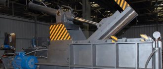
Numerically controlled machine
Machine for plasma cutting of pipes with CNC
The machines allow plasma cutting of pipes with high precision with minimal defects due to the presence of CNC. The machine itself is controlled by a controller or a separate computer. The control program is created based on a three-dimensional model of the cut shape. If you have a sample, it can be scanned with a special scanner, which will create a 3D image in electronic form.
Important! By varying the diameter of the plasmatrons, the speed of passage and the angle of inclination, you can obtain a high-quality cut of any complexity.
The main components that the CNC pipe cutter is equipped with:
- plasmatron;
- controller;
- cutting table;
- support for moving the cutter;
- units for supplying gas, electricity and water.
Types of plasma cutting
Separation using plasma is classified according to a number of characteristics.
By cutting method:
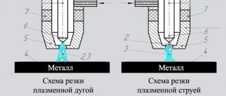
- arc. In this case, the material being cut acts as part of an electrical circuit;
- jet. The material is not part of the chain. An electric arc is formed between the electrodes.
Based on the depth of cut, there are:
- superficial, in which the product is not divided into parts;
- separation, in which the metal is divided into several separate parts.
Separation plasma cutting is used more often.
According to the properties of the environment in which the technological process occurs:
- the usual type of cutting using ambient air.
- cutting using protective gas.
- cut using water.
In the latter case, water protects the cut from environmental influences, cools the cutter (plasma torch), and absorbs harmful fumes.
Advantages
Plasma cutters for metal are often used on construction sites and in private workshops. The demand is explained by the advantages of the plasma cutter:
- Using a plasmatron you can process different types of metals and alloys.
- There is no need to prepare the work surface. High quality processing can be achieved without cleaning the metal from rust and paint.
- By carefully and slowly moving the cutter along the surface being processed, a highly accurate cut is obtained. No scale or sagging remains.
- Even if the metal sheet is not very thick, it will not be damaged due to strong heating. This is due to the characteristics of the equipment used.
- Using a plasma cutter you can make smooth, shaped cuts.
During operation of the plasma torch, virtually no harmful substances are released, which makes the processing process safe for health.
Plasma cutting of metals is a technological process using a special tool that allows you to cut metal sheets. The choice of plasma torch depends on what materials will be processed. If the device is not selected correctly, the plasma arc will not be able to cut the metal workpiece.
Types of cutting systems
Systems differ depending on the type of plasma gas provided by the technology.
Conventional systems use ambient air as gas. The current strength in this process ranges from 12-20 thousand A/in². The shape of the plasma flow depends on the nozzle opening. Such systems are used for both manual and mechanized cutting. Deviations in the dimensions of the cut part are allowed.
High frequency (high current density) systems are used for plasma cutting with increased precision. Purified air, oxygen, and mixtures of hydrogen and nitrogen are used as plasma gas. Plasmatrons and consumables of a more complex design are used in the technological process. The current strength for high-frequency separation is 40-50 thousand A/in². The main goal is to achieve increased accuracy when focusing the arc and obtain high quality cutting.
The most popular plasma welding machines in Russia
This is a generator of electric arc low-temperature plasma, obtained by heating the vapors of the working fluid to an ionization state and is intended for metals Source sevproekt.rf
MPK (multifunctional portable plasma complex) Gorynych is designed to generate plasmas from a liquid - water or a water-alcohol mixture, where the steam performs a protective function . Such units are produced with a current of 8,10 and 12 A and at the same time they are universal, that is, Gorynych can both cut and weld various parts, but that’s not all. By setting the required power, the device can be used as a blowtorch, a forge, and even a fire extinguisher if water is used as the liquid. The MPPC is quite light - the weight of the plasma torch with cable and hose does not exceed 5.4 kg, and to power it you need a regular socket ≈220±22 V and 50 A. The unit creates a straight polarity arc with an efficiency of at least 80%.
Being a new generation device, with improved quality, it is more than 2.5 times more economical and 5 times lighter than the plasmatrons used Source eduard-romanov.uaprom.net
If we talk about money, Multiplaz-15000 is the most profitable plasma welding machine among its analogues. In addition, such a unit can be called the lightest among similar ones, for example, the weight of the power source is 33 kg and the weight of the plasma torch together with a cable and a 9-meter hose is 5 kg. Power consumption is 15 kW at an input voltage of 380±38 V, with a network frequency of 50 A. Welding operates in the current range from 20 to 100 A, consumes 480 l/min of compressed air and its efficiency is 85% - this allows you to cut thick steel sheets up to 50 mm. Of course, Multiplaz-15000 is more suitable for industrial enterprises and auto repair shops, but it is also bought for domestic use.
Robot
Robotic plasma cutting
*
Thanks to software developments, robotic cutting is becoming increasingly used. Robots are widely used in automotive, mechanical engineering and other fields. Previously, it took weeks, or even months, to reconfigure equipment. Now it takes minutes. Therefore, the scope of robots has expanded from mass production of similar parts to the execution of individual orders.
In addition, automated systems provide continuous monitoring of the specified parameters of the technological process, which sharply reduces the percentage of defects.
Modern robots allow cutting at any angle, anywhere, using a robotic arm that can move precisely in any direction. The long arm allows you to cut large diameter pipes.
As additional equipment, robotic complexes can be equipped with sensor systems and technical vision systems that allow continuous monitoring of the process.
Thanks to the technical vision system, it is almost impossible not to “not notice” a defective product. It also becomes possible to identify deviations and then adjust the parameters during the technological cycle.
Thanks to these factors, robotic cutting is carried out at a level inaccessible to manual labor. Application is limited by high cost.