We consider simple circuits of digital voltmeter and ammeter, built without the use of microcontrollers on the CA3162, KR514ID2 microcircuits. Typically, a good laboratory power supply has built-in instruments - a voltmeter and an ammeter. A voltmeter allows you to accurately set the output voltage, and an ammeter will show the current through the load.
Old laboratory power supplies had dial indicators, but now they should be digital. Nowadays, radio amateurs most often make such devices based on a microcontroller or ADC chips like KR572PV2, KR572PV5.
Ammeter for homemade power supply
In order to make a shunt, it is necessary to calculate its resistance. Go to the “Site Map” page, select the “Programs” category, go to the “Programs” note and download the “Program for working with wire”. Yes, there is a program. Now we take the measuring head, it is better if it has a current of full deflection of the needle of 50 or 100 microamps. These parameters are called the sensitivity of the measuring head. Let's make a calculation for a head with a current of 50 microamps. Let's set the measured current, let's say 10A.
1) We measure the resistance of the device (head), for mine it is 1454 Ohms. 2) We substitute all available data into formula 1: Device current - Idevice = 0.00005A; The measured current is Imeasured = 10A. Device resistance Rdevice = 1454 Ohms. 3) The shunt resistance was determined Rsh=0.00727 Ohm.
Open the program. Press the second button at the top to determine the length of the shunt. On the right, from the drop-down list, select the material for the shunt. For such ammeters, I always use light tinned tin from condensed milk cans as a material. And so, we choose steel.
Its resistivity is approximately 10 times greater than that of copper, so the geometric dimensions of the shunt will be smaller. We measure the thickness of the tin with a micrometer; mine is 0.2 mm. We choose the width of the strip of tin, nine millimeters for a current of ten amperes, I think, is enough, especially since the flat conductor has a large cooling area.
Charger assembly
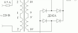
Connect a cord with a power plug and a fuse to the primary winding of the TS-180-2 transformer, install the diode bridge on the radiator, connect the diode bridge and the secondary winding of the transformer. Solder the capacitor to the positive and negative terminals of the diode bridge.
Connect the transformer to a 220 volt network and measure the voltages with a multimeter. I got the following results:
- The alternating voltage at the terminals of the secondary winding is 14.3 volts (mains voltage 228 volts).
- The constant voltage after the diode bridge and capacitor is 18.4 volts (no load).
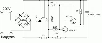
Using the diagram as a guide, connect a step-down converter and a voltammeter to the DC-DC diode bridge.
Multimeter device
A modern multimeter (tester) is a complex electronic device. These measuring instruments differ in their operating principle and the way they display the results obtained. Moreover, their design and appearance depend entirely on the manufacturer, who has the ability to equip multimeters with additional capabilities. For example, there are testers equipped with built-in conductive clamps that allow you to measure the electrical parameters of circuits without breaking the wires.
Classification and principle of operation
By design, multimeters can be stationary and small-sized. In addition, based on the circuit design, they can be:
Stationary multimeters usually operate from a centralized power supply network. They are high-precision electronic devices and are used for precision measurements in laboratory or industrial settings. They also work as part of information-measuring systems and specialized industrial complexes. Small-sized (pocket) testers use built-in batteries or replaceable power supplies to measure resistance.
In analog multimeters, the measurement result is displayed by the deflection of the needle on a graduated scale, and in digital multimeters - on an LED display or liquid crystal screen. There may also be original models equipped with both a dial indicator and a digital screen.
The electrical circuit of analog-type dial multimeters is simple and consists of a set of shunt precision resistors of large and small values. In order to use such testers to measure the parameters of AC electrical circuits, rectifier diodes are introduced into the circuit. This is due to the fact that the magnetoelectric system of a pointer microammeter operates only on direct current.
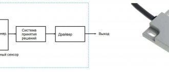
Electrical circuits of digital multimeters are much more complex and contain the following components:
- operational amplifier;
- attenuator;
- analog-to-digital converter;
- high-precision rectifier;
- mechanical or electronic switch.
The block diagram is basic for all digital multimeters and allows you to measure the parameters of DC and AC electrical circuits with high accuracy.
The operating principle of analog testers is based on the fact that the measurement is preceded by the conversion of all incoming signals into current, which is then measured. In contrast, digital multimeters pre-convert all incoming signals into voltage.
Join the conversation
Given the wide range of modern voltammeters, you may encounter problems connecting them. We connect the resistor to the voltmeter-ammeter Second. But let's look at the colors of the wires.
Not everyone will immediately understand which wire needs to be connected where, and the instructions are usually only in Chinese.
Most devices can be adjusted using built-in resistors. The fan speed will also decrease, but at low voltage the power supply heatsinks will be a little warm and nothing bad will happen.
Diagram for connecting a voltmeter-ampmeter to an adjustable power supply. At the bottom of the circuit, the fan and the Chinese voltmeter-ampmeter are connected through an LCV voltage stabilizer to the output of the diode bridge in parallel with capacitor C1.
It was not immediately and at the right time that it became clear that its power input was galvanically connected to the minus input of the shunt. Chinese voltmeter - ammeter after modification Here it turned out that the wirewound resistor, instead of the recommended resistance of 0.08 Ohm, has 0.8 Ohm.
It is more expensive than previous models, but also has a higher upper limit of measurements in V. It was possible, of course, to install another duty station and power the indicator from it, but it seemed to me too bold and I decided to hack the indicator itself. How to connect a Chinese ammeter voltmeter
Shunt for an ammeter - how to make it yourself, calibrate and expand the capabilities of the tester
Measuring current is a fairly important procedure for calculating and testing electrical circuits. If you are creating a device with power consumption at the level of charging a mobile phone, a regular multimeter is enough to measure.
A typical inexpensive household tester has a current measurement limit of 10 A.
Most of these devices have an additional connector for measuring larger quantities. When rearranging the measuring cable, you probably haven’t thought about why you need to organize an additional circuit, and why you can’t just use the mode switch?
↑ Files
Schematic, printed circuit board and program with firmware